Instrument panel electrical diagram Kalina 2
1,2 – blocks of the instrument panel wiring harness to the blocks of the front wiring harness; 3, 4 – blocks of the instrument panel wiring harness to the blocks of the rear wiring harness; 5 – lighting control module; 6 – ignition switch; 7 – on-board computer mode switch; 8 – windshield wiper switch; 9 – instrument cluster; 10 – light signaling switch; 11 – trunk lock drive switch; 12 – diagnostic block; 13 – block of the instrument panel wiring harness to the block of the wiring harness of the air supply box; 14 – rear window heating switch; 15 – alarm switch; 16 – brake signal switch; 17 – multimedia system; 19 – rotating device; 20 – driver airbag module; 21 – sound signal switch; 22 – mounting block: K1 – relay for the electric fan of the engine cooling system; K2 – door lock relay; K3 – additional starter relay; K4 – additional relay; K6 – windshield wiper relay; K7 – headlight high beam relay; K8 – sound signal relay; K9 – relay for low beam headlights; K10 – relay for turning on the heated rear window; K11 – main relay; K12 – fuel pump relay; 23 – electric power steering; 24 – cigarette lighter; 25 – lampshade lighting of the glove box; 26 – glove box lighting switch; 27 – block of the instrument panel wiring harness to the block of the ignition system wiring harness; 28 – engine control system controller; 29 – block of the instrument panel wiring harness to the block of the rear wiring harness 4; 30 – electronic accelerator pedal; 31 – heater motor speed regulator; 32 – heater electric motor; 33 – solar radiation sensor; 34 – ESC switch; 35 – relay (K13) of the electric fan of the engine cooling system 3; 36 – compressor relay (K16); 37 – relay (K14) for heating the windshield; 38 – relay (K15) for heating the windshield 2; 39 – headlight range control regulator; 40 – additional relay; 41 – passenger airbag module; 42 – evaporator temperature sensor; 43 – steering angle sensor; 44 – windshield heating element; 46 – windshield heating switch; 47 – central unit of body electronics; 48 – micromotor reducer of the air flow distributor flap; 49 – gear shift control drive; 50 – controller of the automatic climate control system; 51 – micromotor gearbox for mixing air flows; 52 – micromotor gearbox for recirculation damper drive.
How to open the hood of Lada Granta
In order to open the hood of the Lada Grant, you need to pull the lever located on the left under the instrument panel. Then put your hand under the hood just to the left of the middle, press the safety hook lever from the bottom up and lift the hood. Remove the stop from the clips on the front of the car while holding the hood. Lift the stop and insert its curved end into the hole on the inside of the hood. To close the hood, remove the end of the stop from the hole by lifting the hood slightly. Lower the stop and secure it in the clamps
Carefully lower the hood and the safety hook will engage. Press the hood near the lock until it clicks
Electrical diagram of the rear wiring harness Kalina 2
1, 2 – rear wiring harness blocks to the instrument panel wiring harness blocks; 3 – right side direction indicator; 4 – left side direction indicator; 5 – hand brake sensor; 6 – rear wiring harness block to the tailgate wiring harness contacts; 7 – interior lighting unit; 8 – switch in the driver’s seat belt; 9 – trunk lighting; 10 – electric fuel pump module; 11 – right lamp; 12 – rear wiring harness block to the tailgate wiring harness contacts; 13 – left lamp; 14 – rear wiring harness block to rear left door wiring harness block; 15 – rear wiring harness block to rear right door wiring harness block; 16 – rear wiring harness block to the front right door wiring harness block; 17 – rear wiring harness block to the front left door wiring harness block; 18 – airbag control unit; 19 – rear wiring harness block to the front wiring harness block; 20 – block of the rear wiring harness to the block of the wiring harness of the parking system sensors; 21 – control unit and alarm unit of the safe parking system; 22 – parking system switch; 23 – speaker of the safe parking system; 24 – switch for interior lighting in the driver's door pillar; 25 – interior light switch in the right front door pillar; 26 – switch for the interior lighting in the pillar of the right rear door; 27 – interior light switch in the left rear door pillar; 28 – right seat electric heater switch; 29 – left seat electric heater switch; 30 – electric heater of the right seat; 31 – electric heater of the left seat; 32 – driver’s seat belt pretensioner; 33 – passenger seat belt pretensioner; 34 – central unit of body electronics; 35 – sensor for automatic glass cleaning system (rain sensor); 36 – rain sensor sensitivity regulator; 37 – rear wiring harness block to the instrument panel wiring harness block; 38 – right rear speed sensor; 39 – left rear speed sensor.
Diagram, instrument panel pinout
By the way, do you know how to apply these schemes in action?
All other schemes are suitable for Kalina 2 hatchback.
Electrical diagram of the car: 1 - right headlight; 2 — hood open sensor; 3 — sound signal; 4 - starter; 5 - battery; 6 - generator; 7 — windshield wiper gear motor; 8 — left headlight; 9 — right front door power window switch; 10 — motor-reducer for window lifter of the right front door; 11 — connection blocks to the right front speaker; 12 — electric drive for locking the lock of the right front door; 13 — windshield washer electric motor; 14 — ambient temperature sensor; 15 — block for connecting the wiring harness of the engine control system; 16 — electric drive for locking the left front door lock; 17 — brake fluid level sensor; 18 — connection blocks to the left front speaker; 19 — power window switch for the right front door, located on the driver’s door; 20 — left front door power window switch; 21 — door lock switch; 22 — motor-reducer for window lifter of the right front door; 23 — mounting block; 24 — control unit for the automobile anti-theft system; 25 — security alarm control unit; 26 — instrument cluster; 27 — right side turn signal; 28 — glove box lighting lamp; 29 — switch for the glove compartment lighting lamp; 30 — brake signal switch; 31 — ignition switch with transponder of the automobile anti-theft system; 32 — control unit for external lighting, instrument lighting and headlight beam direction control; 33 — steering column switch; 34 — left side direction indicator; 35 — connection blocks to the right rear speaker; 36 — electric drive for locking the right rear door; 37 — rear window heating switch; 38 — reverse lock switch; 39 — alarm switch; 40 — heater fan operating mode switch; 41 — additional resistor of the heater fan electric motor; 42 — heater fan electric motor; 43 — connection blocks to the left rear speaker; 44 — electric drive for locking the left rear door; 45 — electric fuel pump with fuel level indicator sensor; 46 — reverse light switch; 47 — parking brake warning switch; 48 — cigarette lighter; 49 — reverse lock solenoid; 50 — connection blocks to the head unit of the sound reproduction system; 51 — backlight lamps for the ventilation and heating system control unit; 52 — electric power steering control unit; 53 — interior lamp; 54 — right rear light; 55 — electric drive for locking the trunk lock; 56 — trunk light switch, built into the trunk lid lock; 57 — license plate lights; 58 - additional brake signal; 59 — rear window heating element; 60 — trunk light; 61 - left rear light. This diagram does not show the connection points and wiring harness terminals.
I searched for a long time myself. Finally I have it))))
No. Connection of the Itelma gearbox with navigation without CAN1 To the electric power steering2 MUTE3 To the oil pressure sensor4 Parking brake switch5 To the immobilizer control unit (electrical package)6 To the airbag control unit7 To the light control module (light on indicator)8 Turn signal switch (right side)9 Turn signal switch (left side)10 To the engine control system unit11 AUDIO OUT - “Batteries”12 To the seat belt sensor13 To the ABS unit (EBD malfunction)14 Steering column switch “Buttons”15 Brake fluid level sensor16 To the ABS unit (ABS malfunction)17 To the headlight high beam switch18 To the light control module (scale lighting control)19 Housing20 Terminal “30” of the battery21 Terminal “15” of the ignition switch22 To the control unit (fuel consumption signal)23 To the steering column switch “UP”24 To the steering column switch “DOWN”25 To radio receiver “AUDIO OUT “+”26 To outside temperature sensor27 To fuel level sensor28 To speed sensor29 To coolant temperature sensor. liquid30 To control unit engine (tachometer signal)31 Service diagnostics32 To terminal “L” of the generator relay regulator
Kalina stove switch diagram
On our Nivas we have two speeds in the stove. I read on the Internet that you can make four. Nothing complicated really. On the Internet there is a diagram on the left using an old standard resistor:
I didn’t like it right away, and so I began to understand the Kalinovsky scheme. Sheviniva’s is exactly the same:
We buy a Kalinovsky (Shnivsky) resistor with four contacts (200 rubles) and a Kalinovsky heater switch (100 rubles):
Connection diagram for the electric motor of the heater fan and the rear window heating element:
1 - ignition switch; 2 — mounting block; 3 — heater motor switch; 4 - additional resistor; 5 — heater electric motor; 6 — rear window heating element; 7 — switch for heating the rear window with a control lamp; A - to power supplies; K6 - additional relay; K7 - relay for turning on the heated rear window.
The vehicle is equipped with an electric heater fan motor excited by permanent magnets. To obtain different rotation speeds, an additional resistor is installed in the power supply circuit of the electric motor. The resistor has three spirals and a fuse. When current passes through all three spirals, the 1st speed of rotation of the heater fan is ensured, if the current passes through two spirals - 2nd speed, through one - 3rd speed. When the electric motor is turned on without an additional resistor, the armature of the fan motor rotates at the maximum 4th speed (3000 min -1 ).
If the electric motor fails, replace it with a new one. The only possible repair of the electric motor is to clean the commutator.
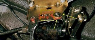
As can be seen in the diagram, contacts 4 of the switch and resistor are closed and go to the plus of the motor. We have three wires coming out of the motor. Minus - black, blue-black and red - plus (soldered to one contact in the motor). Just in case, I replaced the short red wire with a longer one (longer than the blue-black one). It will go to the switch, and the blue-black one will go to the resistor (fourth contacts). If you disassemble the motor, mark the cover.
In the place where the resistor stood, cut out a rectangle for the new resistor. In order not to pull the wires through the top of the stove, next to the resistor, where the niche is protected from the fan, we drill a hole and stretch the wires. We make a harness of three wires for contacts 1, 2 and 3.
On the switch, pins 1 and 2 are smaller than the others. Here, where the upper arms are, there is an unnecessary block (for the headlight cleaner). I cut it off and collected all the wires. You can buy it if you wish. Black-blue to 4, and with a harness, respectively, 1, 2, 3. To pin 5 of the switch (in the center), connect the yellow-blue plus from the stove button at the very end when installing the console. I made the illumination of the levers separately, so we use the window illumination wires to illuminate the switch.
To install the switch, take out the original plug and trim the plastic a little on the right and left. We place the switch so that 0 is at the bottom, and the latches are on the right and left. An elastic band fits the frame, I don’t know why. I trimmed it and added speed marks with a stroke. I'll probably redo it in the summer. For illumination, I took a strip with 9 diodes, cut a slot, connected it to the wires from the backlight of another window (+/- not to be confused), and covered it with silicone. I hooked up the backlight of the original key so that the wires would not dangle:
Update dated 10/15/11, by AveGeo.
There is an inaccuracy in the article. The numbering of the heater motor switch terminals from Kalina does not coincide with the switch used in Shnivy.
The attached diagram shows the correct numbering.
In addition, this switch uses an LED for illumination, and its power supply plus is on the right when viewed from the rear.
For a comfortable climate, the car has a climate control system. Thus, it includes an electric motor, which in the summer takes air through a system of ducts from the street and supplies it to the cabin, and in the winter, through a system of air ducts and a radiator of the cooling system (popularly called a stove), it supplies warm air to the cabin
The electrical diagram for connecting the electric motor of the “stove” conventionally shows:
1 - fuse and relay in the mounting block, 2 - mode switch, 3 - circuit resistor, 4 - electric motor of the radiator of the interior heating system (stove), 5 - ignition switch. A - to the power source (battery)
The heating system in the cabin of the budget Lada Kalina model can significantly increase comfort for the driver and his passengers. It ensures that the required temperature conditions are maintained inside the car. Along with such useful options as:
- "ABS";
- airbag;
- electric power steering;
- electric front windows;
- front seat heating function,
The design of the interior heater allows the manufacturer to achieve a fairly acceptable level of equipment, which is very worthy for a small-class Lada Kalina model and makes it competitive among its rivals in this segment.
Heating system composition
The operating principle of the heater in the Lada Kalina is very simple. It is built on a supply and exhaust circuit. The heater circuit contains:
- cabin air filter;
- air ducts;
- heater radiator;
- electric fan;
- air flow and fan operating mode control module.
The design of the interior stove looks exactly like this, and is located behind the dashboard and only the system controls are present on its front surface in the Lada Kalina cabin. A running engine generates heat, which is removed from it by the cooling system. This circuit includes a heating radiator. The circulating liquid heats the honeycombs, from which the warm flow is directed into the cabin by means of a fan. Adjustment of the required temperature, strength and direction of the air stream is carried out using the handles and dampers present in the cabin. Sometimes the dampers need to be adjusted.
The air taken from the external environment initially passes through the intake element located on the hood at the bottom line of the windshield of the Lada Kalina. Next, the air rushes to the filter component and is supplied inside the cabin space by means of a fan.
The fan can operate in 4 different speed modes. The adjustment is carried out using the corresponding knob on the device, and the switching itself is possible due to the presence of a resistor block in the control module.
How to diagnose a heating system in Kalina?
Before performing a diagnostic procedure, you will need to carefully study the diagram. You should only try to check while the engine is running.
- The temperature regulator, located on the control unit in the cabin, is installed in the extreme left position. We activate the fan and observe hot air entering the cabin through the deflectors. Gradually moving the handle to the right until it stops, we reach the exit of the cold air stream.
- Checking the speed should begin by setting the appropriate knob to the minimum speed position. If the fan and its control module are working properly, then the force of the air stream should increase as the handle is moved to subsequent positions (and so on until the 4th speed mode, corresponding to the maximum number of revolutions).
- We check the dampers. Here we move the temperature level regulator to the maximum to the left position. We move the fan speed switch to the position corresponding to the 4th speed. The check itself boils down to smoothly moving the damper regulator between the extreme positions. This should be done in order to feel the adjustment in the direction of flow. By moving the temperature regulator to different positions, we observe a change in the degree of heating of the incoming air.
List of faults in the heating circuit
If the owner of LADA Kalina suspects the presence of any deviations from the normal functioning of the heating system, then the diagnostic procedures below will be required.
- The first step is to make sure that there is a sufficient amount of antifreeze in the cooling circuit.
- Next, check the integrity of the fuse.
- We make sure that the fan speed regulator is working properly.
- A weak air flow through the deflectors indicates the need to check the condition of the filter component.
- If there is no warm flow into the cabin when the engine is warm, then there may be air pockets in the cooling system or the dampers in the air ducts are jammed.
- A faulty temperature sensor will cause only hot or, conversely, cold flow to enter the cabin.
- Among the common reasons is depressurization of the LADA Kalina cooling system. Sometimes this may be due to the loss of tightness of the heater radiator itself. At the same time, antifreeze will enter the cabin, giving itself away as a specific smell and wet decorative floor covering. In order to detect a leak in a timely manner, it is necessary to monitor the level in the expansion tank frequently.
Diagram, instrument panel pinout
By the way, do you know how to apply these schemes in action?
All other schemes are suitable for Kalina 2 hatchback.
Electrical diagram of the car: 1 - right headlight; 2 — hood open sensor; 3 — sound signal; 4 - starter; 5 - battery; 6 - generator; 7 — windshield wiper gear motor; 8 — left headlight; 9 — right front door power window switch; 10 — motor-reducer for window lifter of the right front door; 11 — connection blocks to the right front speaker; 12 — electric drive for locking the lock of the right front door; 13 — windshield washer electric motor; 14 — ambient temperature sensor; 15 — block for connecting the wiring harness of the engine control system; 16 — electric drive for locking the left front door lock; 17 — brake fluid level sensor; 18 — connection blocks to the left front speaker; 19 — power window switch for the right front door, located on the driver’s door; 20 — left front door power window switch; 21 — door lock switch; 22 — motor-reducer for window lifter of the right front door; 23 — mounting block; 24 — control unit for the automobile anti-theft system; 25 — security alarm control unit; 26 — instrument cluster; 27 — right side turn signal; 28 — glove box lighting lamp; 29 — switch for the glove compartment lighting lamp; 30 — brake signal switch; 31 — ignition switch with transponder of the automobile anti-theft system; 32 — control unit for external lighting, instrument lighting and headlight beam direction control; 33 — steering column switch; 34 — left side direction indicator; 35 — connection blocks to the right rear speaker; 36 — electric drive for locking the right rear door; 37 — rear window heating switch; 38 — reverse lock switch; 39 — alarm switch; 40 — heater fan operating mode switch; 41 — additional resistor of the heater fan electric motor; 42 — heater fan electric motor; 43 — connection blocks to the left rear speaker; 44 — electric drive for locking the left rear door; 45 — electric fuel pump with fuel level indicator sensor; 46 — reverse light switch; 47 — parking brake warning switch; 48 — cigarette lighter; 49 — reverse lock solenoid; 50 — connection blocks to the head unit of the sound reproduction system; 51 — backlight lamps for the ventilation and heating system control unit; 52 — electric power steering control unit; 53 — interior lamp; 54 — right rear light; 55 — electric drive for locking the trunk lock; 56 — trunk light switch, built into the trunk lid lock; 57 — license plate lights; 58 - additional brake signal; 59 — rear window heating element; 60 — trunk light; 61 - left rear light. This diagram does not show the connection points and wiring harness terminals.
Instrument panel wiring harness
- instrument panel harness pads to the front harness;
- instrument panel harness pads to the rear harness;
- instrument panel harness pads to the front harness;
- instrument panel harness pads to the front harness;
- instrument panel harness pads to the front harness;
- instrument panel harness pads to the rear harness;
- mounting block contacts;
- mounting block contacts;
- mounting block contacts;
- mounting block contacts;
- *lighting control module;
- **instrument cluster;
- heater motor switch;
- instrument panel harness connector to the air intake box harness;
- ignition switch;
- car anti-theft system;
- instrument panel harness connector to the ignition system harness;
- cigarette lighter;
- hazard switch;
- rear window heating switch;
- brake light switch;
- switch for headlights and direction indicators;
- right steering column switch;
- windshield wiper and washer switch;
- horn switch;
- heater control panel backlight;
- illuminator;
- glove box lighting;
- glove box light switch;
- connectors for the instrument panel harness to the radio;
- connectors for the instrument panel harness to the radio;
- heater electric motor;
- additional resistance of the heater electric motor;
- electric power steering control unit;
- electric power steering control unit;
- A1, A2 – grounding points of the instrument panel harness;
- B – mounting block block.
The wires in this diagram have a letter designation of color and a designation of the number of the circuit element to which this wire is connected. The number of the block contact is indicated through the fraction.
Note: * – The electrical circuit diagram of the lighting control module is shown separately below. ** – The electrical circuit diagram of the instrument cluster is shown separately below.
Lighting control module
- A1 – wire lighting regulator;
- A2 – external lighting switch;
- A3 – rear fog lamp switch;
- A4 – headlight range control switch;
- HL1 – lamp for illuminating symbols;
- VD3 – LED indicator illumination;
- VD4 – LED indicator for rear fog lights.
Instrument cluster
Assignment of contacts of the instrument cluster block
Wiring diagram of the 1.4 l Lada Kalina engine control system (ECM)
Connection of the wiring harness of the engine control system (ECM) VAZ 11194 (1.4 l): 1 – ECU; 2 – block of the ECU wiring harness to the instrument panel; 3 – main fuse block; 4 – speed sensor; 5 – rough road sensor; 6 – oil pressure drop warning lamp sensor; 7 – throttle position sensor; 8 – coolant temperature sensor; 9 – coolant temperature indicator sensor; 10 – mass air flow sensor; 11 – idle speed regulator; 12 – electric fuel pump relay; 13 – fuel pump fuse (15A); 14 – ignition relay; 15 – ignition relay fuse (15 A); 16 – ECU power supply fuse (7.5A); 17 – crankshaft position sensor; 18 – control oxygen sensor; 19 – phase sensor; 20 – knock sensor; 21 – solenoid valve for purge of the adsorber; 22 – diagnostic oxygen sensor; 23 – ignition coil; 24 – spark plugs; 25 – nozzles; 26 – ignition coil harness block to the ECU; 27 – ECM wiring harness block to the ignition coil wiring harness; 28 – block of the ECM wiring harness to the injector wiring harness; 29 – block of the injector wiring harness to the ECM harness; A – to the positive terminal of the battery; B1, B2, B3 – grounding points of the ignition system harness; C1 – grounding point of the ignition coil wiring harness.
Description of the dashboard
The dashboard contains the following elements:
- Unit for controlling instrument lighting and external lighting.
- Horn switch.
- Switch for turn signals and headlights.
- Instrument cluster for Lada Priora.
- Lever for glass washer and wiper.
There is also an ignition switch on the instrument panel, which is combined with an anti-theft device. On the Lada Priora it has three positions. In addition, the instrument panel contains buttons and mechanisms such as a heated switch on the rear window, a clock, an alarm switch, a glove box lid, a tape recorder socket, an ashtray, a fan control unit, etc.
Tuning for the dashboard (dashboard) can be done with your own hands if you want to change the lighting for the instruments. In this case, the panel must be removed. The answer to the question: “How to remove the panel?” quite simple - using a screwdriver. Then we unscrew the fastening screws, disassemble the panel, remove the hands (you can use a knife, placing a piece of cardboard on the dial), and separate the cover from the plexiglass.
Replacing the dashboard backlight is done by scraping off (with a knife) the coating on the gasket numbers. If you want to leave them white (brighter), then you can put all the elements back together. However, many drivers want to make the instrument panel more informative. To do this, take a not very thick plastic bag with colored designs, from which parts of a certain color are cut out and glued to the back of the instrument panel. This way you can highlight, for example, areas of high speed on the speedometer, or “cold” areas on the temperature scale.
VAZ-2110 dashboard: pinout
Probably, hardly anyone will argue with the fact that the VAZ “ten” is not the pinnacle of design thought.
However, there is nothing surprising here, because this car was designed back in the last century. At the same time, the compensator, and quite a serious one, in this case is the price. In other words, a certain compromise is proposed - the imperfection of the car in exchange for an acceptable cost. Well, the choice is ultimately made by the car owner himself, deciding whether this option is suitable for him. You can talk about the advantages and disadvantages of this model for quite a long time. However, this is not what we will talk about now. Those who decide that the “ten” is a suitable option in terms of the ratio between price and quality often want to somewhat refine their iron horse during operation, making changes to both the exterior and the interior.
If we talk about tuning the car interior, then one of the main objects of improvement here is the dashboard. Many people simply don’t like the native version, which, frankly, doesn’t look very attractive. Yes, after the “Zhiguli” this is an undoubted step forward, but it’s already the 21st century outside the window, and I want something more beautiful and pleasing to the eye.
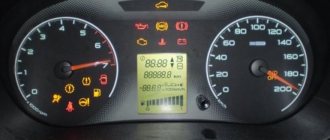
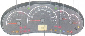
Additional indicators on the panel
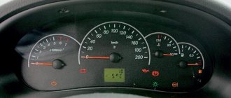
The LCD display on the panel displays information from the on-board computer. The open door indicator glows red if one of the doors is not closed. The low fuel indicator indicates the need to refuel (ignoring this signal may lead to failure of the fuel pump).
The weak tire indicator illuminates when tire pressure is low. If the driver is not wearing a seat belt, the seat belt sensor lights up. The airbag status indicator lights up in cases of system malfunction; you must contact a service station, since the airbag may inflate randomly. If any indicator fails, you can ring the system and find the reason; the pinout of the instrument panel will help with this.
Why you should know the pinout
But before you start this kind of upgrade, you need to understand which wire leads where. The pinout of the instrument panel of a VAZ-2110 car is a very important point when “tuning”. Without this, you risk simply getting confused in a fairly large number of wires, buttons and various sensors. The pinout will be useful in any case - both when making minor improvements and when completely replacing the instrument panel.
The process of installation and dismantling itself is quite labor-intensive, but if you know the correct sequence of actions, then there is nothing particularly difficult about it.
For these works you will need a minimum set of tools - a screwdriver and pliers.
For those who are doing this for the first time, it is best to stock up on self-adhesive pieces of paper, like those on which prices are written in stores, and a pen. With their help, at the time of disassembly, you will indicate, firstly, the sequence of dismantling the parts, and secondly, which wire is connected where. At first glance, this may seem time-consuming, but in fact, for beginners, such markings will help them put the panel back together faster.
At the same time, before starting work, it is best to stock up on a pinout diagram - at least conditional. After all, during the work process you need not to confuse anything and correctly understand each wire and connection during the reassembly process. It is worth noting one very important point. By and large, understanding the pinout of the panel of the “tenth” family will not be difficult even for a beginner.
But you need to remember that there are certain differences here, depending on the plant where the car was manufactured and the year of its manufacture. For example, the instrument panel may be an old model, with a mechanical odometer. If the odometer is electronic, then this is a newer version. Accordingly, there are certain differences in pinout between these panels.
Ignition system diagram Lada Kalina Lux
1 — oil pressure warning lamp sensor; 2 — coolant temperature indicator sensor; 3 — additional fuse block; 4 — fuses for the electric fan of the engine cooling system; 5 — electric fuel pump relay; 6 — relay for the electric fan of the engine cooling system; 7 - ignition relay; 8 — relay 2 of the electric fan of the engine cooling system; 9 — relay 3 of the electric fan of the engine cooling system; 10 — electric fan of the engine cooling system; 11 — throttle position sensor; 12 — idle speed regulator; 13 — coolant temperature sensor; 14 — diagnostic block; 15 — ignition system harness block to the instrument panel harness block; 16 — solenoid valve for purge of the adsorber; 17 — speed sensor; 18 — ignition system harness block to instrument panel harness block 2; 19 — mass air flow sensor; 20 — crankshaft position sensor; 21 — oxygen sensor; 22 - controller; 23 — rough road sensor; 24 — diagnostic oxygen sensor; 25 — ignition coil harness block to the ignition system harness block; 26 — ignition coils: 27 — ignition system harness block to the ignition coil harness block; 28 — spark plugs; 29 — nozzles; 30 - resistor; 31 — air conditioning system pressure sensor; 32 — blocks of the ignition system harness and injector wiring harness; 33 - phase sensor; 34 - knock sensor.
Ignition system wiring harness -11184-3724026-10. Ignition coil wiring harness -1118-3724148-00. Injector wiring harness -11184-3724036. A - to the “plus” terminal of the battery.
Tell me, where can I get the pinout for the connector of the control unit for the “Lux” electrical package? I wanted to install a pager and a sensor, I found everything, took it apart - and there were 2 connectors, 20 thin and a second one, 10 thick. The third connector is not connected. THERE WAS a rumor that the block on the luxury ones was Priorovsky, but I also could not find a description of it, and besides, it is combined there with APS-6. There is no need to send it to the search, because... Finding anything on a new engine is almost unbelievably lucky
Well, no one installed an alarm on the luxury version? I downloaded the Priora diagram - the Priora block has 20 contacts and 2 more connectors, everything seems to fit together, but the Priora for the additional sensor has a 3-pin connector, and mine has this connector with about 8 - 10 contacts. And there is still no description.
Kalina stove switch pinout
Today we will tell you about such an interesting and useful modification as installing a heater switch from the Lada Kalina on a VAZ-2107 and on any classic. To implement this modification, we will need the heater switch itself from Viburnum, wires with terminals, and a heater resistor from either a Niva-Chevrolet or a VAZ-2110, which is preferable, purely structurally it is better. This modification allows us to significantly expand the range of speed control on our classic stove, which will provide certain convenience in winter in terms of minimizing the noise of the stove motor when the desired temperature is reached in the car interior. This is what the switch from the viburnum actually looks like, see the photo below:
Here it is paired with a stove resistor:
We need to disassemble the stove on our VAZ, namely, remove its lower part; how to remove it is described using the example of the article “how to remove the stove motor on a VAZ-2107” - see the link. So, we carefully cut out a hole of the appropriate size so that the resistor goes inside the stove and does not fall through, and we still have the opportunity to “screw” it. We did this on the driver's side, the left side closer to the partition, which is next to the engine compartment. The main thing is that the resistance is cooled by the air flow from the stove fan, otherwise it will burn out.
We stretch the wires, ideally tie a mini harness and connect our Kalinovsky stove regulator according to the diagram below:
The regulator itself was built into the panel with the cigarette lighter and the clock instead of the unnecessary brightness control for the instrument illumination; on the classic, this control looks more like a mockery or subtle trolling:
In general, convenient and practical. On a classic original heater motor, this modification allows you to somewhat expand the smoothness of the heater speed control, but if you install a snail or a heater motor from a VAZ-2108-2109, then this modification is simply necessary and it is many times more interesting than the banal use of a knob and resistor from a VAZ-2108 . Good luck to everyone on the roads!
With the onset of cold weather, the main task of every motorist is to create warm and comfortable living conditions in the car. After all, you will agree that it is much more comfortable to drive in a warm car than to be cold. However, if heat is not supplied, then it is necessary to figure out what could be causing this. In this article I want to talk about repairing the Kalina stove switch.
The device of the stove adjustment mechanism
On the Lada Kalina car, the heater switches are located on a panel in the central part of the dashboard. It contains control mechanisms, namely:
- heater temperature regulator;
- fan operating mode regulator;
- air flow distributor control regulator;
- recirculation flap switch lever.
Actually, this is what our mechanism looks like. Now let's move on to possible causes of failure.
Main causes of malfunctions
So, what should we do if heat does not flow inside our car and cold air blows. Let's consider the main causes of such malfunctions:
- Failure of the Kalina heater switching control cable. The reason for such a malfunction may be that the latch has fallen off, and the cable stretches normally in one direction, but does not reach the opposite direction.
- On Kalina, the stove only works at speed 4. Associated with a broken thermistor.
- On a Kalina car, the heater switch often breaks when turned on abruptly, which is due to insufficiently strong plastic.
Here is a list of the main breakdowns that may occur. Next, we move directly to the repair itself and replacement of failed parts.
Repair and replacement of faulty parts
Many novice motorists ask questions: how to remove the heater regulator on Kalina, what LED is in the heater switch on Kalina, what should be done when the heater mode switch on Kalina does not work. Answering these questions, I want to say that initially it is necessary to dismantle our entire mechanism, after which we proceed to disassembly according to the following scheme:
- First of all, disconnect the negative terminal from the battery. This is done to de-energize the system so as not to short-circuit any of the sensors during the disassembly process.
- We remove the radio and turn off the power coming from the wiring harness.
- We remove the damper switch lever, then remove the temperature regulator and the air flow distribution regulator.
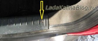
- At the bottom, remove the plugs behind which there are 2 screws, unscrew the fastening screws and gradually begin to remove the instrument panel console.
- After our panel is removed, it is necessary to disconnect the power supply connectors located on the back.
- After eliminating the malfunction, assembly is carried out in the reverse order.
What does the dashboard consist of?
The Priora instrument panel contains all the necessary parts that no modern car can do without:
- regulator of external lighting and internal panel lighting;
- switch for turning, side and headlights;
- signal regulator;
- car instrument cluster;
- windshield wiper and washer regulator.
This is how the dashboard works
In addition, the panel contains an ignition switch connected to the anti-theft system. It contains 3 positions. Among the secondary mechanisms, we can note the presence of regulators for the rear window heating system, alarm and interior cooling. It is also worth mentioning the glove compartment, built-in clock and radio input jack.
Features of connecting BC
In conclusion, I would like to dwell in more detail on such a point as installing an on-board computer. In the typical pinout diagram shown just above, there is only one wire leading to it - brown. But for the correct operation of this device, this alone will not be enough. Therefore, here is a complete pinout diagram for connecting the on-board computer:
- Green wire – comes from the electronic control unit, needed to obtain information about fuel consumption.
- Orange – goes to the ignition switch, to terminal 15.
- White-red - in the same place, only to terminal 30.
- The common ground wire is black.
- Brown – needed to take speed data.
- Red-green - to the positive circuit of the fuel level sensor.
- White - leads to the light control, which is responsible for the lamps that illuminate the instrument panel.
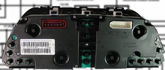
Which wire goes where?
First, let's look at the back of the instrument panel. At the top there are:
- fuel level indicator;
- dashboard lighting lamps;
- control of right and left turns (separately);
- tachometer;
- block with many plugs;
- coolant temperature gauge.
As you can see, there is really nothing particularly complicated here. At the bottom of the instrument panel on the back side there are controllers:
- high beam;
- "emergency lights";
- CHECK ENGINE;
- battery charge;
- parking brake;
- oil pressure;
- air damper (for models with a carburetor);
- outdoor lighting work.
In addition, there is also a speedometer and a brake fluid level indicator lamp.
Now let's take a closer look at the pads. There are two of them - white and red. In the first, the connectors and wires look like this (in order):
- Ground wire black.
- Red-brown – low-voltage supply from the ECU to the tachometer.
- Yellow – high-voltage supply to the tachometer from the coil.
- Red-blue - comes from the battery through the 6th fuse Const with a voltage of 12 volts.
- Green-white - leads to the coolant temperature sensor.
- Green-yellow – fuse F1, responsible for the side lights.
- This connector has no color, it goes to the throttle valve.
- Red and white – leading to the CHECK ENGINE indicator light.
- 2 orange wires leading to two F19 + 12 volt power fuses.
- Same as the previous connector.
- 2 blue-brown wires leading to the “VK” terminal of the handbrake.
- The output to terminal D of the generator is a brown-white wire.
- Gray and blue - wire going to the oil pressure sensor.