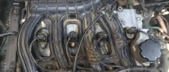
Why did it happen so?
Perhaps the automatic requests do not belong to you, but to another user accessing the network from the same IP address as you. You need to enter the characters into the form once, after which we will remember you and be able to distinguish you from other users exiting from this IP. In this case, the page with the captcha will not bother you for quite a long time.
You may have add-ons installed in your browser that can make automatic search requests. In this case, we recommend that you disable them.
It is also possible that your computer is infected with a virus program that is using it to collect information. Maybe you should check your system for viruses.
Contactless ignition of vases (2101-2107). complete installation guide - AutoSovet
Now almost all classic owners install contactless electronic ignition (BSI) on their cars. And it's easy to explain. BSZ has obvious and proven advantages, such as simplicity and ease of configuration.
If you are already quite tired of the fact that the contact pair, for certain reasons, very often does not work or even fails.
You have not yet decided whether to buy a contactless ignition kit, then this article will help you make the right choice.
Now, let's move on to the most important thing - choosing and installing BSZ on your car.
I think that it is best to opt for a contactless ignition kit made in Russia, namely the city of Stary Oskol.
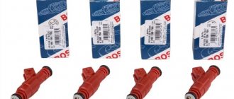
The box contains a coil, switch, wiring harness and distributor. This kit is considered one of the best.
For installation, we will need a drill, a drill and a pair of screws; they will be useful for installing the coil in the engine compartment; some engines have a standard mounting location, but you will have to attach the switch yourself. An open-end wrench for “13”, socket or ring wrenches for “8” and “10”, as well as a wrench for “38” are also useful.
Description of SZ on UAZ
How is the ignition circuit installed, configured and adjusted on the AUZ 417 or any other? We will talk about this below. But first, let's understand the principle of operation of the node, as well as the types of SZ.
Operating principle of SZ
As already said, the ignition on an UAZ performs one of the main functions when starting the power unit. Thanks to this system, the procedure for igniting the air-fuel mixture in the cylinders of the power unit is carried out by supplying a spark. The spark is directly supplied to the spark plugs; one spark plug is installed on each cylinder. All of these safety devices operate in sequence mode, igniting the combustible mixture in the required period of time. It is also necessary to take into account that the ignition system on cars not only provides a spark, but also determines its strength.
The vehicle battery is not able to produce the voltage and current required to ignite the mixture, since this device only produces a certain amount of current. The help comes from the ignition system, the purpose of which is to increase the power of the car’s battery. As a result of using the SZ battery, it is possible to transmit sufficient voltage to the spark plugs to ignite the mixture.
Types of ignition systems
Today there are three main types of ignition systems that can be installed on cars:
- Contact SZ. It is considered obsolete, but continues to be successfully used on domestically produced vehicles. The principle of operation is that the system produces the necessary impulse, which appears due to the operation of the distribution component. The contact-type device itself is simple, and this is a plus, because in the event of a breakdown, the driver can always diagnose and repair it himself. The cost of replacement components is not high. The main components of a contact type system are a battery, a short circuit, a drive, spark plugs, a capacitor, and a breaker with a distributor.
- A non-contact ignition system called transistor. Many vehicles are equipped with this type. When compared with the type described above, the system is characterized by a number of advantages. Firstly, the generated spark has greater power, which is due to the increased voltage level in the secondary winding of the ignition coil. Secondly, the contactless system is equipped with an electromagnetic device that allows for stable operation, as well as energy transfer to all nodes. As a result, with proper tuning of the internal combustion engine, this allows not only to increase operating power, but also to save fuel. Thirdly, it is convenient in terms of node maintenance. To ensure long-term performance, after setting up and installing the distributor drive, this element must be lubricated from time to time. To ensure normal operation, the element is lubricated every ten thousand kilometers. As for the disadvantages, it is the difficulty of repair. It is impossible to repair the device yourself; this requires special diagnostic equipment, which is only available at service stations.
- Another option for SZ is electronic, which is the most technologically advanced and expensive today, which is why new vehicles are equipped with it. Unlike the two systems described above, the electronic ignition system is characterized by a complex device that ensures the functionality of not only the torque, but also other parameters. Currently, all modern cars are equipped with electronic systems. The key advantage is a more simplified procedure for setting the advance angle, as well as the absence of the need to periodically check the contacts for oxidation. In practice, the air-fuel mixture in engines with electronic combustion almost always burns completely. This type also has its disadvantages, in particular in the matter of repairs. It is impossible to produce it with your own hands, since this requires equipment. Detailed instructions for adjusting the ignition using a light bulb are presented in the video below.
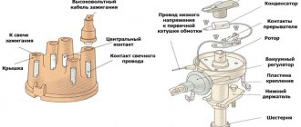
Reel design and operation
The modern bobbin is a simplified version of the Ruhmkorff induction coil. It was named after the German-born inventor Heinrich Ruhmkorff, who was the first to patent a device in 1851 that converts low-voltage direct voltage into high-alternating voltage.
To understand the principle of operation, you need to know the structure of the ignition coil and the basics of radio electronics.
This is a traditional, common VAZ ignition coil, used for a long time and on many other cars. In fact, this is a pulse high-voltage transformer. On a core designed to enhance the magnetic field, a secondary winding is wound with a thin wire; it can contain up to thirty thousand turns of wire.
On top of the secondary winding is a primary winding made of thicker wire and with fewer turns (100-300).
The windings at one end are connected to each other, the second end of the primary is connected to the battery, the secondary winding with its free end is connected to the voltage distributor. The common point of the coil winding is connected to the voltage switch. This entire structure is covered by a protective housing.
A direct current flows through the “primary” in the initial state. When a spark needs to be formed, the circuit is broken by a switch or distributor. This leads to the formation of high voltage in the secondary winding. Voltage is supplied to the spark plug of the desired cylinder, where a spark is formed, causing combustion of the fuel mixture. High-voltage wires were used to connect the spark plugs to the distributor.
The single terminal design is not the only one possible; there are other options.
- Double spark. The dual system is used for cylinders that operate in the same phase. Let's assume that compression occurs in the first cylinder and a spark is needed for ignition, and in the fourth cylinder there is a purge phase and an idle spark is formed there.
- Three-spark. The principle of operation is the same as that of a two-terminal one, only similar ones are used on 6-cylinder engines.
- Individual. Each spark plug is equipped with its own ignition coil. In this case, the windings are swapped - the primary is located under the secondary.
Setting the ignition timing
The ignition system is a very sensitive unit that requires careful adjustment. Only in this case can you achieve optimal engine performance, minimum fuel consumption and maximum possible power.
Methods for setting the ignition angle
You can adjust the ignition timing in different ways.
- Aurally.
- Using a light bulb.
- By strobe light.
- By spark.
The choice of method depends primarily on the availability of the necessary equipment and available tools.
Adjusting the ignition by ear
This method is distinguished by its simplicity, but it is recommended only for experienced car enthusiasts. The work is carried out with the engine warm and running in the following sequence.
- Loosen the nut securing the distributor and begin to rotate it slowly.
- Find the position of the distributor at which the engine speed will be maximum. If the position is found correctly, then when you press the accelerator pedal, the engine will quickly and smoothly gain speed.
- Stop the engine, turn the distributor 2˚ clockwise and tighten the fastening nut.
Adjusting the ignition using a light bulb
You can adjust the ignition of the VAZ 2107 using a 12V light bulb (car “control”). This is done as follows.
- The first cylinder is installed in a position where the mark on the crankshaft pulley will coincide with the 5˚ mark on the cylinder block. To turn the crankshaft you will need a special key.
- One of the wires coming from the light bulb is connected to ground, the second to the contact of the coil “K” (low voltage circuit).
- Loosen the distributor and turn on the ignition.
- By rotating the distributor, look for the position at which the light comes on.
- Tighten the distributor fastening.
Adjusting the ignition using a strobe light
Connecting the strobe and setting the ignition timing is carried out in the following order:
- The engine is warmed up to operating temperature.
- The tube is removed from the vacuum corrector, and a plug is installed in the resulting hole.
- The power wires of the strobe are connected to the battery (red - positive, black - negative).
- The remaining wire (sensor) of the device is fixed to the high-voltage wire going to the first spark plug.
- The stroboscope is installed so that its beam hits the crankshaft pulley parallel to the mark on the timing cover.
- Start the engine and loosen the distributor.
- By rotating the distributor, ensure that the beam jumps exactly at the moment it passes the mark on the crankshaft pulley.
Video: adjusting the ignition using a strobe light
The operating order of the VAZ 2107 engine cylinders
The VAZ 2107 is equipped with a gasoline, four-stroke, four-cylinder, in-line engine with an overhead camshaft. In some cases, to diagnose and troubleshoot problems, it is necessary to know the operating sequence of the cylinders of the power unit. For the VAZ 2107, this sequence is as follows: 1 - 3 - 4 - 2. The numbers correspond to the cylinder numbers, and the numbering starts from the crankshaft pulley.
The numbering of the VAZ 2107 engine cylinders starts from the crankshaft pulley
Setting the slider direction
With properly adjusted ignition, the engine and ignition system elements must be set in accordance with certain rules.
- The mark on the crankshaft pulley should be located opposite the 5˚ mark on the cylinder block.
- The distributor slider should be directed to the contact of the distributor cap corresponding to the first cylinder.
When the ignition is correctly adjusted, the distributor slider should be directed towards the contact of the cover corresponding to the spark plug of the first cylinder
Thus, adjusting the ignition timing of the VAZ 2107 is quite simple. Even an inexperienced car enthusiast with a minimum set of tools and carefully following the instructions of specialists can do this. At the same time, one should not forget about safety requirements, since most of the work involves high voltage.
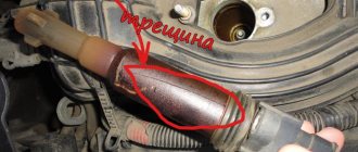
How to carry out repairs
If a breakdown is detected, the damaged coil must be removed. To complete the work you will need a set of wrenches.
After installing the new module, engine operation is checked; additional ignition settings are not required.
Removing the module
To remove a faulty unit, you will need:
- Disconnect the battery from the on-board network and remove the air filter housing.
- Disconnect the high-voltage cables and wiring harness.
- Remove the 3 nuts that hold the assembly to the mounting pad.
Replacement features
You can install the coil without using a special tool. The ignition system of injection engines does not require any adjustments. The throttle position is adjusted in idle and maximum gas modes. In case of malfunctions, it is necessary to check and align the crankshaft position sensor to the marks on the drive pulley of external units.
What causes an incorrectly set ignition on a VAZ 2107
An incorrect lead angle causes the following problems:
Engine overheating. Early ignition causes detonation, which changes the temperature regime of the engine. At the same time, the load on the crank mechanism increases, reducing their service life.
Reduced vehicle dynamics. Early and late ignition of the VAZ 2107 leads to the fact that fuel energy is not optimally consumed. The explosion of the mixture must occur exactly when the piston is at TDC.
Burnout of valves. With late ignition, the mixture continues to burn throughout the exhaust phase, causing the valves to overheat and “popping” to occur in the exhaust manifold.
How to check the ignition coil of a VAZ
If the ignition coil is faulty, the engine will not start. A characteristic sign of a faulty coil is its increased temperature when the ignition is turned off. This is easy to determine by touch.
Signs of a faulty ignition module may include the following:
- hesitant engine starting or failure to start;
- failures during sudden changes in speed;
- high fuel consumption;
- two cylinders do not work, the engine is feverish;
- lack of dynamics;
- a sharp drop in power;
- drop in power and thrust after warming up.
These symptoms may not only be caused by the ignition module. To determine the malfunction, it is enough to spend a few minutes diagnosing spark plugs, high-voltage wires and caps. This will eliminate the remaining elements of the ignition system and make sure that it is the ignition module that is faulty.
Checking the ignition coil is performed in one of 2 ways. The simplest one is to remove the central wire from the breaker-distributor, bring it to the motor housing and turn it with the starter, and a running spark should appear. After this, we check the energy supply to a separate spark plug, for which we unscrew the working spark plug, bring its contact to ground and attempt to start the engine. In this case, the spark should come from the wire to ground. If it is absent, the reason will be a malfunction of a system element such as the ignition coil.
To check the module in the second way, we only need a multimeter, then follow the step-by-step instructions:
- We check the power supply and the presence of pulses supplied from the ECU. We check the power between the central terminal (15) of the wire block connected to the module and the engine ground. When the ignition is on, the voltage should not be less than 12 V. Otherwise, either the battery is dead or the ECU does not work.
- We check the pulses from the ECU on the wiring block. We install one tester probe on connector 15, the second on the far right, then on the far left. The assistant cranks the engine with the starter, and at this time we record short-term voltage surges with a tester. If there are no impulses from the ECU, it is he who is to blame.
- We check the resistance on the secondary windings of the coils. We put the tester in resistance measurement mode and measure it at the high-voltage terminals of the module cover. Between pins 1 and 4 and pins 2-3, the resistance should be 5.4 kOhm. Otherwise, the module must be replaced.
- We check the resistance of the primary windings between contacts 15 and the rightmost, then the leftmost terminals. Nominal - 0.5 Ohm. Deviation is not allowed.
- Check the module for a short circuit. In ohmmeter mode, install one multimeter probe on the central terminal, the second on the metal body. There shouldn't be any resistance. If the device detects at least some resistance (other than unity or infinity), the module must be replaced.
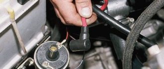
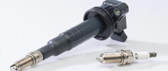
Spark plug
Plugs are used to ignite the fuel-air mixture in the engine cylinders when high voltage is supplied from the ignition coil. The main elements of any spark plug are a metal body, a ceramic insulator, electrodes and a contact rod.
Spark plugs are necessary to generate a spark and ignite the fuel-air mixture in the engine cylinders
Checking spark plugs for VAZ 2107
There are many ways to check spark plugs. The most popular are the following algorithms.
- With the engine running, remove the high-voltage wires one by one and listen to the operation of the engine. If after disconnecting the wire no changes occur, then the corresponding spark plug is faulty. This does not mean that it necessarily needs to be changed. In some cases, you can get by with cleaning it.
- The spark plug is unscrewed and a high-voltage wire is put on it. The spark plug body is leaned against a mass (for example, a valve cover) and the starter is cranked. If the part is working properly, the spark will be clear and bright.
- Sometimes spark plugs are checked with a special tool - a gun. The spark plug is inserted into a special hole and checked for the presence of a spark. If there is no spark, the spark plug is faulty.
- Candles can be checked with a homemade device made from a piezo lighter. The wire from the piezo module is extended and attached to the tip of the candle. The module is pressed against the spark plug body and the button is pressed. If there is no spark, replace the spark plug with a new one.
Video: checking spark plugs
Selection of spark plugs for VAZ 2107
Various models of spark plugs are installed on VAZ 2107 carburetor and injection engines. In addition, the parameters of the spark plugs depend on the type of ignition system.
The choice of spark plugs for the VAZ 2107 is determined by both the ignition system and the engine type
Auto stores offer many types of spark plugs for the VAZ 2107, differing in technical characteristics, quality, manufacturer and price.
Table: characteristics of spark plugs depending on the type of VAZ 2107 engine
| For carburetor engines with contact ignition | For carburetor engines with contactless ignition | For injection 8-valve engines | For injection 16-valve engines | |
| Thread type | M 14/1.25 | M 14/1.25 | M 14/1.25 | M 14/1.25 |
| Thread length, mm | 19 mm | 19 mm | 19 mm | 19 mm |
| Heat number | 17 | 17 | 17 | 17 |
| Thermal enclosure | Stands for spark plug insulator | Stands for spark plug insulator | Stands for spark plug insulator | Stands for spark plug insulator |
| Gap between electrodes, mm | 0.5 – 0.7 mm | 0.7 - 0.8 mm | 0.9 – 1.0 mm | 0.9 – 1.1 mm |
You can install spark plugs from various manufacturers on VAZ cars.
Table: manufacturers of spark plugs for VAZ 2107
| For carburetor engines with contact ignition | For carburetor engines with contactless ignition | For injection 8-valve engines | For injection 16-valve engines |
| A17DV (Russia) | A17DV-10 (Russia) | A17DVRM (Russia) | AU17DVRM (Russia) |
| A17DVM (Russia) | A17DVR (Russia) | AC DECO (USA) APP63 | AC DECO (USA) CFR2CLS |
| AUTOLITE (USA) 14–7D | AUTOLITE (USA) 64 | AUTOLITE (USA) 64 | AUTOLITE (USA) AP3923 |
| BERU (Germany) W7D | BERU (Germany) 14–7D, 14–7DU, 14R-7DU | BERU (Germany) 14R7DU | BERU (Germany) 14FR-7DU |
| BOSCH (Germany) W7D | BOSCH (Germany) W7D, WR7DC, WR7DP | BOSCH (Germany) WR7DC | BOSCH (Germany) WR7DCX, FR7DCU, FR7DPX |
| BRISK (Czech Republic) L15Y | BRISK (Italy) L15Y, L15YC, LR15Y | CHAMPION (England) RN9YC | CHAMPION (England) RC9YC |
| CHAMPION (England) N10Y | CHAMPION (England) N10Y, N9Y, N9YC, RN9Y | DENSO (Japan) W20EPR | DENSO (Japan) Q20PR-U11 |
| DENSO (Japan) W20EP | DENSO (Japan) W20EP, W20EPU, W20EXR | EYQUEM (France) RC52LS | EYQUEM (France) RFC52LS |
| NGK (Japan/France) BP6E | EYQUEM (France) 707LS, C52LS | MARELLI (Italy) F7LPR | MARELLI (Italy) 7LPR |
| HOLA (Netherlands) S12 | NGK (Japan/France) BP6E, BP6ES, BPR6E | NGK (Japan/France) BPR6ES | NGK (Japan/France) BPR6ES |
| MARELLI (Italy) FL7LP | MARELLI (Italy) FL7LP, F7LC, FL7LPR | FINVAL (Germany) F510 | FINVAL (Germany) F516 |
| FINVAL (Germany) F501 | FINVAL (Germany) F508 | HOLA (Netherlands) S14 | HOLA (Netherlands) 536 |
| WEEN (Netherlands/Japan) 121–1371 | HOLA (Netherlands) S13 | WEEN (Netherlands/Japan) 121–1370 | WEEN (Netherlands/Japan) 121–1372 |
Installation of BSZ on VAZ 2106
When choosing a contactless ignition kit, pay attention to the engine size of your “six”. The distributor shaft for a 1.3 liter engine should be 7 mm shorter than for more powerful 1.5 and 1.6 liter power units. To install BSZ on a VAZ 2106 car, you should prepare the following set of tools:
To install BSZ on a VAZ 2106 car, you should prepare the following set of tools:
- open-end or socket wrenches with dimensions of 7-13 mm;
- flathead and Phillips head screwdrivers;
- pliers;
- drill with a 4 mm drill (to mount the electronic unit in the side member you will have to make 2 holes for self-tapping screws).
I highly recommend purchasing a 38 mm socket wrench with a long handle for unscrewing the ratchet. It is inexpensive, around 150 rubles, and is useful in many situations. Using this key, it is easy to turn the crankshaft and set pulley marks to adjust the ignition and timing.
The first step is to dismantle the old system - the main distributor and coil:
- Pull out the high-voltage wires from the sockets of the distributor cover and disconnect it from the body by unlocking the latches. Dismantling old equipment begins with disassembling the distributor - removing the cover and wires
- When turning the crankshaft, set the slider at an angle of approximately 90° to the engine and place a mark on the valve cover opposite. Unscrew the 13 mm nut securing the distributor to the block. Before removing the ignition distributor, mark the position of the slider with chalk
- Unscrew the clamps of the old coil and disconnect the wires. It is advisable to remember the pinout or sketch it. The wire terminals are connected to the transformer contacts on threaded clamps
- Loosen and unscrew the nuts securing the clamp, remove the coil and distributor from the car. The distributor housing is attached to the cylinder block with a single 13 mm wrench nut.
When removing the ignition distributor, keep the washer-shaped gasket installed between the part platform and the cylinder block. It may be useful for a contactless distributor.
https://www.youtube.com/watch?v=BxzbLbvo1qc
Install the contactless kit according to the instructions:
- Remove the BSZ distributor cap and, if necessary, replace the sealing washer from the old spare part. Turn the slider to the desired position and insert the distributor shaft into the socket, lightly pressing the pad with a nut. Before installing the distributor into the socket, turn the slider towards the chalk marks drawn on the valve cover
- Replace the cover, securing the latches. Connect the spark plug cables according to the numbering (the numbers are indicated on the cover).
- Screw the coil of the contactless system to the body of the VAZ 2106. To ensure that terminals “B” and “K” are in their original position, first unfold the body of the product inside the mounting clamp. When installing the coil, connect the wires from the ignition relay and tachometer
- Place the wires from the ignition switch and tachometer onto the contacts according to the diagram above.
- Install the controller next to the spar by drilling 2 holes. For convenience, remove the expansion tank. The controller is attached to the holes in the side member using self-tapping screws
- Connect the wiring harness to the distributor, switch and transformer. The blue wire is connected to terminal “B” of the coil, the brown wire is connected to terminal “K”. Place a high-voltage cable between the distributor cover and the central electrode of the transformer. The spark plug cables are connected according to the numbering on the cover, the central wire is connected to the coil electrode
If there were no annoying mistakes during the installation process, the car will start immediately. The ignition can be adjusted “by ear” by loosening the distributor nut and slowly turning the housing at idle engine speed. Achieve the most stable operation of the motor and tighten the nut. Installation is complete.
DETAILS: Installation and repair of wipers on a VAZ 2107
Connecting and replacing VAZ short circuit
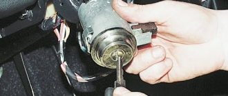
The procedure for removing and installing the ignition coil on old VAZ models:
- First, disconnect the central high-voltage wire leading to the distributor (ignition distributor).
- Disconnect all power wires from the coil contacts. Since they are fastened with nuts, you will need an 8 wrench for this.
- If you don’t know which wires to connect to which connector later, it’s better to immediately remember or mark them somehow, so that later during installation you can connect them correctly.
- Unscrew the coil housing. It is attached to a clamp (clamp), which is pressed to the car body with two nuts.
- After the work has been done, you can remove the ignition coil and replace it if necessary.
For new type VAZ cars:
- We remove the “minus terminal” from the battery.
- Remove the top protective cover of the engine. If the engine volume is 1.5 liters, then this part is missing and this step is skipped.
- We remove the high-voltage wires from the coil.
- Now, using a 13mm wrench, unscrew the two fasteners.
- Using a 17mm wrench, loosen one bolt securing the coil.
- We take out the module.
- Use a hexagon to unscrew the coil from the holder.
- Assembly is carried out in reverse order.
Particular attention should be paid to the connection, since high-voltage wires must be located in the strict order provided for by the design. If this is not done, the car will stall or the engine may not start at all.
Replacing the ignition coil on a VAZ is quite simple. Even a novice motorist can do this in his garage, and if everything seems too complicated, contact a car service center. Particular attention should be paid to the choice of product, since this will determine how well the engine and ignition system will work.
Is there a difference between contact and electronic ignition?
On carburetor VAZ 2107, both an electronic and a contact device were installed. The adjustment process is no different. The only difference may be that before setting the marks, it is necessary to clean the contacts on the contact breaker and check the gap so that the system can be adjusted more accurately.
How to adjust the ignition: early or late ignition
By the way, many people mistakenly call the switch the ignition relay. This relay is only a way to reduce the inrush current and is designed to preserve the life of the contacts. This relay is located in the engine compartment. The ignition setting does not apply to it.
This is how you can adjust the ignition on a carburetor VAZ 2107. Good luck on the roads!
Owners of VAZ classics with a carburetor engine are aware of its imperfect ignition system, with which difficulties often arise. Models with an injection engine are equipped with a different system called contactless. To avoid difficulties with a carburetor engine, a contactless ignition system is installed on the VAZ 2107. How the system works and how to install it on a VAZ 2107 is described in the material.
Design and principle of operation of the BZ
Contactless or electronic ignition on the VAZ 2107 is installed on models with injection engines. Carburetor sevens were supplied from the factory with contact ignition systems, which have many disadvantages. If you plan to install a contactless ignition module, then before starting it won’t hurt to understand the issue of its design.
The ignition system is the mechanism by which a pulsed voltage is created to supply the spark plugs in order to promptly ignite the fuel-air mixture in the cylinders. The main disadvantage of contact SZ is that the contact groups require regular cleaning, replacement and adjustment. As soon as difficulties arose with igniting the combustible mixture, the car owner immediately knew where to look for the reasons.
With the advent of the BSZ, these difficulties automatically disappeared. To understand why, let’s look at the components of the mechanism:
- Electronic type switch with transistors.
- Double winding coil.
- A distributor or distributor equipped with a Hall sensor, a slider and a contact cover.
- Spark plugs with armored wires.
The BSZ diagram for the VAZ 2107 is shown in the photo below.
Based on this diagram, let's consider the principle of its operation:
- When you turn the ignition key, current is supplied to the primary winding of the coil, thereby creating a magnetic field.
- When the engine starts, power is supplied to the starter coil and the rotor begins to turn the crankshaft.
- In this case, the crankshaft rotates the distributor shaft, which is connected to the runner.
- As soon as the shaft with the slider rotates, this phenomenon is detected by the Hall sensor (along the protrusion on the shaft) and transmits the corresponding signal to the switch.
- When a signal arrives at the switch, the primary winding of the coil is de-energized (on the low-voltage side).
- A powerful discharge of about 25-30 kV is induced in the secondary (high-voltage) winding, transmitted to a moving contact located at the end of the distributor shaft.
- When the slider moves in a circle, it practically touches the contacts in the cover, a spark occurs between them, and a high voltage discharge is transmitted to each of the contacts in turn.
- This discharge flows through armored cables to the spark plug electrodes.
The mechanism in question received the name “contactless” due to the connection and disconnection of the circuit of the primary winding of the coil with a commutator due to the output transistor (without using contacts).
From the history of VAZ cars
Today, capacitor failure is an extremely rare occurrence and many do not even know about its existence. When the power supply circuit for cars was with reverse polarity, i.e., the “plus” went to ground, then not a single driver went on the road without a spare capacitor. Since 1961, by order of the Automotive Industry, they began to attach a “minus” to the ground and drivers simply forgot about the capacitor.
Let's go back to the old-style distributor...
The distributor also has centrifugal and vacuum ignition timing regulators. The centrifugal regulator is located under the slider. These are two weights with springs, which, depending on the engine speed, partially turn it inside the slider, forcing the contacts to open a little earlier.
The vacuum regulator is made in the form of a vacuum chamber on the side of the distributor, connected to the central plate (moves on a bearing) on which the contacts are located. The vacuum, depending on the engine load, draws in the membrane, which is connected to the plate using traction, rotates it and the contacts also begin to open earlier.
The weak point of the contact distributor is the wear of the contacts and the breakage of the textolite tip of the contacts, thanks to which the distributor shaft opens the contacts. Burnout of the slider is also often observed when the current goes to ground. Less often, the bearing of the contact plate fails, and then unstable operation of the engine occurs.
Until 1987, the plates were installed on a bearing of small diameter, and since 1987 they began to install a bearing of larger diameter. Let's take a look at the video of a new type of contactless distributor:
The difference between the new sample distributor, a non-contact distributor, and a contact distributor is as follows. With a contact ignition system, the high voltage is about 13-18 thousand volts, and a contactless ignition system produces 35-40 thousand volts. A higher voltage ensures stable engine starting at any temperature, “dirty” spark plugs are not so critical for it, and the contactless ignition system is more economical.
There are no misfires due to the state of the breaker contacts, since this distributor simply does not have them. In addition, with a contactless ignition system, engine power increases, harmful emissions into the atmosphere are reduced, and due to higher voltage, fuel combustion is more complete. Externally, the distributors are similar and the only difference from the contact distributor is the plug input on the distributor body.
The contactless distributor is specially designed similar to the contact one so that it can be easily and simply replaced on the car. In a contactless distributor, the Hall sensor is responsible for supplying and interrupting high voltage or sparks to the candles, by analogy with front-wheel drive VAZ cars. To install contactless ignition on a car, in addition to the distributor, the kit also includes an ignition coil, a switch, spark plugs, and terminal blocks with connecting wires.
Some kits also include an EPHH unit (forced idle economizer). The Hall sensor has a permanent magnet, a microcircuit and a steel screen with slots. The sensor is fixedly fixed in the distributor, and a steel screen with slots is mounted on the distributor shaft. When a slot in a steel screen passes through the Hall sensor, a magnetic field is created and a voltage is created on the semiconductor wafer.
The sequence of slits on the steel screen creates low voltage pulses. A switch in contactless ignition is necessary to convert the control signal from the Hall sensor into high voltage pulses on the ignition coil.
On a distributor with contacts, the spark plug gap between the electrodes is 0.5-0.6 mm, and with electronic ignition 0.7-0.8 mm...
A car enthusiast familiar with auto electrics can easily install a kit for a contactless ignition system on his own. Those who feel that they can’t handle it are better to turn to auto electricians who can install it in the shortest possible time.
We briefly got acquainted with the distributors of the old (contact) and new (non-contact) models.
This is where I finish writing, friends. Good luck to you and see you soon on the pages of the RtiIvaz.ru blog!
Please read further:
Popular articles:
- Alternator drive belt for VAZ car
- How the valves of VAZ 2101-2107 are adjusted
- Would you like to know the sizes of the CV joint boots on the vase?
- VAZ timing belts on AvtoVAZ cars
- Door and trunk seals
- How to replace the silent block of the rear beam of VAZ cars
Non-contact ignition system device
The BSZ device for carburetor engines consists of:
- Distributor. This is a device that is responsible for creating a spark at the right moment. It is also called the ignition system distributor.
- High voltage coil. This element in the ignition system receives low voltage from the battery, converts it and supplies high voltage. Therefore, high-voltage wires come from it. The coil consists of two windings. The primary one is made of a large cross-section wire (connected to the electrical part of the car via the ignition switch relay), the secondary one is made of many turns of thin wire (connected with a high-voltage wire to the distributor).
- Switch. This element of the contactless ignition system is responsible for the formation of a spark. In simple words, a switch is a signal amplifier. The switch is only available in the ignition system of internal combustion engines with a carburetor. By the way, SOLEKS is considered the best carburetor. On injection VAZ 2107, as well as on others, a switch is not needed, since its functions are performed by the on-board computer controller.
- High voltage and normal wiring. High voltage wiring must meet heavy insulation requirements.
- Terminals. Serve for connections and must be strong.
Electronic and contactless ignition systems are the same device. It got its name due to the absence of a contact group in the system design. The ignition switch also has a contact group, which is a common cause of engine failure.
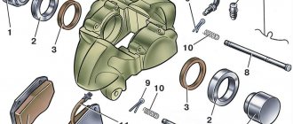
Distributor device:
- frame;
- shaft;
- cam;
- moving contact (slider).
Diagnostics of malfunctions of the ignition module of injection VAZ 2107
The ignition of the injection VAZ 2107 is completely electronic and is considered quite reliable. However, problems can arise with it too. The module plays an important role in this.
Signs of a malfunctioning ignition module
Symptoms of a faulty module include:
- the Check engine warning light on the dashboard lights up;
- floating idle speed;
- engine tripping;
- dips and jerks during acceleration;
- change in sound and color of exhaust;
- increased fuel consumption.
However, these signs can also appear in case of other malfunctions - for example, in case of problems with the fuel system, as well as in case of failure of some sensors (oxygen, mass air flow, detonation, crankshaft position, etc.). If the engine starts to operate incorrectly, the electronic controller puts it into emergency mode, using all available resources. Therefore, when the engine operation changes, fuel consumption increases.
In such cases, you should first of all pay attention to the controller, read information from it and decipher the error code that has occurred. To do this, you will need a special electronic tester, available at almost any service station.
If the ignition module fails, error codes in engine operation may be as follows:
- P 3000 - no sparking in the cylinders (for each cylinder the code may look like P 3001, P 3002, P 3003, P 3004);
- P 0351 - break in the winding or windings of the coil responsible for cylinders 1–4;
- P 0352 - a break in the winding or windings of the coil responsible for 2–3 cylinders.
At the same time, the controller can produce similar errors in the event of a malfunction (break, breakdown) of high-voltage wires and spark plugs. Therefore, before diagnosing the module, you should check the high voltage wires and spark plugs.
Main malfunctions of the ignition module
The main malfunctions of the VAZ 2107 ignition module include:
- a break or short to ground in the wiring coming from the controller;
- lack of contact in the connector;
- short circuit of the device windings to ground;
- break in the module windings.
Checking the ignition module
To diagnose the VAZ 2107 injection module, you will need a multimeter. The verification algorithm is as follows:
- Raise the hood, remove the air filter, find the module.
- We disconnect the block of the wiring harness coming from the controller from the module.
- We set the multimeter to measure voltage in the range 0–20 V.
- Without starting the engine, turn on the ignition.
- We connect the negative (usually black) probe of the multimeter to ground, and the positive one to the middle contact on the harness block. The device must display the voltage of the on-board network (at least 12 V). If there is no voltage or it is less than 12 V, the wiring or the controller itself is faulty.
- If the multimeter shows a voltage of at least 12 V, turn off the ignition.
- Without connecting the connector with wires, disconnect the high-voltage conductors from the ignition module.
- Switch the multimeter to resistance measurement mode with a measurement limit of 20 kOhm.
- To check the device for an open circuit in its primary windings, we measure the resistance between contacts 1a and 1b (the outermost ones in the connector). If the resistance of the device tends to infinity, there is indeed an open circuit in the circuit.
- We check the module for breaks in the secondary windings. To do this, we measure the resistance between the high-voltage terminals of the first and fourth cylinders, then between the terminals of the second and third cylinders. In operating condition, the module resistance should be about 5–6 KOhm. If it tends to infinity, the circuit is broken and the module is faulty.