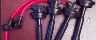
High-voltage ignition wires of the VAZ 2114 are part of the ignition system, through which an electrical impulse is transmitted from the module to the spark plugs. When the current hits the spark plugs, the fuel mixture ignites in the combustion cylinders, which gives rise to a new stroke of the engine.
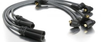
The design of the GDP, unlike conventional wires, is quite complex. In addition to the conductive core (which is made of copper) and protective insulation, they have metal tips and plastic protective caps.
Metal tips act as contacts; they fit into the sockets on the spark plugs and the ignition module. The durability of the GDP directly depends on how well the tips are made. When purchasing, be sure to check the strength of their attachment to the wire.
Features of connecting high-voltage wires to the VAZ 2114
High-voltage ignition wires of the VAZ 2114 are part of the ignition system, through which an electrical impulse is transmitted from the module to the spark plugs. When the current hits the spark plugs, the fuel mixture ignites in the combustion cylinders, which gives rise to a new stroke of the engine.
BB wires must be of high quality
The design of the GDP, unlike conventional wires, is quite complex. In addition to the conductive core (which is made of copper) and protective insulation, they have metal tips and plastic protective caps.
Metal tips act as contacts; they fit into the sockets on the spark plugs and the ignition module. The durability of the GDP directly depends on how well the tips are made. When purchasing, be sure to check the strength of their attachment to the wire.
I installed explosive wires with zero resistance, how did the operation of the motor change?
Many people remember from Soviet cars that their high-voltage wires had a good copper core. However, they were replaced by fashionable wires with a graphite core and silicone insulation in several layers. Many people praised these wires - they don’t tan, they don’t penetrate the insulation, the radio works without interference, and so on.
But, as they say, “the new is the well-forgotten old.” The network began to actively promote the idea of installing high-voltage wires with zero resistance.
People began to write that there was less resistance, a better spark, the car was speeding, it didn’t even smell the fuel, it just looked at it, the engine rustled, the 10-ruble coin stood on its edge and didn’t fall.
Before describing the emotions of the replacement, I suggest a little physics. In order for a spark to appear on the spark plug, it is necessary to break the distance between the electrodes. Accordingly, it is necessary to store as much energy in the ignition coil as is necessary for breakdown and to maintain the spark burning.
The resistance of the gap between the electrodes is about 60,000 kOhm, the resistance of a normal explosive wire should be about 5 kOhm, the ignition module also has an internal resistance of about 6 kOhm (on the injector) and a resistor in the distributor (resistance about 6 kOhm), if we are talking about a carburetor, also an additional resistor may be in the spark plug - this is about 5 kOhm more. Against the background of 60,000 kOhm, an additional 5-10 kOhm will not play a big role in the operation of a working ignition system. What is more important in this matter is the state of the gap at the spark plugs; it should not be too large or too small.
Moreover, I found a long time ago a study of spark plugs with and without resistors, where the manufacturer experimentally proved that fuel consumption with such spark plugs is even less, but when operating at a voltage of less than 9 volts (let’s say the generator stopped working), these spark plugs began to work a little worse.
Personally, I noticed absolutely no difference, provided that the spark plugs were A17 DVRM (with an additional resistor). The car was absolutely in good working order - a good battery, a new starter, spark plugs were changed every 20 thousand.
There was no difference when starting in winter, in the heat, in snow, in rain, and there was also no difference in fuel consumption or engine power. At first it seemed that the engine was running smoother, but this was more of a placebo effect and nothing more.
I think it’s pointless to believe in some kind of miracle, but there is an advantage.
The main advantage of such wires is their reliability and durability compared to purchased options, where the resistance variation from new can often exceed the permissible values. But a new kit lasts for two years at best (why would a manufacturer sell eternal explosive wires in a situation where there are fewer and fewer cars with a common ignition unit), while for a foreign car the kit can cost far less than 800 rubles.
WHICH GDP IS BETTER TO CHOOSE?
When choosing a GDP, two key factors must be taken into account - their resistance and breakdown voltage. The lower the resistance, the better the electrical impulse will be transmitted, and the magnitude of the maximum breakdown voltage determines how resistant the high-voltage wires on the VAZ 2114 will be to breakdowns.
The resistance value of products from different manufacturers differs from each other. As an example, we give you the resistance of the most popular types of GDP:
| Manufacturer | Resistance on cylinder No. 1 (kOhm) | Resistance on cylinder No. 2 | Resistance on cylinder No. 3 | Resistance on cylinder No. 4 | Breakdown voltage (kV) |
| Tesla | 3.27 | 4.16 | 5.02 | 6.26 | 50 |
| Cezar | 3.1 | 3.53 | 4.23 | 5.34 | 50 |
| Finwhale | 1.95 | 2.18 | 2.6 | 3.42 | 50 |
| Ween | 6.17 | 6.57 | 7.52 | 9.89 | 35 |
| Slon | 4.24 | 4.74 | 5.19 | 7.6 | 50 |
The products of the Czech company Tesla receive the largest number of positive reviews from the owners of the fourteenth. Their wires have optimal resistance and high breakdown voltage, and at the same time they are truly made to last - they do not tan or crack.
The cost of the Tesla GDP set is about 500 rubles, Cezar – 450 rubles, Ween – 270 rubles, Finwhale – 600 rubles, Slon – 500 rubles.
CONNECTION FEATURES
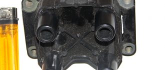
The order of connecting high-voltage wires must be strictly sequential, since each cylinder of the engine corresponds to a specific socket on the ignition module. Considering that there is a numbering of the sockets on the ignition module body, the risk of confusing anything is minimal.
The procedure for connecting high-voltage wires of the VAZ 2114 injection type depends on the year of manufacture of your car. Fourteeners before 2004 had 4-pin ignition modules installed, and cars after 2004 had 3-pin coils.
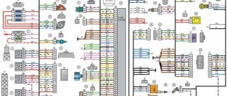
The connection diagram for VAZ 2114 high-voltage wires to the ignition module (until 2004) is as follows:
Connection diagram for VAZ-2114 with ignition coils (after 2004):
In the pictures you can see the numbers of the landing slots. Each number must have a corresponding cylinder connected to it (cylinder numbering is counted from left to right).
To correctly install high-voltage wires on the VAZ 2114, follow the following algorithm of actions:
- Turn off the ignition. Open the hood and remove the power terminals from the battery;
- We remove the old GDPs from the mounting sockets on the module and cylinders;
- We remember the location of the high-voltage wires of the VAZ 2114 and connect new GDPs according to the diagram. Before replacing, it would not be amiss to draw this very diagram by hand on paper so as not to confuse anything;
- We connect power to the battery and, to check whether we did everything correctly, start the engine.
When installing the wiring, do not try to connect individual air intakes to each other with plastic clamps; to do this, you must use the comb holder that comes with them. A thin clamp can easily wear through the insulating coating. Also make sure that the GDP does not bend.
Connecting armored wires on VAZ 2115 and 2113 is carried out in a similar way.
Sequence of actions to independently replace the ignition module on a Lada Grant
- We install wheel chocks on the rear row of wheels for safety purposes.
- Using a key set to “12”, unscrew the terminals from the battery. It is enough to turn off the negative power, but experts recommend both.
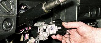
- In the center of the engine compartment we find the contact chip for the ignition module. It is held on by a special latch. We unclip it and take it out.
We detach the contact chip
- Disconnect the four high-voltage wires from the coil module. We hold it by the rubber base and remove it from its seat.
- By analogy, disconnect the remaining three wires.
Disconnecting the wires
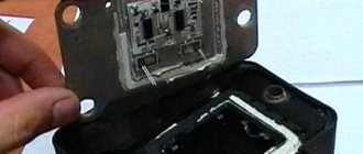
- Unscrew the four screws with a Phillips-head screwdriver and remove the ignition module of the Lada Granta 8-valve. It is placed on a metal bracket.
Removing the ignition module
- We remove the module.
Afterwards we carry out troubleshooting, diagnostics, and inspect the seat. We install the new module and assemble the mechanism in the reverse order.
Replacing the ignition module on the Lada Grant is completed.
HOW OFTEN SHOULD I CHANGE GDP?
According to the recommendations of Avto-VAZ, replacement of high-voltage wires of the VAZ 2114 should be done every 30 thousand kilometers. In practice, motorists rarely comply with these replacement deadlines, since if the wires do not have any mechanical damage, they can travel about 100-150 thousand km.
When the service life is exceeded, the internal resistance of the GDP increases, which negatively affects the transmission of the electrical impulse. This leads to problems with ignition and acceleration dynamics, since when the supply of current to the spark plugs is delayed, the normal engine operating cycle is disrupted.
Change the wires every 25-30 thousand km and everything will be fine
OPERATIONAL CHECK
To accurately determine whether it is time to change the high-voltage wires of the VAZ, you need to check their performance with a multimeter.
This operation will take you no more than 15 minutes:
- Turn off the ignition;
- We remove the wires: disconnect the first end from the ignition module, the second from the cylinder;
- We switch the tester to ohmmeter mode and connect the multimeter probes to the wire contacts.
If the high-voltage wires on the VAZ 2114 are in normal technical condition, the multimeter will show a resistance within the value indicated on the wire insulation; if the readings are different, the armored wires on the VAZ 2114 need to be replaced. The process must be repeated on each wire in turn.
How to check current leakage on a used car with a multimeter
The check includes:
- Turn off the engine, remove the key. Close the doors, but open the windows - the battery will not work continuously, and the car may be locked with a central lock.
- Make sure that the additional lighting and radio are turned off.
- Remove the negative terminal from the battery.
- Place one probe between the negative terminal and the negative terminal of the battery - the device will show the leakage current value.
The normal value is 15-70 mA. If the numbers are higher and you and the seller have time, try to find the reason. To do this, also connect a multimeter, then start removing the relays and fuses one by one.
The readings have returned to normal - you have found the cause of the current leak. Perhaps further repair or replacement of a part, or even the entire wiring, will be required. You can confidently ask the car seller for a discount or refuse the purchase altogether.
There may be several reasons for the leak. The following may be involved:
- battery;
- sensors;
- high voltage wires;
- generator.
Each element can be checked using a multimeter.
BB: what do they look like?
High-voltage wires VAZ 2114
Naturally, the technical conditions for the existence of working wires are the conditions of a permanent conductor. If we add here temperature changes and the imperfection of our world, we get the fact that the contact system fails within a certain period of time. And it comes with a frequency of 30,000 km.
This is a control figure that tells you when to change high-voltage wires. The fact is that over time, internal resistance begins to increase in them, preventing the impulse from passing as it should. In this case, you may notice the following behavior of the fourteenth:
- You want to press your sneakers to the floor, but the engine doesn’t respond
- The engine may simply stall
- At idle the engine troits
- It often happens that car owners themselves do not notice how high-voltage wires are pierced
Of course, this is not an indicator of a malfunction only in high-voltage equipment, but there is a high probability that it was they who flew. Surely, it is worth carrying out a test procedure for all contacts.
And the tester showed that the wires had a long life. Well, the high-voltage wires on the VAZ 2114 need to be replaced. The procedure, in principle, is not troublesome. If you were able to test them, then you can replace them. The main thing is to understand the order of connecting high-voltage wires.
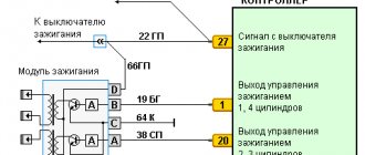
The fourteenth is an improved version of the nine, it has higher ignition power. Therefore, contacts have been added to the four high-voltage wires for connection to the ignition terminal itself, through which a signal goes to the spark plugs; Also, in the fourteenth system there are contacts leading to the switch, as well as contacts for connecting the adsorber valve to the gasoline injection system control unit.
The procedure for connecting high-voltage wires to a VAZ 2114
The connection diagram for high-voltage wires is quite simple:
- Cylinder 1 clings to the lower left contact
- Cylinder 2 clings to the upper left contact
- Cylinder 3 clings to the upper right contact
- Cylinder 4 clings to the lower right contact
This is sometimes called module bay interface in schematics. Essentially, everything is correct. The main thing is to understand that all cylinders are counted from left to right, like any count adopted from the logic of writing from left to right: 1,2,3,4. And the connection is obtained according to the following scheme: 1,3,4,2. Many people sketch and write down how the contacts were before removal. But, if you look at the module itself, there are docking numbers there. It's impossible to make a mistake.
What does P0301 mean?
P0301 (and other P030X codes such as P0302, P0303, etc.) are simpler than you might expect. Because the ECU has already determined which cylinder has the problem, saving you the diagnostic headache.
The last digit of the P030X code indicates the number of the misfired cylinder. P0302 is a misfire on cylinder 2, P0303 is on cylinder 3, and so on.
The P0300 code indicates a random misfire. This means that several cylinders are misfiring randomly. Codes P0300 through P0308 are called misfire codes.
If you have one of these errors, you need to fix the problem as quickly as possible. If you drive your vehicle in this condition, you will damage the catalytic converter.
BB: replacement
We remind you once again that before making a replacement, the high-voltage wires on the VAZ 2114 are usually tested. This will help you avoid unnecessary expenses and make sure that they are faulty.
Before you begin removing high voltage contacts, do the following:
- The car must be with the ignition turned off
- Open the hood
- Carefully disconnect all contacts from the ignition coils and the engine itself (just in the place where the wires supply the impulse to the VAZ 2114 spark plugs).
By the way, despite the obvious malfunction of the high-voltage wiring, often the cause of poor performance is oxidation of the area where the ends of the wiring meet. For prevention, it is advisable to wipe everything with WD. Many people try to revive the state of their wiring in this way, but attempts, although they sometimes bring results, are futile. You will increase the service life of high-voltage equipment by just a little bit. They cannot be rehabilitated, only replaced with new ones.
Now we take the new wiring and put it in place with the same accuracy as before:
- We remember the diagram of the position of the wires or put it next to us
- Or you sketched how it was before your intervention, it doesn’t matter, the main thing is to follow the installation order in the way you need it!
Otherwise, you risk burning out the engine and spending money on almost a new car.
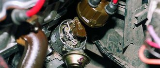
How to check the ignition coil?
The ignition coil consists of two electric coils, which are controlled by the engine controller. It serves to convert low-voltage 12-volt voltage into high-voltage to produce a spark.
Typical unit malfunctions
The short circuit is a reliable unit with a long service life, but it can fail.
Signs of a short circuit fault:
- engine power decreases;
- failures at certain speeds;
- misfires;
- high fuel consumption;
- work with jerks at idle;
- coil overheating due to internal short circuit;
- The Check Engine light comes on.
Based on these signs, it is impossible to say for sure that the short circuit is faulty. Therefore, its diagnosis is necessary.
BB: professional replacement
If you have decided to contact the service for the process of replacing high-voltage wiring, then it is, of course, a good thing, but not worth the money that will be asked of you. They can also confuse your brain on the topic of how often high-voltage wires need to be changed, with the logic that it is better to take care of prevention in advance than to get stuck on the highway. You won’t get stuck on the highway, the contact is not a sensor, even the last one doesn’t die right away. Replacement will cost from 1000 rubles. The advantage of service in this case will be the fact that they will look at the candles for you. And they will definitely be cleaned (they tend to become oily, which negatively affects the throughput for pulses through high-voltage wires).
BB: what do they look like?
High-voltage wires VAZ 2114
Naturally, the technical conditions for the existence of working wires are the conditions of a permanent conductor. If we add here temperature changes and the imperfection of our world, we get the fact that the contact system fails within a certain period of time. And it comes with a frequency of 30,000 km.
This is a control figure that tells you when to change high-voltage wires. The fact is that over time, internal resistance begins to increase in them, preventing the impulse from passing as it should. In this case, you may notice the following behavior of the fourteenth:
- You want to press your sneakers to the floor, but the engine doesn’t respond
- The engine may simply stall
- At idle the engine troits
- It often happens that car owners themselves do not notice how high-voltage wires are pierced
Of course, this is not an indicator of a malfunction only in high-voltage equipment, but there is a high probability that it was they who flew. Surely, it is worth carrying out a test procedure for all contacts.
And the tester showed that the wires had a long life. Well, the high-voltage wires on the VAZ 2114 need to be replaced. The procedure, in principle, is not troublesome. If you were able to test them, then you can replace them. The main thing is to understand the order of connecting high-voltage wires.
The fourteenth is an improved version of the nine, it has higher ignition power. Therefore, contacts have been added to the four high-voltage wires for connection to the ignition terminal itself, through which a signal goes to the spark plugs; Also, in the fourteenth system there are contacts leading to the switch, as well as contacts for connecting the adsorber valve to the gasoline injection system control unit.
The procedure for connecting high-voltage wires to a VAZ 2114
The connection diagram for high-voltage wires is quite simple:
- Cylinder 1 clings to the lower left contact
- Cylinder 2 clings to the upper left contact
- Cylinder 3 clings to the upper right contact
- Cylinder 4 clings to the lower right contact
This is sometimes called module bay interface in schematics. Essentially, everything is correct. The main thing is to understand that all cylinders are counted from left to right, like any count adopted from the logic of writing from left to right: 1,2,3,4. And the connection is obtained according to the following scheme: 1,3,4,2. Many people sketch and write down how the contacts were before removal. But, if you look at the module itself, there are docking numbers there. It's impossible to make a mistake.
Installing an electronic BSZ instead of a contact one
Today it is very rare to find a “seven” with contact ignition. With the arrival on sale of switches, distributors and coils for electronic spark generation systems, owners of classics began to massively re-equip their cars.
What is included in the BSZ kit
The process of converting a contact system into an electronic one is quite simple, and also inexpensive. The cost of an electronic ignition kit for a VAZ 2107 is about 2,500 rubles. It includes:
- transistor switch type 3620.3734 with connector;
- coil 27.3705;
- contactless distributor type 38.3706;
- connecting wires.
In addition, you will need spark plugs (preferably new ones) with a gap of 0.7–0.8 mm and a set of high voltage wires. Coil type B-117A (used in a contactless system) is not suitable for electronic ignition. Its characteristics do not correspond to those of other equipment in the circuit.
Video: review of BSZ elements for “classics”
Required Tools
To complete the work you will need:
- 8, 10 and 13 mm wrenches;
- screwdriver with a Phillips blade;
- drill;
- spark plug key;
- 36 mm wrench or with a ratchet mechanism for turning the crankshaft;
- self-tapping screws;
- pliers.
- Disconnect the terminals from the battery. We remove the battery and put it aside.
- Remove the high voltage caps from the distributor cap and from the spark plugs.
- Using a special wrench, unscrew all the spark plugs. We screw new ones in their place.
- Using a drill, drill holes on the left mudguard or on the engine shield to mount the switch.
- We attach the switch to the car body using self-tapping screws.
- Remove the distributor cap.
- We rotate the crankshaft, placing a wrench on the nut securing its pulley, until the distributor runner is aimed at the spark plug of the first cylinder, and the mark on the pulley points to the middle ebb on the timing cover.
- Using a 13 mm wrench, loosen the distributor mounting nut.
- Remove the vacuum hose from the distributor and disconnect all wires.
- We remove the old distributor from its seat.
- Remove the cover from the new distributor.
- Trying it on in place of the old one, we rotate the slider by hand until it is directed towards the first cylinder.
- We install a new distributor, tighten the nut, but do not tighten it completely.
- We connect the wire connectors and the vacuum regulator hose to the new distributor.
- We dismantle the old ignition coil by unscrewing the nuts securing it with a 13 mm wrench. We disconnect all wires from it.
- We install the new coil in place.
- We connect the connector with the wiring harness to the switch.
- We clean the ends of the wires. We install the chain:
- We securely attach the black wire from the switch to ground using a self-tapping screw or screw;
- connect the red wire to terminal “K” on the coil. We also attach the brown wire from the tachometer here;
- connect the blue wire from the switch and the blue wire with a black stripe to the “+B” terminal on the coil.
- We install the distributor cover and secure it. We connect new high-voltage wires to the cover and spark plugs.
- Let's try to start the engine. If it works, then everything was done correctly. Otherwise, we check the ignition circuit and the reliability of the connection of its elements.
BB: replacement
We remind you once again that before making a replacement, the high-voltage wires on the VAZ 2114 are usually tested. This will help you avoid unnecessary expenses and make sure that they are faulty.
Before you begin removing high voltage contacts, do the following:
- The car must be with the ignition turned off
- Open the hood
- Carefully disconnect all contacts from the ignition coils and the engine itself (just in the place where the wires supply the impulse to the VAZ 2114 spark plugs).
By the way, despite the obvious malfunction of the high-voltage wiring, often the cause of poor performance is oxidation of the area where the ends of the wiring meet. For prevention, it is advisable to wipe everything with WD. Many people try to revive the state of their wiring in this way, but attempts, although they sometimes bring results, are futile. You will increase the service life of high-voltage equipment by just a little bit. They cannot be rehabilitated, only replaced with new ones.
Now we take the new wiring and put it in place with the same accuracy as before:
- We remember the diagram of the position of the wires or put it next to us
- Or you sketched how it was before your intervention, it doesn’t matter, the main thing is to follow the installation order in the way you need it!
Otherwise, you risk burning out the engine and spending money on almost a new car.
Buying new wires
In this section we will describe which high-voltage wires are best purchased for Kalina at a car dealership. Standard wires from universal parts from AvtoVAZ will cost approximately 500-600 rubles. Set includes 4 pieces. Components for Kalina from early years of production are cheaper - about 400 rubles. High-voltage wires Kalina 8 cells. 50-70 rubles cheaper. Wires from third-party manufacturers, including foreign ones, are available for sale. For example, wires of the “HUCO” brand are distinguished by an increased insulating layer and, accordingly, cost more - about a thousand rubles. A complete ignition wiring harness for a Kalina costs about five thousand rubles in online stores.
Among “Kalinovodov” “high-voltage” brands “SLON” are popular. These products are distinguished by their ductility, resistance to fractures and, in general, have a longer service life compared to factory components at a competitive price - about 700 rubles.
Checking the voltage at the terminal block of the wires
- Disconnect the block with wires from the ignition coil (on the H4M engine, to access the coils of cylinders 1 and 2, remove the intake pipe).
- Turn on the ignition and measure the voltage at terminal 3 of the wiring harness block (the numbering of the terminals is on the ignition coil).
- The voltage at the terminal must be at least 12 V. If it is less or absent, it means the battery is discharged, there is a fault in the power circuit, or the engine control unit (ECU) is faulty.
- Turn off the ignition.
How to check ignition coil resistance
- We set the switch on the multimeter to the 200 Ohm position and close the probes (the instrument error will be displayed on the screen, which will need to be subtracted from the readings during testing).
- We check the primary winding of the ignition coil by connecting the probes of the device to the contacts.
- The resistance between pins 1 and 3 should be close to zero (about 1 ohm).
- The resistance between pins 1-2 and 2-3 should be high (tend to infinity).
Before connecting high-voltage wires on Kalina purchased at a car dealership, you need to assess the current state of the car's wiring. For diagnostics, the car owner will need an analog or digital multimeter.
Before connecting the device, you need to inspect the wires for external defects. These include:
If no external damage is observed, you need to connect a multimeter. You need to check the resistance of the armor wire, so you need to switch the device to ohmmeter mode. After this, the armored wire is disconnected from the spark plug and ignition coil. The ends of the wire are connected to the contacts of the multimeter, after which the device will show the current resistance level.
Data on normal resistance values are applied to the insulating layer. For passenger cars, normal values are in the range of 4-10 kOhm. In this case, on one specific car, the data values for individual wires should not differ by more than 2.5-3 kOhm. If this threshold is exceeded, then there is a problem in the ignition system.
There are several ways to check the functionality of the wiring without using measuring instruments:
- Use of additional insulated wire. You need to strip both ends of the additional wire. Short one end to ground, and run the other bare end along the caps, joints and the entire contour of the wire being tested. If there is a defect, the tester wire will give a spark;
- You need to drive the car into an unlit box, open the hood, and start the engine. If there is a breakdown in the VP insulation, the damaged area will spark.
The easiest way is to take a working high-voltage wire and test it on each cylinder by elimination.
BB: professional replacement
If you have decided to contact the service for the process of replacing high-voltage wiring, then it is, of course, a good thing, but not worth the money that will be asked of you. They can also confuse your brain on the topic of how often high-voltage wires need to be changed, with the logic that it is better to take care of prevention in advance than to get stuck on the highway. You won’t get stuck on the highway, the contact is not a sensor, even the last one doesn’t die right away. Replacement will cost from 1000 rubles. The advantage of service in this case will be the fact that they will look at the candles for you. And they will definitely be cleaned (they tend to become oily, which negatively affects the throughput for pulses through high-voltage wires).
Features of connecting high-voltage wires to the VAZ 2114
High-voltage ignition wires of the VAZ 2114 are part of the ignition system, through which an electrical impulse is transmitted from the module to the spark plugs. When the current hits the spark plugs, the fuel mixture ignites in the combustion cylinders, which gives rise to a new stroke of the engine.
BB wires must be of high quality
The design of the GDP, unlike conventional wires, is quite complex. In addition to the conductive core (which is made of copper) and protective insulation, they have metal tips and plastic protective caps.
Signs of breakdown
A malfunction of the ignition coil, or rather the module, can be determined by several characteristic signs:
- When accelerating, the car seems to fall through, there is a sharp short-term loss of power;
- The overall engine power level drops;
- Unstable behavior of the car when idling;
- The engine is shaking, which indicates cylinder failure.
Before you begin repairing the module, make sure that the spark plugs on your VAZ 2114 do not need to be replaced. Perhaps they have lost their effectiveness, the contacts have become clogged, or simply the life cycle of this component has come to an end.
High-quality spark plugs for a VAZ 2114 car with an 8-valve injection engine are not expensive, so you will not experience serious financial losses. But the ignition system and engine will work more efficiently.
But if the problem is still in the module, it is recommended to check the contacts. Most often, the basis for failure of the ignition module is the lack of quality contact. Sometimes they oxidize, stick, and the mass breaks off. Even if a layer of dust appears on the cylinder, it can fail.
WHICH GDP IS BETTER TO CHOOSE?
When choosing a GDP, two key factors must be taken into account - their resistance and breakdown voltage. The lower the resistance, the better the electrical impulse will be transmitted, and the magnitude of the maximum breakdown voltage determines how resistant the high-voltage wires on the VAZ 2114 will be to breakdowns.
The resistance value of products from different manufacturers differs from each other. As an example, we give you the resistance of the most popular types of GDP:
| Manufacturer | Resistance on cylinder No. 1 (kOhm) | Resistance on cylinder No. 2 | Resistance on cylinder No. 3 | Resistance on cylinder No. 4 | Breakdown voltage (kV) |
| Tesla | 3.27 | 4.16 | 5.02 | 6.26 | 50 |
| Cezar | 3.1 | 3.53 | 4.23 | 5.34 | 50 |
| Finwhale | 1.95 | 2.18 | 2.6 | 3.42 | 50 |
| Ween | 6.17 | 6.57 | 7.52 | 9.89 | 35 |
| Slon | 4.24 | 4.74 | 5.19 | 7.6 | 50 |
The products of the Czech company Tesla receive the largest number of positive reviews from the owners of the fourteenth. Their wires have optimal resistance and high breakdown voltage, and at the same time they are truly made to last - they do not tan or crack.
The cost of the Tesla GDP set is about 500 rubles, Cezar – 450 rubles, Ween – 270 rubles, Finwhale – 600 rubles, Slon – 500 rubles.
CONNECTION FEATURES
The order of connecting high-voltage wires must be strictly sequential, since each cylinder of the engine corresponds to a specific socket on the ignition module. Considering that there is a numbering of the sockets on the ignition module body, the risk of confusing anything is minimal.
The procedure for connecting high-voltage wires of the VAZ 2114 injection type depends on the year of manufacture of your car. Fourteeners before 2004 had 4-pin ignition modules installed, and cars after 2004 had 3-pin coils.
The connection diagram for VAZ 2114 high-voltage wires to the ignition module (until 2004) is as follows:
Connection diagram for VAZ-2114 with ignition coils (after 2004):
In the pictures you can see the numbers of the landing slots. Each number must have a corresponding cylinder connected to it (cylinder numbering is counted from left to right).
To correctly install high-voltage wires on the VAZ 2114, follow the following algorithm of actions:
- Turn off the ignition. Open the hood and remove the power terminals from the battery;
- We remove the old GDPs from the mounting sockets on the module and cylinders;
- We remember the location of the high-voltage wires of the VAZ 2114 and connect new GDPs according to the diagram. Before replacing, it would not be amiss to draw this very diagram by hand on paper so as not to confuse anything;
- We connect power to the battery and, to check whether we did everything correctly, start the engine.
When installing the wiring, do not try to connect individual air intakes to each other with plastic clamps; to do this, you must use the comb holder that comes with them. A thin clamp can easily wear through the insulating coating. Also make sure that the GDP does not bend.
Connecting armored wires on VAZ 2115 and 2113 is carried out in a similar way.
Contactless ignition system VAZ 2115
Device Features
VAZ-2115 vehicles can use two types of ignition systems: contactless (only on carburetor engines) and an ignition system that is part of the electronic engine control system (fuel injection system). This chapter describes a non-contact ignition system, and another is described in a separate repair manual for an engine management system with multipoint fuel injection.
| Rice. 9.39. Connection diagram of the wiring harness of the contactless ignition system: 1 – spark plugs; 2 – ignition distributor sensor; 3 – ignition coil; 4 – switch; 5 – carburetor solenoid valve control unit; 6 – carburetor solenoid valve; 7 – carburetor limit switch; 8 – ignition switch; 9 – mounting block; 10 – speed sensor; 11 – electric motor of the engine cooling system fan; 12 – fan motor activation sensor; A – blocks for connection to the front wiring harness; B – scheme of conditional numbering of plugs in the blocks of the ignition sensor-distributor and speed sensor; B – to power supplies; G – to the instrument cluster (signal for tachometer); E – to the instrument cluster (signal for the speedometer) |
| Rice. 7.1. Electrical diagram of VAZ-2115-20 cars (left half): 1 – headlights; 2 – fog lights; 3 – air temperature sensor; 4 – electric motor of the engine cooling system fan; 5 – blocks connected to the wiring harness of the ignition system; 6 – engine compartment lamp switch; 7 – block for connection to a single-wire type audio signal; 8 – sound signal; 9 – washer fluid level sensor; 10 – front brake pad wear sensors; 11 – oil level sensor; 12 – generator; 13 – engine compartment lamp; 14 – coolant temperature indicator sensor; 15 – starter; 16 – battery; 17 – relay for turning on fog lights; 18 – coolant level sensor; 19 – brake fluid level sensor; 20 – reverse light switch; 21 – windshield wiper gearmotor; 22 – oil pressure warning lamp sensor; 23 – block for connecting to the rear window washer electric motor; 24 – electric motor for windshield washer; 25 – instrument cluster; 26 – mounting block. Conventional numbering of plugs in the blocks: A – block headlights; B – electric fuel pump block; C – blocks for the mounting block, ignition switch, windshield wiper gearmotor; D – interior lamp |
On
| Rice. 2.58. Limit dimensions when grinding valve chamfers: I – intake valve; II – exhaust valve |
To check the ignition timing on a car there is a scale 1 (see.
| Rice. 9.40. Marks for setting the ignition timing: 1 – ignition timing mark by 5°; 2 – ignition timing mark at 0°; 3 – TDC mark on the crankshaft pulley |
When running the engine on a stand, it is possible to set the ignition timing using marks on the crankshaft pulley and on the front cover of the camshaft drive (
| Rice. 9.9. Installation of the ignition distributor sensor. The arrow indicates the mounting protrusion on the housing of the auxiliary units |
For the convenience of adjusting the ignition timing, there are divisions and “+” and “–” signs on the flange of the ignition sensor-distributor, and on the housing of the auxiliary units there is an adjusting protrusion (see Fig.
| Rice. 9.41. Scheme for reading the characteristics of the ignition distributor sensor on a stand: 1 – switch; 2 – ignition distributor sensor; A – to the “+” terminal of the stand; B – to the “breaker” terminal of the stand |
Removing characteristics of automatic ignition timing. Install the ignition distributor sensor on the stand, connect its terminals to terminals “3”, “5” and “6” of switch 1 (
| Rice. 9.42. Characteristics of the centrifugal regulator of the ignition sensor-distributor: A – ignition timing angle, degrees; n – rotation speed of the sensor roller – ignition distributor, min-1 |
Increasing the rotation speed stepwise by 200–300 min-1, determine from the disk the number of degrees of ignition timing corresponding to the rotation speed of the ignition distributor shaft. Compare the obtained characteristic of the centrifugal ignition timing regulator with the characteristic on
| Rice. 9.43. Characteristics of the vacuum regulator of the ignition sensor-distributor: A – ignition timing angle, degrees; P – vacuum, hPa (mm Hg) |
Smoothly increasing the vacuum, every 26.7 hPa (20 mmHg) note the number of degrees of ignition timing relative to the initial value. Compare the resulting characteristic with the characteristic on
| Rice. 9.44. Scheme for checking the non-contact sensor on the removed ignition sensor-distributor: 1 – ignition sensor-distributor; 2 – 2 kOhm resistor; 3 – voltmeter with a scale limit of at least 15 V and internal resistance of at least 100 kOhm; 4 – view of the plug connector of the ignition distributor sensor |
With the ignition distributor sensor removed from the engine, the sensor can be checked according to the diagram shown on
| Rice. 9.45. Scheme for checking a contactless sensor on a car: 1 – ignition sensor-distributor; 2 – adapter connector with a voltmeter having a scale limit of at least 15 V and an internal resistance of at least 100 kOhm; 3 – view of the plug connector of the ignition sensor-distributor |
On a car, the sensor can be checked according to the diagram shown on
| Rice. 9.46. Circuit for checking the switch: 1 – arrester; 2 – ignition coil; 3 – switch; 4 – resistor 0.01 Ohm ±1%, not less than 20 W; A – to the square pulse generator; B – to the oscilloscope |
The switch is checked using an oscilloscope and a square pulse generator according to the diagram shown in
| Rice. 9.47. The shape of the pulses on the oscilloscope screen: I – switch pulses; II – generator pulses; A – current accumulation time; V – maximum current value |
Rectangular pulses simulating sensor pulses are supplied to terminals “3” and “6” of the switch. The pulse frequency is from 3.33 to 233 Hz, and the duty cycle (the ratio of the period to the pulse duration T/TI) is 3. The maximum voltage Umax is 10 V, and the minimum Umin is no more than 0.4 V (
| Rice. 2.58. Limit dimensions when grinding valve chamfers: I – intake valve; II – exhaust valve |
Remove the plug from the clutch housing inspection hatch. Rotating the crankshaft by the pulley mounting bolt, turn it until the mark on the flywheel aligns with the middle scale mark (see Fig.
| Rice. 9.9. Installation of the ignition distributor sensor. The arrow indicates the mounting protrusion on the housing of the auxiliary units |
Lubricate with engine oil and place the O-ring on the flange of the ignition distributor. Install the ignition distributor sensor on the auxiliary units housing in such a position that the middle division on the ignition sensor distributor flange is opposite the installation lug on the auxiliary units housing (see.
| Rice. 9.48. Parts of the ignition sensor-distributor: 1 – clutch; 2 – body; 3 – vacuum regulator; 4 – centrifugal regulator; 5 – contactless sensor; 6 – sensor support plate with bearing; 7 – holder of the front roller bearing; 8 – cover; 9 – rotor; 10 – protective screen; 11 – holder of the front roller bearing assembled with the sensor support plate; 12 – washer for fastening wires; 13 – driven plate of the centrifugal regulator with screen; 14 – roller with the drive plate of the centrifugal regulator; 15 – weights; 16 – oil seal |
– remove cover 8 (Fig. 9.48), rotor 9 and protective screen 10;
– disconnect the vacuum regulator rod 3 from the sensor support plate 6, unscrew the fastening screws and remove the vacuum regulator;
– unscrew the fastening screws and remove the support plate 6 assembled with the sensor 5 and holder 7;
– remove the spring from coupling 1, remove the pin and remove the coupling and adjusting washers from the shaft;
– remove the roller with the centrifugal regulator 4 and washers from the housing 2.
Assembly is carried out in the reverse order of disassembly. During assembly, it is necessary to ensure that the axial free play of the roller is no more than 0.35 mm by selecting adjusting washers.
Video about “Contactless ignition system” for VAZ 2115
Contactless ignition systems for VAZ 2101-2107: SONARIK or BSZ kit?
VAZ ignition system
Injector ignition coil in BSZ (From V. Sushilov)
HOW OFTEN SHOULD I CHANGE GDP?
According to the recommendations of Avto-VAZ, replacement of high-voltage wires of the VAZ 2114 should be done every 30 thousand kilometers. In practice, motorists rarely comply with these replacement deadlines, since if the wires do not have any mechanical damage, they can travel about 100-150 thousand km.
When the service life is exceeded, the internal resistance of the GDP increases, which negatively affects the transmission of the electrical impulse. This leads to problems with ignition and acceleration dynamics, since when the supply of current to the spark plugs is delayed, the normal engine operating cycle is disrupted.
Change the wires every 25-30 thousand km and everything will be fine
Briefly about the essence of how spark plugs work
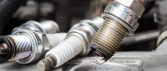
A spark plug is an ignition element designed to create a spark that ignites the combustible mixture under the cylinder piston . Their number is determined by the number of cylinders in the internal combustion engine block.
Spark plug
They are a nickel body with a ceramic insulator, inside of which there is a contact rod. Their synchronous operation is achieved by replacing the entire set, that is, 4 pieces. It is advisable that they be of the same brand and manufacturer.