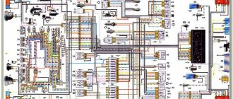
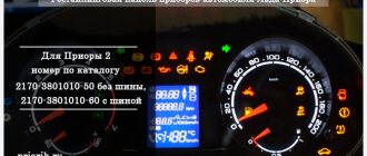
Assignment of contacts of the instrument cluster block
1 To the electric power steering 2 To the hazard warning lamp 3 To the emergency oil pressure sensor 4 To the parking brake switch 5 To the immobilizer control unit 6 To the airbag control unit 7 To the exterior lighting switch 8 To the turn signal switch (starboard side) 9 To the indicator switch turn (left side) 10 To the fuel injection system control unit 11 To the front passenger airbag deactivation sensor 12 To the seat belt sensor not fastened 13 To the control unit of the electronic brake force distributor 14 To the “RESET” button on the steering column switch (-) 15 To the level sensor brake fluid 16 To the anti-lock brake system control sensor 17 To the headlight high beam switch 18 To the instrument cluster lighting switch 19 Housing 20 To terminal “30” of the battery 21 To terminal “15” of the ignition switch 22 To the fuel consumption sensor 23 To the function switching mode key trip computer in a ring forward and changing the minutes (-) 24 To the mode key for switching the functions of the trip computer in a ring back and setting the clock (-) 25 To the outside temperature sensor (-) 26 To the outside temperature sensor (+) 27 To the fuel level sensor 28 To speed sensor 29 To coolant temperature sensor 30 Low-voltage tachometer input 31 Diagnostics during production of instrument cluster 32 To terminal “L” of generator relay regulator
Checking the vehicle speed sensor (VSA)
The easiest way to identify a malfunction of this element will be for owners of a Lada Priora with an on-board computer - a message will appear on the display stating that there are no signals to the speed sensor. Without the BC, you can also understand that malfunctions have appeared in the operation of the DSA: at idle, the power plant is unstable, engine thrust is reduced, the speedometer gives incorrect data, fuel consumption has increased. Now let's look at three verification methods.
Usually the test is carried out on a removed DSA; detailed instructions for dismantling this component are provided at the end of the article.
First method (without removal)
The Lada Priora must be raised so that only one wheel does not stand on the surface. The sensor contacts must be connected to a voltmeter. Now we move on to the raised wheel and begin to rotate it. If voltage and frequency appear on the tester, then the sensor is working.
Second method (with removal)
We dismantle the component we need. Using a voltmeter, you need to determine where the terminal that sends the signals is located. We connect its incoming contact to the meter, the second contact of the voltmeter must be grounded to the body of the Lada Priora or its engine.
Rotate the DSA, this way you can understand whether there are signals in the duty cycle. In this case, it is necessary to measure the output voltage. We put a piece of tube on the DSA axis; it must be twisted at a speed of approximately 4 km/h. As the rotation speed increases, the frequency and voltage readings on the meter display should increase.
List of elements of the electrical connection diagram of the rear wiring harness Lada Priora
1 – rear wiring harness block to the instrument panel wiring harness block; 2 – rear wiring harness block to additional wiring harness block 2 (left rear door); 3 – rear wiring harness block to side door wiring harness block (right front door); 4 – left side direction indicator; 5 – electrical package controller; 6 – right side direction indicator; 7 – interior lighting unit; 8 – handbrake warning lamp switch; 9 – left lamp; 10 – right lamp; 11 – interior air temperature sensor; 12 – interior lamp switch in the driver’s door pillar; 13 – switch for the interior lighting in the pillar of the right front door; 14 – switch for the interior lighting in the pillar of the right rear door; 15 – interior light switch in the left rear door pillar; 16 – block of the rear wiring harness to the block of the wiring harness of the side doors 2 (left front door); 17 – block of the rear wiring harness to the block of the additional wiring harness (right rear door); 18 – blocks of the rear wiring harness to the rear right loudspeaker; 19 – blocks of the rear wiring harness to the rear left loudspeaker; 20 – cigarette lighter; 21 – electric fuel pump module; 22, 23 – rear wiring harness blocks to instrument panel wiring harness blocks 2,3; 24 – trunk lighting; 25 – additional brake signal; 26 – trunk lock drive switch; 27 – interior lamp; 28 – rear wiring harness block to the front wiring harness block; 29 – left rear speed sensor; 30 – right rear speed sensor; 31 – sensor for automatic glass cleaning system (rain sensor); 32 – rain sensor sensitivity regulator; 33 – rear wiring harness block to instrument panel wiring harness block 4; 34 – block of the rear wiring harness to the block of the wiring harness of the parking system sensors; 35 – alarm unit for safe parking system; 36 – driver’s seat belt pretensioner; 37 – passenger seat belt pretensioner; 38 – rear wiring harness block to side door wiring harness block 3 (right front door); 39 – airbag control unit; 40 – parking system control unit; 41 – block of the rear wiring harness to the block of the rear additional wiring harness (tailgate); 42 – rear wiring harness block to rear additional wiring harness block 2 (tailgate); 43 – left seat heater; 44 – switch for electric seat heaters; 45 – right seat heater. 46 – rear wiring harness block to the parking system switch.
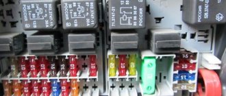
Fuses Lada Priora 21723
How to check the VAZ speed sensor
A failed speedometer sensor in a VAZ car is easily determined - in this case, the speedometer stops working, and it may also show some signs of life, but display incorrect information.
Using a tube, pliers or other available tools, rotate the sensor axis. In this case, you should see the voltmeter readings changing: the higher the speed, the higher the voltage (from 0.5 to 10 V). If this does not happen, the sensor requires replacement.
Fuse box of Lada Priora under the hood
F1 (green) 30 Electronic engine management system F2 (blue) 60 power package control unit, engine fan, heated rear window, ignition switch relief relay F3 (blue) 60 cooling fan power supply circuit, horn, alarm, ignition switch, combination devices, interior lighting, brake light, cigarette lighter F4 (blue) 60 Generator Priors F5 (red) 50 Electromechanical power steering F6 (blue) 60 Generator
Window lifter does not work - repair
If the window regulator on your car has stopped working, there could be many reasons for this. But, in general, all problems can be combined into two large groups: electrical failures and mechanical defects of the mechanism. In both cases, everything can be fixed with your own hands. In this article, we will analyze the main problems from both groups.
Lada Priora fuse box under the instrument panel
F1 25 Electric radiator fan of the cooling system F2 25 Heated rear window Priors F3 10 High beam right F4 10 High beam left F5 10 Sound signal F6 7.5 Low beam (left) F7 7.5 Low beam (right) F8 10 Alarm signal F9 25 Heater Priors F10) 7.5 Interior lighting, instrument cluster, brake light F11 20 Windshield wiper F12 10 Terminal 15 devices F13 15 Cigarette lighter F14 5 Left side light, license plate light, trunk light F15 5 Right side light F16 10 Terminal 15 ABS F17 10 Fog light (PTF) left F18 10 Fog light (PTF) right F19 15 Heated seats F31 or F27 30 Electrical package control unit
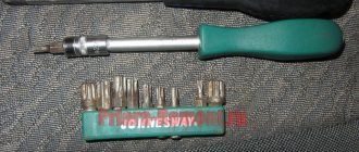
Replacement instructions
Tools for replacement will require a 10mm spanner and screwdrivers.
The replacement procedure consists of the following steps:
- Disconnect the negative from the battery.
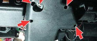
- We dismantle the air duct. To do this, unscrew the bolts on both sides.
- Now the speed sensor on the Priora has been found. We disconnect the connector with wires from it. Using a 10mm wrench, unscrew the fastening bolt.
- Then the DS needs to be pulled towards you. If it does not pull out, you can use a flat-head screwdriver.
- We remove the device from the gearbox housing.
- Next, install the new device and reassemble in reverse order.
Photo gallery “Procedure for replacing a DS on a Priora”
After replacement, you need to check the performance of the DS. To do this, start the car and drive a few meters, observing the instrument readings. The odometer and speedometer should show correct values.
Dashboard diagram Lada 2170
1, 2, 3, – instrument panel harness connectors to the front harness 4 – instrument panel harness connector to the rear harness 5 – contacts of the mounting block connector 6 – brake light switch 7 – instrument cluster 8 – lighting control module 9 – driver airbag module 10 – sound signal switch 11 – diagnostic block 12 – on-board computer mode switch 13 – ignition switch 14, 15 – blocks to the electric amplifier control unit 16 – electrical package controller 17 – light alarm switch 18 – windshield wiper switch 19 – air flow distribution gearmotor 20 – block heater control 21 – heater electric motor switch 22 – rear window heating switch 23 – clock 24, 25 – instrument panel harness connectors to the radio 26 – hazard warning switch 27 – glove compartment lighting switch 28 – glove compartment lighting switch 29 – instrument panel harness connector to ignition system harness 30 – airbag system control unit
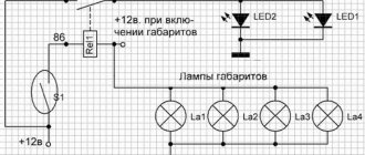
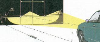
parking lights
For example, the electrical circuit of a Lada Priora station wagon has the function of both automatic and manual activation of side lights. The activation itself occurs after turning the handle for the side lights and headlights on the dashboard. The contact is triggered and the lights turn on.
The circuit contains fuses that serve to protect against overvoltages and short circuits. Power is supplied to a lamp located on the dashboard. To adjust the brightness of the lights, a special regulator located on the lighting control module is used.
The headlight design of the Priora differs from other cars. The electrical circuit of the VAZ Priora contains a light sensor, as well as a lighting control unit. After turning on the ignition and the lighting control button, the electronic unit responsible for lighting control is activated.
Connection diagram of the front wiring harness in Lada 2170
1 – starter 2 – battery 3 – generator 4 – battery harness and starter and front harness connectors 5 – 7 – front instrument panel harness connector 8 – engine compartment lamp switch 9 – left headlight 10 – right headlight 11 – brake fluid level sensor 12 – sensor air temperature 13 – washer motor 14 – reverse light switch 15 – engine electric fan 16 – heater damper gear motor 17 – additional resistor 18 – windshield wiper motor 19 – main fuse block 20 – heater motor 21, 22 – sound signal
Replacement
- socket wrench 10;
- screwdriver with flat bit;
- screwdriver with a Phillips bit.
Work order
- Place the car on a level surface.
- Raise the hood, disconnect the “–” wire from the battery.
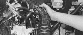
- Using a Phillips screwdriver, loosen the clamp securing the corrugation to the mass air flow sensor, disconnect the air duct, and move it to the side.
- Disconnect the power wires at the sensor connector.
- Using a 10 mm socket wrench, unscrew the nut on the sensor mounting stud.
- Pull it towards you; if this does not work, use a flat-head screwdriver to pry up the lower part of the sensor housing and remove it from the gearbox.
- Install a new sensor in its place, fix it and connect the wire block, having previously lubricated the rubber seal.
- Replace the air duct corrugation and secure it with a clamp.
- Connect ground to the battery.
Windscreen wipers
As for the windshield wipers of the Lada Priora, the electrical circuit in this case has a special programmable control unit. The circuit contains fuses to protect against overvoltages and short circuits.
The windshield wipers are turned on with a switch located near the steering wheel. The switch has eight positions, four of which are used to control the purifier. One position on the switch turns on the glass washer, the other two positions control the rear wiper. Another position is responsible for the disabled state of the windshield wiper.