Payment for goods and downloading of the book in electronic form (PDF format) is made on the website.
To do this, you need to find the book you are interested in and click on the “Buy” button. The price of the book is indicated on the button.
For convenience, the price on the website for residents of Russia, Belarus and Kazakhstan is presented in rubles.
For residents of Ukraine in hryvnias, and for all other countries - dollars.
After clicking on the “BUY” button, a payment window will open where you can select a payment system with which you can pay for the selected book using any bank card (Visa, MasterCard, MIR, etc.)
When you click on the “Pay by bank card” button, the Portmone payment system will open, which is the easiest way to make a payment.
In addition, the website offers four payment systems for payment:
- Yandex (payment from any bank cards, Yandex Money account, QIWI Wallet, terminals, etc.);
- Portmone (payment from any bank cards, Portmone account);
- PayPal (payment from any bank cards, PayPal account);
- WebMoney (payment from any bank cards, payment from WebMoney wallets).
Payment via Yandex Cashier
After selecting payment via Yandex, the Yandex Cashier payment system will launch, where you need to select a convenient payment method (bank card, QIWI, Yandex Money account, etc.)
After specifying payment details and confirming payment, payment for the goods will occur.
If you have a bank card in a currency other than the ruble, then the money will be debited from the card at the rate of the Central Bank of Russia at the time of the purchase.
This payment method is optimal for residents of Russia, Kazakhstan and Belarus.
Official website of the Yandex Kassa payment system https://kassa.yandex.ru
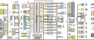
Light control module diagram (LCM) Kalina 2
| A1 - external lighting switch; A2 — rear fog lamp switch; A3 — control device for rear fog lights; A4 - front fog lamp switch; A5 - control device for front fog lights; A6 - device for turning on side lights; HL1, HL2 - LEDs for illuminating the pointer and outdoor lighting symbol; HL3 ... HLn - LEDs for illuminating symbols (symbols). | 1 + 12V. (Taken from the central unit, the signal for turning on the dimensions). 2 To the rear fog lights. 3 To the front fog lights. 4 To daytime running lights. 30 + 12V to generator terminal (30) 31 Housing. 56 To low beam headlight lamps. 58 To the side lights and the circuit of illumination sources. Xz To the ignition switch (+ 12V, terminal 15). |
Payment via Portmone
After selecting payment through Portmone, the payment system will launch, where you need to select the payment method: bank card or Portmone account.
The price in the Portmone payment system is converted into dollars at the exchange rate of the Central Bank of the country where you are located.
If you have a bank card in a currency other than the dollar, then the money will be debited from the card at the rate of the Central Bank of your country at the time of the purchase.
After specifying payment details and confirming payment, payment for the goods will occur.
Official website of the Portmone payment system https://www.portmone.com
Possible causes of fuel supply system failure
The fuel pump on Kalina is electric. The use of this design and operating principle is justified by a number of advantages. These are simplicity and reliability, compliance with the required characteristics in terms of fuel supply volumes and a high level of safety ensured by turning off the system when the engine stops running.
On the other hand, for high-quality work you need excellent gasoline and cooling of the fuel pump, and the process is also accompanied by an increased noise level.
- As a rule, poor quality gasoline and dirty filters lead to incorrect operation of the gasoline pump or its failure.
- If there is no response from the engine when you turn the ignition key, the problem may be due to a broken fuel pump.
- Since the main unit of the fuel system is powered by current, to troubleshoot it is necessary to check the electrical circuit going to the fuel pump.
Payment via PayPal
After selecting payment via PayPal, the PayPal payment system will launch, where you need to select the payment method: bank card or PayPal account.
If you already have a PayPal account, then you need to log into it and make a payment.
If you do not have a PayPal account and you want to pay using a bank card via PayPal, you need to click on the “Create an Account” button - shown with an arrow in the picture.
PayPal will then prompt you to select your country and provide your credit card information.
After specifying the information required to make the payment, you must click on the “Pay Now” button.
Official website of the PayPal payment system https://www.paypal.com
We activate the front PTF button in the MUS from normal.
We activate the front PTF button in the MUS from normal.
Schematic diagram of the ICC
This modification applies only to the new MUS model, with a vertical connector in a compact thin case.
First, open the ICC.
To remove the low beam and parking light switch, use a cloth or several layers of paper, placing them under the jaws of the pliers, apply a little force, and pull it.
Attention! The latches are filled with glue, carefully release the latches with a straight thin screwdriver or a utility knife
Be careful not to lose the plastic freewheel spring ends.
The ICC has been opened and the board has been removed.
photos of individual areas.
As you can see, the board does not have enough parts to use the PTF button function. Our task is to add them there.
To finalize, we will need to find a relay marked 21.3777MS, namely MS, from the manufacturer ABAR
Attention shortage! The main thing is to make sure that there is an 8-pin AS195 microcircuit on the relay board! datasheet
The main thing is to make sure that there is an 8-pin AS195 microcircuit on the relay board! datasheet
The housing and printed circuit board of the required relay looks something like this (the board is already without components).
If you have the opportunity to open the relay when purchasing, take advantage of it, so as not to buy the wrong relay.
Below are photos of relays that look the same but with a different filling, be careful, you don’t need to buy such relays!
If you find the required relay 21.3777MS (emergency), then solder it from its board to the MUS board:
- chip AS195 DA2A
— transistor BCP56-16 in VT2. - Zener diode BZX 79C 6V2RL in VS1.
SM4005 (1N4001-1N4007 or S1J) in VD6, VD7, VD8, VD9.
HL5 (PTF included, orange).
8.2 kOhm in R28, R24
510 Ohm in R27 910 Ohm in R4
- micro-relay from K1 to K1.
— solder two pins (male) of contacts 3 and 4 of the MUS (taken from the same relay).
— microswitch without fixation, socket SW2.
Photo of the original MUS deluxe board
photo of the upgraded board
my version with wall mounting
Now we need to modify the PTF power button in this way. We make a partition pusher and insert it into special grooves.
We take out the springs from disposable lighters, bite off the constrictions on them, and put them on the guide rods of the button.
We drill a 3mm hole in the button in the same place as on the adjacent one; there is a landmark on the back side.
Press the foil to the hole from the front side. Fill the drilled hole with hot glue, tear off the foil and get a well-filled hole through which the glow from the PTF indication LED will pass.
When assembling the MUS, it is necessary to install the contact group in this way:
To check the result of the modification, we need to apply power to it:
Minus on “31” contact +12V on 30 and Zx then turn the knob on the block to the mode of switching on the dimensions and then you can see what is happening on the diagram (on the MUS board).
If everything is soldered correctly and the parts are all in good condition, then when you press the PTF power button, the small relay on the MUS board should click, and +12 volts should appear on pin 4, close contacts 3 and 4, the indication LED should light up.
I express my deep gratitude to “Andrey710” for their help in the appearance of this article.
Payment via WebMoney
After selecting payment via WebMoney, the payment system will launch, where you need to select the payment method: bank card or WebMoney wallet.
If you already have a WebMoney wallet, then you need to log into it and make a payment.
If you do not have a WebMoney wallet and you want to pay in another way, you need to select any of the methods that WebMoney offers and make the payment
After specifying payment details and confirming payment, payment for the goods will occur.
Official website of the WebMoney payment system https://www.webmoney.ru/
Light control module diagram (LCM) Kalina 2
| A1 - external lighting switch; A2 — rear fog lamp switch; A3 — control device for rear fog lights; A4 - front fog lamp switch; A5 - control device for front fog lights; A6 - device for turning on side lights; HL1, HL2 - LEDs for illuminating the pointer and outdoor lighting symbol; HL3 ... HLn - LEDs for illuminating symbols (symbols). | 1 + 12V. (Taken from the central unit, the signal for turning on the dimensions). 2 To the rear fog lights. 3 To the front fog lights. 4 To daytime running lights. 30 + 12V to generator terminal (30) 31 Housing. 56 To low beam headlight lamps. 58 To the side lights and the circuit of illumination sources. Xz To the ignition switch (+ 12V, terminal 15). |
Downloading a book
After successfully completing the payment (by any method) and returning to the KrutilVertel store from the payment system website, you will be taken to the successful payment page:
On this page you need to indicate your e-mail, where access to download the book will be sent.
If you are already registered on our website, then simply follow the link to your personal account.
The book you purchased will be in your personal account, from where you can always download it.
Please note that after making the payment, you need to return back from the payment system website to the KrutilVertel website.
If for some reason you did not return back to the site and closed the payment system tab with a message about the successful completion of the payment, please let us know - we will send you a letter indicating access to download the book.
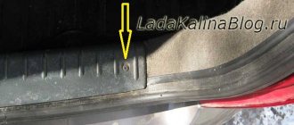
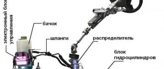
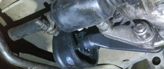
Fuse box
The weak link of the electric power steering on Kalina is the fuse box; if something doesn’t work, it’s worth checking them. To get to them, you need to open the dashboard, to the left of the steering wheel. To do this, pull the top part towards you and the latch will open.
Check if the fuse is working, if it fails, replace it. It is very easy to check, check the integrity of the thread inside the fuse. Changing a 50 amp relay to a 30 amp one will also help.
Newer versions of Kalina are equipped with electric amplifiers from Hyundai, which has a positive effect on its reliability. However, there are still thousands of cars with the domestic version, which malfunctions and breaks down from time to time. Now it will be easier for you to repair the electric power steering on Kalina yourself. The main thing to remember is that not every amplifier shutdown is a breakdown. And you can find the problem yourself and fix it, but somewhere you will have to go to a service center.
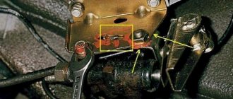
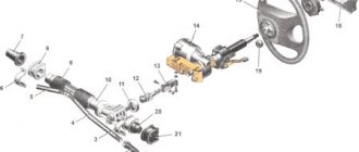
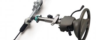
Electric power steering (EUR or EMURU) 11186-3450008 : 1 - steering shaft, 2 - electric motor, 3 - electronic control unit, 4 - torque sensor, 5 - rotor position sensor
In electromechanical power steering, the necessary compensation force is created by an electric motor. In general, the EUR consists of the following main components:
– steering shaft with torsion bar drive;
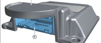
– electronic control unit (ECU);
– torque sensor;
– rotor position sensor.
The EUR is installed on the steering shaft, the parts of which are connected to each other by a torsion shaft with a torque sensor installed on it. When the steering wheel rotates, the torsion shaft twists, which is recorded by the torque sensor. Next, information from this sensor goes to the ECU, which calculates the required compensation force (taking into account the readings of the vehicle speed sensor) supplied to the steering shaft by the electric motor included in the ESD. In general, the EUR can be located both on the steering column and on the steering rack. In the latter case, the load on the steering shaft and its joints is reduced.
The advantages of the ESD relative to the power steering are the simplicity of the design and the compactness of the mechanism. In this case, the power steering is activated only when the steering wheel is rotated, while the power steering pump works constantly, creating additional load on the engine and, accordingly, increasing fuel consumption. The ESD is also flexible in configuration, allowing you to change the steering feel by changing the control program. The advantages of power steering include “honest” feedback and resistance to high loads, which allows it to be used on SUVs, trucks and other heavy equipment, while electric steering is usually installed on passenger cars.
Problems when paying with bank cards
Sometimes difficulties may arise when paying with Visa/MasterCard bank cards. The most common of them:
- There is a restriction on the card for paying for online purchases
- A plastic card is not intended for making payments online.
- The plastic card is not activated for making payments online.
- There are not enough funds on the plastic card.
In order to solve these problems, you need to call or write to the technical support of the bank where you are served. Bank specialists will help you resolve them and make payments.
That's basically it. The entire process of paying for a book in PDF format on car repair on our website takes 1-2 minutes.
If you still have any questions, you can ask them using the feedback form, or write us an email at [email protected] .
Error codes for EMURU "Lada Kalina"
So, we have studied the general circuit of the Lada Kalina electric power steering; now we will consider possible digital error codes and briefly describe their meaning. Note that equipment can be diagnosed using a DST-2M scanner with an installed VAZ-IZH cartridge or MT-10 software.
• C1000 – no error detected. • C1011 – no signal (engine speed circuit). • C1012 – no signal (speed sensor circuit). • C1013 – the voltage in the on-board network has dropped. • C1014 – the voltage at the ignition switch has dropped. Torque sensor: • C1021 – voltage (main output). • C1022 – voltage (control pin). • C1023 – incorrect output signal. • C1024 – no signal. Steering shaft position sensor: • C1031 – circuit malfunction (main signal). • C1032 – circuit malfunction (control signal). • C1033 – lack of power. Engine rotor position sensor: • C1041 – phase A circuit – malfunction. • C1042 – phase B circuit – malfunction. • C1043 – phase C circuit – malfunction. • C1044 – incorrect sequence. • C1045 – lack of power. Power circuits: • C1050 – short to ground. Motor, overcurrent: • C1051 – phase winding A. • C1052 – B. • C1053 – C. Broken phase windings: • C1054 – broken windings. • C1055 – winding A. • C1056 – B. • C1057 – C. Closing of phase windings: • C1058 – closing of windings. • S1059 – winding of phase A. • S1060 – B. • S1061 – C. • S1070 – unidentified. ECU - electronic control unit: • C1071 - RAM error. • C1072 – ROM error. • C1073 – EEPROM error. • C1074 – block relay. • C1075 – the radiator temperature is exceeded. • C1076 – ECU supply voltage. • C1077 – voltage for power capacitors. • C1078 – capacitor charging time. • C1079 – excess current in one of the windings. • C1080 – breakdown of the power transistor. Currently, DST-2M scanners are no longer produced; their place has been taken by more modern and advanced devices of the DST-12 model. With this equipment, you can diagnose not only faults in the Lada Kalina electric power steering. The DST-12 scanner is universal; it is used to service many cars - both those manufactured by AvtoVAZ and models from other manufacturers.
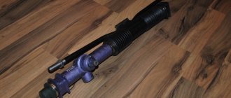
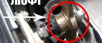
How to tighten the electric power steering rack?
The appearance of a knocking sound in the operation of the electric power steering is associated with the need to tighten the steering rack.
How to do it right:
Photo gallery “Adjusting the steering rack”
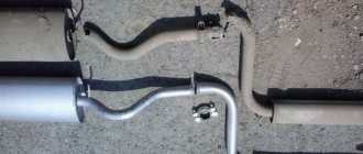
The module has been removed, what next?
Having disengaged the four latches, the module cover is disconnected from the “glass”. Then, the “glass” can be cleaned, the pump screen can be replaced, and so on. Details are illustrated in the photo:
The mesh will be fixed in front of the intake hole
The module is assembled in the reverse order. And when installing it in place, you need to make sure that the plastic protrusion coincides with the slot on the tank:
Here are a couple more tips:
- Do not turn on the pump motor “in the air” (the windings overheat);
- The module is replaced together with the sealing ring, which must be included in the kit.