November 28, 2014 Lada.Online 373 663 16
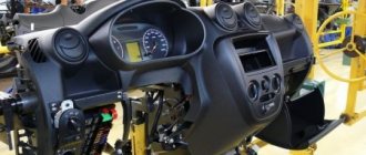
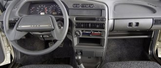
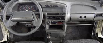
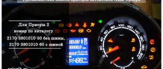
The combination of devices of Lada Granta and Lada Kalina 2nd generation is designed to display driving characteristics, the current state of vehicle systems that ensure traffic safety, as well as the correct operation of the entire vehicle as a whole. Next, we will consider a description of the Lada Granta dashboard, as well as the meaning of instruments and alarms.
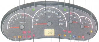
Description of the Lada Granta/Kalina 2 panel:
- tachometer , shows the speed of the engine crankshaft, the red scale zone indicates a dangerous operating mode for the engine;
- engine management system malfunction indicator (Check Engine) , turns on orange when the ignition is turned on and goes out after the engine starts, the lamp is lit after starting the engine or while driving indicates the failure of any element of the engine management system (does not mean that the engine should be stopped immediately, however, the cause should be eliminated as soon as possible), the error can be determined using the diagnostic connector;
- left turn signal indicator;
- emergency low oil pressure indicator , turns on in red when the ignition is turned on and goes out after starting the engine, the lamp is lit when the engine is running and a constant (for 5 s) buzzer signal indicates insufficient oil pressure in the system;
- ABS anti-lock braking system status indicator (optional) turns on orange when the ignition is turned on and after 2 seconds. after the engine starts, it goes out; in other cases, the lamp is lit, indicating a system malfunction that should be repaired at a specialized service station;
- immobilizer mode indicator lights up orange and displays the status of the immobilizer and the vehicle security mode;
- The coolant overheat indicator turns on in red when the ignition is turned on and after 5 seconds. after starting the engine it goes out, the sound signal indicates engine overheating (t>115C), the signal will be repeated until the temperature drops below 110C, when the indicator turns on, it is prohibited to operate the car, otherwise it will lead to serious engine damage;
- brake system emergency indicator , turns on red when the ignition is turned on and goes out after the engine is started, the lamp is lit and the buzzer signal (5 lights on) when the engine is running indicates a drop in the brake fluid level below the “MIN” mark in the master cylinder reservoir, operate the car with the light on indicator is prohibited;
- indicator for turning on the right turn signal (with a green filter in the form of an arrow);
- battery charging indicator , turns on in red when the ignition is turned on and goes out after the engine starts, the lamp is lit or glows half-lit while the engine is running indicates a lack of charging current due to a malfunction of the generator or voltage regulator, as well as low voltage (or breakage) of the belt generator drive, operating the vehicle with the indicator on is prohibited;
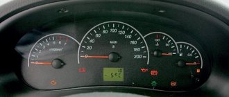
- speedometer , shows how fast the car is currently moving;
- indicator of the operating mode of the exchange rate stability system (ESC) (in a variant version), turns on yellow when the ignition is turned on and goes out after starting the engine, the lighting of the “ESC OFF” lamp indicates that the system is turned off, and lighting and flashing while driving indicates the activation of the exchange rate control system stability, in other cases the burning of the lamp indicates a system malfunction;
- signaling device prohibiting transition to higher gear “O/D OFF” (not used);
- headlight high beam indicator , indicates that the headlights are on high beam;
- signaling device for turning on the rear fog lights , indicates that the ZPTF is turned on;
- low beam headlight indicator , indicates that the headlights are low beam;
- indicator for turning on the front fog lights , indicates that the PTF is turned on;
- daily mileage counter reset button , by pressing the button, set the daily mileage counter in the liquid crystal display to 0 or select the daily or total mileage display modes;
- liquid crystal display of the on-board computer , displays information from the BC, see description below;
- door open indicator , lights up red if the door is open;
- reserve fuel indicator indicates the need to refuel the vehicle; do not allow the gasoline to run out completely, as this may damage the fuel pump;
- low tire pressure indicator , lights up when tire pressure drops;
- the electric power steering status indicator (connected in a variant), turns on in orange when the ignition is turned on and goes out after the engine is started; the lamp is lit while the engine is running indicates a malfunction of the power steering, which must be eliminated as soon as possible;
- driver's seat belt warning light , lights up when the ignition is turned on if the seat belt is not fastened;
- power unit fault indicator (not used);
- Airbag status indicator turns on in orange when the ignition is turned on and goes out after the engine starts; in other cases, the lamp is lit indicating a system malfunction; you must contact service as soon as possible, because In addition to failure in an emergency, the airbag may unexpectedly inflate.
Replacing LEDs
Having disassembled the instrument panel unit, you will notice that the illumination of two scales and the display is provided by flat LEDs. They, in turn, can be replaced with parts of the same standard size. But remember one rule: the switching polarity cannot be violated. On a planar diode, polarity is indicated by the presence of a “bevel” on one side.
There is an example when standard elements were replaced with blue light diodes:
Blue backlight of the display and two scales
Blue backlight of the standard display
The next video will show how you can further improve the tidy by simply replacing the LEDs.
The operating voltage of one diode is 3-3.5 Volts. Do not install elements designed for other voltages. It is not recommended to use LEDs that are too powerful and consume significant current.
conclusions
After reading the information given in the article, it will be easier for you to navigate behind the wheel and control the operation of the Lada Kalina car systems.
The instrument panel serves to inform the driver about all important processes occurring in his car. It is by using the scales, indicators, symbols and lamps located on this device that the person sitting behind the wheel is able to monitor the performance of components and systems. For the shield to function correctly as a single system, it requires regular diagnostics. It consists not only of scanning by connecting electronic reading devices to the computer, but also by visually monitoring the performance of all specified components of the dashboard (lamps, etc.).
So that the owner of the Lada Kalina, namely the instrument panel of this model we will talk about today, can easily navigate this complex device, the manufacturer kindly agreed to complete the car with the appropriate instructions. It is enough to familiarize yourself with its postulates and all the secrets of the dashboard will be revealed to you, then the instrument panel will not seem like something incredibly complicated.
The manufacturer did his best when developing the design of such a thing as the instrument panel on the Lada Kalina car. It is unlikely that you will be able to find owners dissatisfied with the “interface” of the device. The dashboard is painfully informative and primitive in terms of perceiving symbols and managing some of them.
Adding a digital scale
For those who have experience working with plastic, the following tuning option is recommended.
In the instrument panel, under any of the two scales, you can cut out a window in which a standard indicator is fixed. We are talking about a digital indicator consisting of two or three separate segments.
The plane of the tidy is cut through, an indicator is attached to the window
When the modification is completed, the dashboard looks like this:
3-segment indicator installed and secured
If there are glares, use a simple solution: cover the inside of the glass with a matte tint film. Good luck.
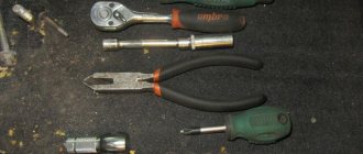
Operation algorithm
Started:
Note that the overlay is attached using iron buttons;
They are located on both sides of the emergency system key;
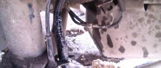
Let us note right away that it is easier to remove the panel through the passenger door. As for the method of draining the coolant and removing the stove, everything is done almost the same, except with some nuances. After the sound insulation has been carried out, we install the panel in place. Don't forget to first pass the block with wires for the switch. We also insert the glove compartment light in advance, using the appropriate holes. Thus, the operation can be considered complete. Having learned how to remove a torpedo on Kalina, you can safely take on this work, even without the help of an assistant. On the other hand, an extra pair of hands certainly won't hurt.
Installation of the dashboard Kalina 1
Installation is done in reverse order. For prevention, all surfaces are cleaned of dust and dirt, checked for defects and damage. The rag is dry; moisture may get on the surface of the electrical connector. Before installing a new instrument panel, check the correct location of the fastening units.
Installation steps:
- Install the plug connecting to the car's electrical network.
- Turn on the battery and check the operation of the dashboard.
- Disconnect the battery.
- Insert the lower rollers into the mounting recesses.
- Fix the shield, tighten 2 screws.
- Install the cover plate into the lower latches and screw in the mounting screws.
Several types of instrument panels have been developed for the Lada Kalina. They differ in appearance and functionality, but their installation diagram is the same.
When connecting the plug, you need to carefully move the latch to the “closed” position. This part is made of thin plastic and may break if pressed hard. First, insert the plug tightly, then turn the latch.
Correct installation of the Kalina 2 dashboard
Mount the instrument panel according to the standard scheme. First, clean the parts from dust and clogging. Check the integrity of the housing and replace the light bulbs if necessary. The temperature in the cabin should not fall below +15°C. In winter, it is recommended to carry out work in a heated garage or similar room.
Installation of the instrument panel:
- Connect the electrical connector and battery.
- Check the operation of the instrument module.
- Disconnect the battery.
- Screw the shield with 4 bolts.
- Install the decorative panel and secure it with 2 screws.
- Replace the protective plug or fuse box cover.
Rework by replacement
This option seems obvious: the speedometer and tachometer can be left in place, and the computer display can be replaced. In reality, such a replacement is difficult to perform. The on-board computer in Kalina-2 is integrated into the tidy circuit, so you cannot get rid of it. The instrument cluster unit is usually replaced as an assembly, and third-party companies have been able to provide several suitable solutions.
Tidying with a computer from a third-party company (option 1)
Tidying with a computer from a third-party company (option 2)
Tidying up the updated Priora, ITELMA
You can install a more “complicated” dashboard than in Kalina, produced by ITELMA. This company is a supplier of electronics for all VAZ cars. We will leave the choice to the owner. Happy tuning!
Removing the instrument panel on Lada Kalina 1
The first step is to disconnect the battery from the power supply system. Disconnect the negative terminal from the battery. If the temperature in the cabin is below +15°C, it needs to be warmed up to +20°C. The dashboard of Lada Kalina 1 is well illuminated by a flashlight, but additional light sources can be used.
The procedure for dismantling the shield:
- The steering column is installed in the lowest position.
- Removing the instrument cluster trim, unscrew the 2 screws at the top.
- Pull the cover towards you, overcoming the efforts of the two lower clamps.
- Use a Phillips screwdriver to unscrew the 2 screws located on the sides of the instrument panel.
- Move the top part of the shield towards you, tilting it.
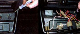
- Disconnect the connector with wires by turning the lock.
- Remove the instrument cluster from the recesses into which the structure's shafts are inserted.
Tip: the screws can fall behind the panel while unscrewing. It is recommended to use a screwdriver with a magnetic tip.
After this, the Lada Kalina 1 dashboard is repaired or replaced. You can replace the light bulbs by turning the desired socket counterclockwise.
The lighting devices are assembled with a socket, the power of each is 1.2 W. EEC designation W1,2W.
General diagram of electrical equipment of Kalina
On the electrical circuit of the Lada Kalina model, the pinout of connectors is carried out in several stages. According to the factory drawings, the general position of the elements is initially revealed, then each node is deciphered separately.
- Right front headlight assembly.
- Sensor indicating the position of the hood lock.
- Powering the horn.
- Starter terminal block.
- Battery power cables.
- Generator working unit.
- Voltage supply terminal for the wiper drive.
- Left head optics contact block.
- Right door lift chip.
- Likewise for the glass lift gearbox.
- Output to driver's door speaker.
- Driver's door lock drive.
- Windshield washer reservoir motor.
- Overboard temperature meter sensor output.
- Standard ECM connection connector.
- Same as 12 for the front passenger.
- Indicator of the remaining brake fluid in the expansion tank of the system.
- Same as 11 for the front passenger.
- The front passenger door power window switch, located in the driver's control unit.
- Driver's door window lift key.
- Lock button.
- Power supply for the lift gearbox for the front passenger door.
- Input of the mounting assembly.
- Anti-theft control unit.
- Likewise for signaling.
- Pinout on the dashboard.
- Right turn.
- Glove compartment lighting.
- Glove box light switch.
- Stop key switch.
- Anti-theft ignition switch terminal.
- Headlight design.
- Supply current to the steering column lever connector.
- Left turn signal.
- Right rear speaker block.
- Rear right door electric lock drive.
- Window window heating unit.
- Reverse blocking.
- Hazard breaker.
- Adjusting the stove fan.
- Auxiliary resistor for the stove.
- Stove motor.
- Power supply for rear left speaker.
- Rear left door lock terminal.
- Power supply for fuel pump and float.
- White reverse lamp switch.
- Stop button.
- Cigarette lighter power supply.
- ZX blocking – solenoid power supply.
- Chips for a tape recorder or speaker system.
- Illumination of used ventilation and stove.
- Supplying voltage and signals to the EUR.
- Interior lighting lamps.
- Rear right lampshade.
- Power to the trunk lid lock.
- Cargo compartment lighting drive.
- State license plate illumination.
- Auxiliary stop lamp.
- Directly heated windshield.
- Cargo compartment illumination lamp.
- Left stern light.
The following is the pinout of the first generation Kalina wires for each section individually. This was done due to the increased complexity of the main circuit, where all elements of the on-board circuits are indicated at once. An inexperienced user will not be able to navigate the generalized instructions.