Domestic cars are far from perfect. Therefore, many owners are constantly improving and modernizing their equipment. One of the elements of such improvements are the front panel buttons. Overexposure of the VAZ 2114 buttons allows you to change the color of their glow and transform the interior, making it more attractive and different from the standard one.
- Do-it-yourself overexposure of buttons on a VAZ 2114.
Which LEDs to buy and in what quantities? - How to remove buttons
- Replacing the backlight of the front panel buttons
Overexposure of old-style buttons
- Overexposure of new buttons
- Video: overexposure of VAZ 2114 buttons
- Video: refining the low beam switch button
Steering column switches from SHNIVA
Many people in the BZ have seen the replacement of the stock steering column switches with switches from SHNIVA.
Judging by the reviews, there were no people dissatisfied with the appearance, but regarding the convenience, opinions were divided into two camps: - those who think that reaching from the steering wheel to the switches has become far and inconvenient; — and those for whom the distance from the steering wheel to the switches is just right. I thought about all this for a long time, weighed the PROS and CONS, and yet curiosity got the better of me.
— Rotation switch 21230 — 1 piece (362 rubles)
— Windshield wiper switch 21230 — 1 piece (405 RUR)
The steering column switches from SHNIVA and the stock ones are interchangeable, so they do not require any modifications during installation. Their operating modes are completely the same.
To replace the steering column switches you must:
— Use a Phillips screwdriver to unscrew 3 screws and remove the upper half of the steering column casing (for ease of dismantling, the steering column can be lowered down);
— Squeezing the fastening tabs, remove the stock steering column switches from the steering column and disconnect them from the connectors; — Install the steering column switches from SHNIVA in the reverse order; — Reinstall the upper half of the steering column housing.
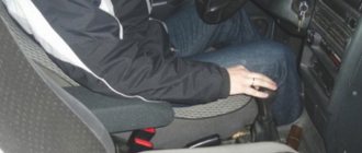
Many people in their comments ask how far the steering column switches have become from the steering wheel and ask for specific numbers. I specially measured the dimensions and am displaying them for your viewing.
Source
Checking and replacing steering column switches on a VAZ 2170 Priora
- Repair manuals
- Repair manual for VAZ 2170 (Priora) 2004+.
- Checking and replacing steering column switches
The steering column switch assembly consists of a connector secured with a clamp to the steering shaft bracket and two switches with levers.
The left switch turns on the turn signals and switches the headlights, the right switch controls the windshield washer and wiper, as well as the trip computer in the instrument cluster. The switches are secured in the connector with latches.
| . Positions of the steering column switch levers |
The positions of the switch levers are shown in, the contacts closed in this case are shown in table. 10.7.
Table 10.7 Contacts closed at different positions of the steering column switches
* Non-fixed lever positions.
Contact numbers of the turn signal and headlight switch
Wiper and washer switch contact numbers
You will need a tester.
1. Disconnect the wire from the negative terminal of the battery.
2. Remove the steering column casing (see “Removing and installing steering column casings” ).
3. Remove the steering wheel (see “Removing and installing the steering wheel” ).
| 4. Disconnect the connectors with wires from the left steering column switch... | 5. ...from the trip computer control block... |
| 6. ...and from the right steering column switch. | 7. Squeeze the plastic clips of the left steering column switch on both sides... |
| 8. ...and remove the switch from the connector. | 9. Similarly, remove the right steering column switch. |
10. To check the switches, connect a 12 V test lamp to the corresponding contacts indicated in the table. 10.7 (here is shown checking the inclusion of the left turn signal). Move the switch lever to the position corresponding to the contacts being tested - the lamp should light up. Otherwise the switch is faulty.
11. Install the steering column switches in the reverse order of removal.
↓ Comments ↓
1. Car structure
1.0 Car structure 1.1 General information about the car 1.2 Passport data 1.3 Car keys 1.4. Controls 1.5. Heating and ventilation of the cabin 1.6 Ensuring a comfortable air temperature in the cabin 1.7. Doors 1.8. Passive safety equipment on the car 1.9. Seats
2. Recommendations for use
2.0 Recommendations for use 2.1. Safety rules and recommendations 2.2 Running in the car 2.3 Operating the car during the warranty period 2.4. Preparing the car for departure
3. Problems along the way
3.0 Malfunctions along the way 3.1. The engine does not start 3.2 Malfunctions of the fuel injection system 3.3 Idle speed has disappeared 3.4. Interruptions in the operation of the 3.5 engine. The car moves jerkily 3.6 The car accelerates poorly 3.7 The engine stalled while driving 3.8. Oil pressure dropped to 3.9. Engine overheating 3.10. The battery does not recharge 3.13. Knocks in the engine 3.16. Wheel puncture
4. Maintenance
4.0 Maintenance 4.1. General provisions 4.2. Inspection work 4.3. Lubrication and filling works 4.4. Diagnostic work 4.5. Repair and adjustment work
5. Engine
5.0 Engine 5.1 Design features 5.2 Possible engine malfunctions, their causes and solutions 5.3 Useful tips 5.4 Checking compression in the cylinders 5.5 Removing and installing the decorative engine casing 5.6 Removing and installing the engine splash guard 5.7 Installing the piston of the first cylinder to the TDC position of the compression stroke 5.8 Replacing the drive belt gas distribution mechanism and tension roller 5.9 Replacing the power unit supports 5.11. Replacing engine seals 5.13. Engine cylinder head 5.15. Engine repair 5.16. Lubrication system 5.17. Cooling system 5.18. Power supply system 5.19. Design Features
6. Transmission
6.0 Transmission 6.1. Clutch 6.2. Gearbox 6.3. Front wheel drives
7. Chassis
7.0 Chassis 7.1. Front suspension 7.2. Rear suspension
8. Steering
8.0 Steering 8.1 Design features 8.2 Possible steering malfunctions, their causes and solutions 8.3. Steering column 8.4. Steering linkage 8.5. Steering gear
9. Brake system
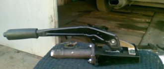
9.0 Brake system 9.1 Design features 9.2 Possible malfunctions of the brake system, their causes and solutions 9.3 Bleeding the brake system hydraulic drive 9.4 Removing and installing the vacuum brake booster 9.5 Replacing the brake pedal axle bushings 9.6. Main brake cylinder 9.7. Front wheel brakes 9.8. Braking mechanisms of the rear wheels 9.9. Pressure regulator 9.10. Brake hoses and tubes 9.11. Parking brake
10. Electrical equipment
10.0 Electrical equipment 10.1 Design features 10.2. Battery 10.3. Mounting block (relays and fuses) 10.4. Generator 10.5. Starter 10.6. Ignition switch (lock) 10.7. Electronic engine control system (ECM) 10.8. Ignition system 10.9. Lighting, light and sound signaling 10.10. Windshield cleaner 10.11. Washer reservoir 10.12. Electric fan of the engine cooling system 10.13. Electric motor of the heating and ventilation system fan 10.15. Cigarette lighter 10.16. Instrument cluster 10.18. Electronic anti-theft remote control system 10.19. Immobilizer 10.21. Replacing sensors and switches
11. Body
11.0 Body 11.1 Design features 11.2 Possible body malfunctions, their causes and solutions 11.3 Removing and installing windshield frame lining 11.4 Removing and installing soundproofing upholstery in the engine compartment 11.5. Removing and installing bumpers 11.6 Removing and installing the fender liner and protective wing cover 11.7 Removing and installing the front fender 11.8 Removing and installing decorative sill trims 11.9. Hood 11.10. Trunk lid 11.11. Doors 11.12. Seats 11.13. Seat belts 11.14. Rear view mirrors 11.15. Interior fittings 11.16. Instrument panel 11.17. Heater 11.20. Body care
12. Applications
12.0 Appendix 12.1 Appendix 1. Tightening torques of threaded connections, Nm 12.2 Appendix 2. Fuels, lubricants and operating fluids 12.3 Appendix 3. Nominal filling volumes 12.4 Appendix 4. Basic data for adjustments and monitoring 12.5 Appendix 5. Spark plugs used on vehicles 12.6 Appendix 6. Lamps used on a car 12.7 Appendix 7. What you need to have in a car 12.8 Appendix 8. Tools used when repairing a car
13. Electrical diagrams
13.0 Electrical Diagrams 13.1 Diagram 1. Instrument Panel Harness Connections 13.2 Diagram 2. Vehicle Front Wire Harness Connections 13.3 Diagram 3. Engine Electronic Control System (ECM) Harness Connections 13.4 Diagram 4. Vehicle Rear Wire Harness Connections 13.5 Diagram 5. Light Harness Connections license plate light 13.6 Diagram 6. Left front door wiring harness connections 13.7 Diagram 7. Right front door wiring harness connections 13.8 Diagram 8. Rear door wiring harness connections
Steering column switches. Part 1
Hi all. Today we’ll talk about steering column switches that are installed on front-wheel drive VAZs. Such switches are found on Samara and the Tenth model.
But these are already on Kalinas and Priors.
So, no matter what kind of car it is, be it a VAZ 2108 or a Priora, or maybe even a new Granta, there is one big problem that is very noticeable (this generally infuriates me). Tell me, do you like these holes (technological holes) between the steering wheel trim and the steering column switches?
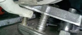
I don't like this either. But don’t be upset, today January 17, 2012 at 23:45 Moscow time, I found a solution to this problem. Comrades, pelvis manufacturers, let’s say a big thank you to the Ulyanovsk Automobile Plant, which makes the correct switches for the UAZ Patriot.
Pay attention to the installed rubber bands, these are exactly what are needed on the VAZ switches; moreover, the Patriot switches fit on the VAZ and are very convenient when installing a sports steering wheel.
Agree that it looks much more beautiful this way. Personally, I will be installing a detailed, photo report in the near future. Thank you for your attention.
Source
Why change the backlighting of individual buttons on the VAZ 2114 dashboard
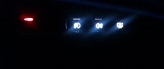
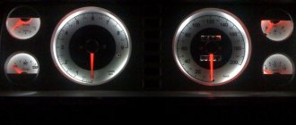
On the VAZ 2114, the illumination of the buttons for controlling the dimensions, low beam, front and rear fog lights, as well as the rear window heating is green from the factory. Over time, many owners get tired of this glow and there is a desire to replace it, make it non-standard. After making a decision about such modifications, you need to decide: do this work yourself or contact the service. Since the process of replacing button backlighting is not a complicated procedure, in most cases, car owners carry out such an upgrade with their own hands.
The standard green backlighting of the buttons gets boring over time.
#17: Steering column switches for Chevrolet Lacetti on VAZ 2113-15
Greetings to all!
The idea of implementing this idea has been in my head for a long time, but I never got around to it. The other day I went shopping, having found out the price for one switch (about 2500 rubles), at first I wanted to put this idea on the back burner, but I went to a local auto repair shop and bought the switches themselves from a Chevrolet Lacetti (hatchback) for a symbolic price: 1000 rub. for a couple of switches. Numbers for ordering steering column switches: Left switch 96392862 without fog light ring (hereinafter referred to as PTF) 96387324 with PTF ring Right 96552842 sedan with PTF without rear wiper with speed ring 96552852 sedan with PTF without rear wiper with speed ring 96552843 (96552851) hutchback under rear wiper with rear PTF and speed ring
Before purchasing, I surfed the site and found many ways of mounting, connecting, and everything in general. I racked my brains, but still did it my way.
So, the most important thing is to make a so-called adapter from the Chevrolet Lacetti switches to the VAZ switch block. I personally found two ways to do this:
- this is to use chips from the VAZ power window keys, and not modify them much;
- or just wires, I chose this method.
From the old wiring, I cut wires with so-called “folders”, approximately 8-10 cm long. From the other end of the wire I soldered small “female” pieces, suitable in size for the Lacetti switches.
The whole thing is heat-shrinkable, and now the adapter is ready.
Now about the connection.
Left switch Chevrolet Lacetti contacts Lacetti - contacts VAZ 2113-15
1 — 49al 2 — 49 3 — 49ar 4 — 56a 5 — 56b (not used) 6 — 56 7 — 30
Additional switch block Chevrolet Lacetti Next, we connect the light control
Right switch Chevrolet Lacetti contacts Lacetti - contacts VAZ 2113-15 ___|*|___ |1|2|_|3|4| |5|6|7|8|9|
4 — 53h 3 — HW 2 — 53ah 1 — W 9 — 53 8 — 53e 7 — J 6 — 53a 5 — 53b Additional switch block Chevrolet Lacetti
Now about fixing the switches themselves on the column. At work I found caprolon bushings.
We cut them in half using sandpaper or a file, cut off the excess and insert them into the slots where the latches are located on the original switches.
That's all, then we cut the steering column cover to fit the anthers, and enjoy! The drawing on the rear PTF on/off key has erased the acitonon, because In the future, there are plans to move this key to the front PTF key. As for the drawing on the near/dimensions key, I ordered a new one. The turn signals turn on/off very softly, my beloved wife appreciated it when traveling around the city. Pause in the first wiper mode from 2 to 15 seconds.
Source
Pinout of contacts and wires of steering column switches VAZ 2114
When diagnosing faults and repairing the electrical equipment of a VAZ 2114 (2113, 2115) car, quite often you have to deal with steering column switches since many electrical circuits of the on-board network are tied to them.
To quickly solve problems, you need to know exactly which and where the wire comes from to these switches, which contact is connected to them (pinout), as well as the switching (closing) of contacts when moving the levers.
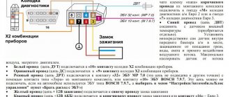
Here is a diagram where you can see it all.
Pinout of contacts and wires of VAZ 2114 steering column switches, diagram
Pinout of wires and switching of contacts of steering column switches of a VAZ 2114 (2113, 2115) car
Description of the scheme
Right steering column switch
53ah (yellow-blue wire) - plus (input) from the ignition switch (via fuse F7 in the mounting block and ignition relay).
53H (blue and white wire) - to the rear door window wiper motor.
WH (pink-black wire) - to the rear window washer solenoid valve.
W (pink wire) - to the windshield washer motor.
53b (gray-red wire) - to the windshield wiper motor, the second (high speed) wipers.
j (yellow-green wire) - on the windshield wiper relay “K3”.
53a (orange wire) - plus (input) from the ignition switch (via fuse F16).
53 (gray wire) - to the windshield wiper motor (first low speed or intermittent wiper mode).
53e (black and white wire) - intermittent positive with the windshield wiper relay.
Left steering column switch
49aR (two blue wires) - one to the starboard side indicators (via the mounting block), the other to the indicator lamp for turning on the turn signals in the instrument cluster.
49a (two blue-red wires) - one input (intermittent plus) from the turn signal breaker relay in the mounting block - “K2”, the other plus to the emergency light switch.
49aL (two blue-black wires) - one to the left side indicators (via the mounting block), the other to the indicator lamp for turning on the turn signals in the instrument cluster.
30 (pink wire) - plus (input) from the ignition switch.
56 (two green wires) - one positive from the exterior lighting switch, the other positive to the fog light switch in the rear lights.
56b (gray-red wire) - plus to the winding of the “K9” relay in the mounting block (low-beam headlight relay).
56a (blue-white wire) - plus to the winding of relay “K8” in the mounting block (relay for turning on the high beam headlights.)
Notes and additions
— On VAZ 2114 (2113, 2115) cars of different years of manufacture, the color of the wires may differ slightly.
Twokarburators VK - More information on the topic in our VKontakte group, on Facebook Twokarburators FB and on Odnoklassniki - Twokarburators OK
More articles on electrical equipment of VAZ 2114, 2113, 2115 cars
— Fog light in the rear lights of the VAZ 2114, connection diagram
— VAZ 2114 instrument brightness control, connection diagram
— How is the heater motor connected to the VAZ 2114, 2113, 2115?
— Pinout of the alarm system VAZ 2114 (2113, 2115)