The most important criteria for optimizing the performance of a diesel engine are the following:
- low toxicity of exhaust gases;
- low noise from the combustion process;
- low specific fuel consumption.
The moment in time at which the injection pump begins to supply fuel is called the beginning of supply (or closing of the channel). This time point is selected in accordance with the ignition delay period (or simply ignition delay). They are variable parameters that depend on the specific operating mode. The injection delay period is defined as the period between the start of injection and the start of injection, and the ignition delay period is defined as the period between the start of injection and the start of combustion. The start of injection is defined as the angle of rotation of the crankshaft in the TDC region at which the injector injects fuel into the combustion chamber.
Combustion onset is defined as the point at which the fuel-air mixture ignites, which can be influenced by the start of injection. For high-pressure fuel injection pumps, adjustment of the start of flow (closing of the channel) depending on the speed is best done using an injection advance device.
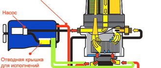
Purpose of the injection advance device
Because the injection advance device directly changes the injection start point, it can be defined as a feed start regulator. An eccentric type injection advance device (also called an injection advance clutch) converts the drive torque supplied to the injection pump, while at the same time carrying out its regulating functions. The torque required by the injection pump depends on the pump size, number of plunger pairs, quantity of fuel injected, injection pressure, plunger diameter and cam shape. The fact that drive torque has a direct influence on injection timing characteristics must be taken into account in the design along with the possible power delivery.
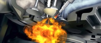
Ignition of diesel fuel.
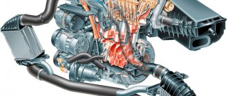
The piston compresses the air in the combustion chamber. The piston group allows you to create compression in the combustion chamber above 25 var. If this happens. The temperature of the compressed air rises to 700-900 degrees Celsius.
Heating the air in the combustion chamber
The air is heated. Because during compression the distances between air molecules decrease. Molecules are in constant motion. And the smaller the distance between them. the more often they collide with each other. As a result, a large amount of kinetic energy is released. Which turns into heat. The greater the pressure on the air, the smaller the distance between the molecules. The higher the temperature of the compressed air rises.
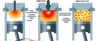
How does ignition occur?
The compressed air is heated to a temperature of 700-900 degrees. At the moment when the piston begins to approach top dead center. The injector injects fuel under pressure. The fuel is sprayed into small droplets. The movement of the drop begins to evaporate and a cloud of vapor forms around it. The ignition temperature of diesel fuel is 350 degrees Celsius. That is, at a compressed air temperature of even 500 degrees. Fuel vapors are guaranteed to spontaneously ignite. And they begin to expand from combustion. Pressure is created in the cylinder. By the time the piston approaches top dead center. The fuel will ignite completely and create maximum pressure in the combustion chamber. This pressure will do the engine work. As the piston moves away from top dead center, the fuel burns out. Thus creating additional pressure on the piston.
The quality of fuel combustion is largely determined by the pressure with which fuel is injected into the combustion chamber. The faster and more efficiently the fuel burns, the higher the pressure it creates. The higher the spray pressure in the nozzles. The smaller the droplets and the faster they move. Accordingly, they burn faster. Therefore, with the same volume of the combustion chamber, it is possible to achieve an increase in engine power by increasing the fuel injection pressure.
Design of the injection advance device
The injection advance device for an in-line injection pump is installed directly at the end of the injection pump cam shaft. The main differences between injection advance devices are open type and closed type.
The closed-type injection advance device has its own lubricating oil reservoir, which makes the device independent of the engine lubrication system. The open design is connected directly to the engine lubrication system. The body of the device is screwed to the gear, and the compensating and adjusting eccentrics are installed in the body so that they rotate freely. The compensating and adjusting eccentrics are guided by a pin, which is rigidly connected to the body. In addition to lower price, the “open” type has the advantage of requiring less space and lubricating more efficiently.
Operating principle of the injection advance device
The injection advance device is driven by a toothed gear, which is installed in the engine timing gear drive housing. The connection between the input and output for the drive (hub) is made through locking pairs of eccentric elements.
The largest of them, the adjusting eccentric elements (4), are located in holes in the locking disk (8), which, in turn, is bolted to the drive element (1). Compensating eccentric elements (5) are installed in the adjusting eccentric elements (4) and are guided by them and a bolt into the hubs (6). On the other hand, the hub bolt is directly connected to the hub (2). The weights (7) are connected to the adjusting eccentric element and are held in their original positions by springs with variable stiffness.
Rice. a) In the initial position; b) Low speed; c) Average speed; d) End position at high speed; a is the injection advance angle.
Adjusting the ignition of a diesel engine - instructions for the determined
The diesel engine can also be produced independently. First you need to lift the hood lid and fix it on the support post. At the top left of the rear of the engine, you need to find the flywheel (massive wheel), on the casing of which a mechanical device is located. The rod of this device must first be raised and rotated 90 degrees, then lowered into the slot located on the body.
Now remove the mudguard; to do this, use a 17 mm wrench to unscrew two bolts on the flywheel housing (it’s easier to get to this place from under the car). Insert a metal rod into the hole in the flywheel through the slot in the casing and turn the engine crankshaft. It must be directed from left to right until its movement is stopped by the locking rod at the top.
.
Now is the time to look at the fuel pump drive shaft; it is located on top of the cylinder block camber (the axis from which the cylinder banks diverge). If the installation scale of the drive coupling (flange that serves to transmit rotation from the drive shaft) of the high pressure fuel pump is turned upward, then in this case the mark on the fuel pump flange should be aligned with the zero mark of the drive and tighten the two mounting bolts. If the drive clutch setting scale is not turned up, then you will need to lift the stopper and turn the engine crankshaft one turn, and then all the above steps must be repeated in the same order.
Once the drive clutch bolts are tightened, you need to lift the flywheel stopper up, rotate it 90 degrees and lower it into the groove. On the bottom of the flywheel housing, you can return the dirt shield to its place (fastened with bolts). Now it’s time to close the car hood, the work is finished. All that remains is to start the car and check that the system operates correctly.
Injection pump size M
Rice. Injection pump size M
Rice. 1. Discharge valve; 2. Sleeve; 7. Cam shaft; 8. Cam.
The M-size injection pump is the smallest pump in the range of in-line injection pumps. It has a light alloy body and is mounted on the engine with a flange. Access to the inside of the pump is possible after removing the base plate and side cover, and therefore the M-size pump is defined as an open type injection pump. Peak injection pressure is limited to 400 bar.
After removing the side cover of the pump, the amount of fuel supplied to the plunger pairs can be adjusted and set at the same level. Individual adjustment is carried out by moving the clamping parts on the control rod (4).
During operation, the installation of the pump plungers and, together with them, the amount of supplied fuel is regulated by the control rod in the range determined by the design of the pump. The injection pump control rod of size M is a round steel rod with a plane on which clamping elements (5) with grooves are installed. The levers (3) are tightly connected to each control bushing, and a rod riveted to its end fits into the groove of the control rod clamping element. This design is known as linkage control.
The injection pump plungers are in direct contact with the roller pushers (6), and the preliminary stroke is adjusted by selecting rollers with the appropriate diameters for the pusher.
Lubrication of the M-size injection pump is carried out by normal oil supply from the engine. The M-size injection pump is available with 4.5 or 6 plunger pairs (4-, 5- or 6-cylinder injection pump) and is intended only for diesel fuel.
When it is necessary to adjust injection
At the factory there is a special machine for adjusting the injection pump. Therefore, it works well without adjustments. But, there are times when, after some repair work, you have to adjust the injection angle, for example:
- After replacing the timing belt
- You removed the fuel injection pump, and you cannot install its pulley according to the special marks.
- Any other unavoidable repair work that disrupts the injection angle adjustment.
Let me remind you, dear readers, that to fully adjust the fuel injection pump you need a special stand. Therefore, disassembling it into parts or turning all the screws on it is simply stupid. You will misadjust the device so much that later, without a stand, you will no longer be able to adjust the operation of the motor back. Therefore, if you don’t understand what and why to turn, do not touch the pump’s full load screw and other screws, because you will not be able to adjust them back. You don't need extra problems and expenses, do you?
Useful tips
The main recommendation before any work related to dismantling fuel equipment with your own hands is to apply and refresh marks on all gears, pulleys and other elements. Stripes are applied with paint or permanent marker. So that when assembling, combining them, it is easier to assemble the equipment and not disturb the ignition adjustment.
You can regulate the ignition on a diesel engine in the following ways:
- Adjustment by marks, if any.
- Selection of injection experimentally.
Injection pump size A
Rice. Injection pump size A
In-line injection pumps size A with a large flow range follow directly after the injection pump size M. This pump also has a light alloy body and can be connected to the engine by a flange or on a frame. Type A injection pump also has an “open” design, and the pump liners (2) are inserted directly from above into the aluminum housing, with the discharge valve (1) assembly pressed into the injection pump housing using a valve holder. The seal pressure, which is much greater than the hydraulic supply pressure, must be absorbed by the injection pump housing. For this reason, the peak injection pressure is limited to 600 bar.
Unlike type M injection pump, type A injection pump is equipped with an adjusting screw (with lock nut) (7) in each roller tappet (8) for setting the preliminary stroke.
To adjust the amount of fuel supplied using the control rack (4), the A-type injection pump, unlike the M-type injection pump, is equipped with gear control instead of a lever control. The toothed segment, clamped on the control sleeve (5) of the plunger, is in engagement with the control rack, and to adjust the plunger pairs to the same flow, the locking screws must be loosened and the control sleeve must be rotated relative to the gear segment and, thus, relative to the control rack.
All adjustment work on this type of fuel injection pump must be carried out on the pump mounted on a stand and with the casing open. Like the M injection pump, the A type injection pump has a spring-loaded side cover, which must be removed to gain access to the interior of the injection pump.
For lubrication, the injection pump is connected to the engine lubrication system. Type A injection pump is available in versions with a number of cylinders up to 12, and, unlike type M injection pump, it is suitable for operating on various types of fuels (and not just diesel).
Combustion of fuel in a diesel engine
Auto-ignition delay.
Fuel injected into the cylinder does not ignite immediately. First, its particles evaporate, mix with air and the mixture is heated to the auto-ignition temperature. This process is complex and multifaceted. Consequently, after the injection of fuel particles into the cylinder, an ignition delay occurs due to physical and chemical preparatory processes. The time elapsed from the moment particles enter the cylinder until combustion begins is called the self-ignition delay period.
The auto-ignition delay period is 0.001-0.005 s. If we assume that the engine operates at a rotation speed of 750 rpm, then its crankshaft rotates 1º in approximately 0.002 s, which means that during the self-ignition delay period the crank will rotate at an angle from 5 to 25º.
This circumstance forces fuel injection to be advanced, i.e. before the crank reaches TDC.
The angle at which the crank does not reach TDC at the start of fuel injection is called the fuel supply advance angle - this is the most important engine adjustment parameter for marine diesel engines; it is 15-33º.
The course of the combustion process.
d – fuel supply start point;
@0 – fuel supply advance angle;
@i – crankshaft rotation angle during the ignition delay period or ( ignition delay period ).
c – the point of combustion beginning during the ignition delay period (angle @i ) a certain amount of fuel entered the cylinder, usually 15-50% of the cyclic supply, i.e. from the dose injected per cycle.
The fuel ignites and therefore the temperature and pressure increase sharply ( cz ). The fuel entering the cylinder at the end of the delay burns quietly, ending up, so to speak, in a fiery environment.
At this time, the piston moves downwards, the volume above it increases and the pressure does not change significantly in the area ( z1, z ).
( z – z0 ) – the section shows the expansion process (the fuel burns out in this section).
The section ( сz´ ) is characterized by an intensive increase in pressure from Рс to Рz . If the rate of increase is more than 400-600 kPa/deg. P.K.V. ( 4-6 kgf/cm2 ), then the load on the piston will be shock, a knock will occur in the cylinder, such engine operation is called hard
.
Hard work is extremely harmful and affects bearing wear, causing deformation and breakage of piston rings.
The harshness of engine operation depends on the rate of pressure increase after auto-ignition, and this rate depends on the amount of fuel entering the cylinder during the auto-ignition delay period. In short , the harshness of diesel engine operation depends on the magnitude of the auto-ignition delay period: the longer it is, the harsher the diesel engine will operate.
This means that to ensure smooth operation of a diesel engine, one should strive to reduce the auto-ignition delay period ( adjustment - set the fuel supply advance angle earlier).
An increase in the temperature of the compressed air in the cylinder contributes to reducing the auto-ignition delay period. A cold diesel engine operates with “knocks” in the cylinder; after heating, the “knocks” disappear.
Soft engine operation is possible with good piston density in the cylinder, at a given compression ratio and while maintaining the engine in a warm - hot state.
Rough operation of a diesel engine is possible when the spray needle (nozzle) hangs - poor atomization quality.
The harshness of a diesel engine depends on the self-ignition of the fuel - this quality is characterized by the cetane number. It is determined by comparing the spontaneous ignition of the fuel under study and two reference hydrocarbons: the first has a minimal delay period for spontaneous ignition, the second is significant. (The comparison is made on a special single-cylinder engine with a variable compression ratio). First, determine the compression ratio at which the fuel under study spontaneously ignites when the piston is positioned strictly at TDC .
Then an equivalent mixture of cetane and alphamethylnaphthalene is selected, i.e. one that, at the same fuel supply advance angle and at the same compression ratio, self-ignites when the piston is in TDC .
The cetane number of fuel is the percentage of cetane in a mixture with alphamethylnaphthalene that is equivalent to the fuel in terms of flammability. If, for example, an equivalent mixture contains 45% cetane and 55% alphamethylnaphthalene , then the cetane number of the fuel will be 45 .
Quite smooth operation of high-speed diesel engines with a cetane number of 45 . low-speed ones can operate at a cetane number below 40 .
An increase in the cetane number above 55 causes a decrease in the completeness of fuel combustion. An excessive reduction in the auto-ignition delay period leads to a sluggish combustion process, which reduces efficiency .
Injection pump size WM
Rice. Injection pump size WM
The in-line injection pump size (type) MW was developed to meet the need for increased pressure. The MW injection pump is a closed-type in-line injection pump and its peak injection pressure is limited to 900 bar. It also has a light alloy body and is attached to the engine using a frame, flat base or flange.
The design of the MW injection pump is noticeably different from the design of the injection pump types A and M. The main difference is the use of a plunger pair, which includes a sleeve (3), a discharge valve and a discharge valve holder. It is assembled outside the engine and inserted from above into the fuel injection pump housing. On the MW fuel injection pump, the discharge valve holder is screwed directly into the sleeve, which protrudes upward. The preliminary stroke is adjusted using shims that are inserted between the body and the sleeve and valve assembly. Adjustment of the uniform supply of individual plunger pairs is carried out outside the injection pump by turning the plunger pairs. The mounting flanges of the plunger pairs (1) are equipped with grooves for this purpose.
Rice. 1. Mounting flange for the plunger pair; 2. Discharge valve; 3. Sleeve; 4. Plunger; 5. Control rack; 6. Control bushing; 7. Roller pusher; 8. Cam shaft; 9. Cam.
The position of the injection pump plunger remains unchanged when the sleeve assembly with the discharge valve (2) is turned. The MW injection pump is available in versions with up to 8 liners (8-cylinder) and is suitable for various mounting methods. It runs on diesel fuel and is lubricated through the engine lubrication system.