Fuel priming pumps serve:
- to overcome local hydraulic resistance along the path of fuel movement from the supply tank to the receiving cavity of the high-pressure pump: fuel purification filters, fuel lines, taps, turns and other devices;
- to overcome the difference in fuel levels in the supply tank and the receiving cavity of the high-pressure pump when the tank is located below the pump level;
- for reliable suction of fuel from the supply tank, which is often installed below the location of the high-pressure pump;
- to create excess pressure in the fuel supply line, which improves the filling of high-pressure pump sections and prevents the release of air bubbles and easily evaporating fractions from the fuel, which contribute to the formation of vapor-air cushions that turn off individual pumping elements;
- to create fuel circulation in the supply system, facilitating the entrainment of steam-air emissions into the fuel tank and improving the cooling of fuel system elements, especially injectors.
The minimum pressure in the fuel supply line, at which the system still operates, is 0.03-0.05 MPa. At this pressure, it is possible to supply fuel to the cavity of the high-pressure fuel pump by gravity. In the absence of discharge valves in high-pressure pumps, an increased pressure of 0.2-0.6 MPa should be maintained on the supply line. Currently, piston, rotary and gear pumps serve as booster pumps.
Rice. Diagram of a piston booster pump: 1 - roller, 2, 5, 9 - springs; 3 - undercut; 4 — inlet valve; 6 — channels; 7 - hand pump; 8 - plug, 10 - piston; 11 — discharge valve, 12 — channel, 13 — pusher
Low pressure fuel pump: design and principle of operation of the booster pump
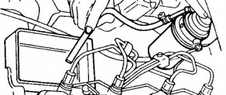
The diesel engine boost pump is a low pressure fuel pump (LPFP). The main task of this device is the function of supplying fuel to the high pressure fuel pump. As a rule, the booster pump is installed on the injection pump “box” or in close proximity to the high-pressure pump.
Both pumps are connected using fuel pipes, through which diesel fuel is supplied from the high-pressure pump to the high-pressure fuel pump. At the same time, diesel fuel is cleaned, which involves passing it through special coarse and fine fuel filters. Next, we will look at the device, as well as the principle of operation of the fuel booster pump in more detail.
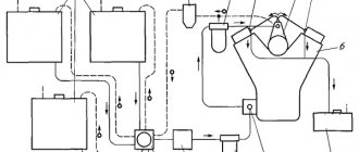
Power system diagram
The diesel engine power system diagram includes the main components, which include:
- Fuel tank;
- Fuel filters (coarse and fine);
- Fuel pump, booster;
- High pressure fuel pump (HPF);
- Injectors;
- Pipeline for pumping fuel under low pressure;
- High pressure pipeline;
- Air filter
The fuel system circuit has auxiliary components, which include electric pumps, exhaust parts, soot filters, mufflers, etc. The general design of the power system involves dividing fuel equipment into two groups:
- Fuel supply equipment;
- Air supply equipment.
The fuel equipment of diesel engines can have a different design; a split type system is by far the most common. This system is characterized by the separation of the fuel injection pump and injectors into separately functioning devices.
The fuel travels through high and low pressure overpasses. Checking the fuel supply hoses is a prerequisite for operating the power plant.
Storage, filtration and supply to the injection pump occurs at low pressure. After which, the fuel pump raises the pressure in the system for proper dosing and supply of a portion of fuel into the combustion chamber at the right time.
The diesel engine power supply system is served by two pumps:
- High pressure pump;
- Pump, fuel pumping.
The fuel pump supplies diesel fuel from the tank to the coarse and fine filters and then to the pump that creates high pressure. The liquid travels this path with a relatively low pressure.
Passing the injection pump, the fuel pressure is pumped to a high level. The operating order of the cylinders determines the supply of the working mixture. The pump that creates high pressure has several sections, each of which is responsible for a specific engine cylinder.
The power supply system of a two-stroke diesel engine may be of an undivided type. For such systems, a special device, a pump-injector, is used. This is a kind of combination of a fuel pump that creates high pressure and injectors into one device.
The design principle of operation of the diesel engine power supply system, which is most widespread, involves the location of injectors in the cylinder head. The main task of this arrangement is precise atomization of fuel in the combustion chamber. A large volume of diesel fuel is supplied to the fuel injection pump; its excess is discharged back to the gas tank through drain pipes.
Nozzles can be of two types:
- Closed type;
- Open type.
Closed type nozzles are more widely used. These injectors have a special shut-off needle that closes the fuel supply hole. Therefore, the injector cavity is connected to the combustion chamber only when the hole is opened and liquid is injected.
How to properly install a pump to increase water pressure
Connecting a circulation booster and preparing for operation more complex pumping devices equipped with a hydraulic accumulator are significantly different.
Connecting a circulating booster blower
Installation of a circulation unit to increase water pressure in a multi-story building is carried out in the following order:
- Using a grinder or a special device for plastic pipes, a piece of pipe corresponding to the installation size of the device is cut out on the inlet line;
- In accordance with the pipeline material, connecting fittings are installed. If metal pipes are used, either a welded connection or threaded fittings are used, if the pipes are plastic, a special soldering iron is used;
- Using the nuts included in the delivery set, the product is mounted into the main line.
Installing a suction pump module with a hydraulic accumulator is a much more labor-intensive process. To begin with, we list the main modules available in a typical pumping system:
- Self-priming module;
- Storage capacity;
- Automatic control system;
- Primary filter that prevents various abrasive fine pollutants from entering the system;
- Plumbing fittings, pipelines and flexible hoses.
To prevent the outflow of water from the pump housing when the power supply is turned off, it is possible to install a shut-off valve in front of the inlet pipe. In high-rise buildings, the supply main serves as a source of water; in the private sector, this is most often a private well or well.
Method of connecting an injection unit in the private sector
- The installation should be installed in close proximity to the water intake;
- The temperature at the installation site should not fall below +5 C;
- Contact of installation modules with walls is not allowed;
- The installation location must provide the possibility of maintenance and repair of the units.
There are several most common options for installing a pumping station with a hydraulic accumulator:
- Directly in the house;
- In the basement or ground floor;
- In the well;
- In a caisson;
- In a special insulated building.
Each of these options has its own advantages and disadvantages, so the choice of installation depends, first of all, on the layout of the site and the features of the building. After choosing the installation location, installation of the station begins, which consists of the following main steps:
Preparatory activities
which include:
a) Construction of a site for installation of equipment
. The foundation must be strong and provide reliable fastening of the device;
b) Digging trenches for laying pipelines
;
c)
Providing power supply
2. Installation of water intake system
. Depending on the modification of the pump used, there are:
a) Standard scheme
, with a surface pump unit and a built-in ejector. In this case, the design is a polypropylene pipe, with a check valve connected through a special coupling with a built-in coarse filter;
b) Using an external ejector
. With this design, a check valve with a coarse filter is installed on the inlet pipe of the ejector;
c) With submersible pump
, equipped with a mesh filter. In this case, it is enough to connect a non-return valve and a supply pipe.
3.
Installation of surface modules
.
At this stage, it should be remembered that the connection of each subsequent element should be made using ball valves and check valves. This design will provide the ability to service and repair individual pump modules without resorting to draining water from the entire pipeline;
4. Initial start-up of the station
is carried out after filling with water through a special neck located on the top panel of the working chamber.
https://youtube.com/watch?v=5c39kXyw3uM
Before starting any boost generator, you should make sure that grounding is present and in good working order!
What is a pressure boosting pump?
A booster electric pump is a unit with an electric motor and an impeller that pushes water into a pipe connected to it, resulting in an increase in pressure. Often the devices are installed at the inlet of household appliances: geysers, water heaters, automatic washing machines, dishwashers, high-tech Jacuzzis, the normal operation of which requires the supply of water with some pressure at the inlet.
Operating principle of a booster pump
Many booster pumps for water supply operate on a centrifugal principle with liquid moving by an impeller with blades mounted on an electric motor shaft. Water is supplied through a pipe located on the central axis of the shaft and is pushed out by the wheel blades through the side outlet.
Electric pumps that increase water pressure in a water supply system usually operate in an automatic on/off mode, controlled by a built-in reed switch flow switch. When not in operation, when there is no water flow in the pipeline, the unit is turned off; as soon as the tap is opened, water begins to move through the pipes, the relay is activated and the booster pump is turned on.
Many users and authors of Internet articles confuse a booster pump for water supply with a circulation pump installed in the heating systems of private houses. Although they structurally look almost identical and have a similar principle of operation, circulating types are designed for continuous supply of liquid to a height with constant maintenance of coolant pressure in the system and are turned off in two cases: when the thermal relay is triggered, indicating that the coolant temperature has been exceeded, and when the pressure switch is turned on ( rarely used), indicating too much pressure of the working fluid in the pipes.
Rice. 2 Cross-sectional view of a micro-rotor pump that increases pressure in a water supply system
Small-sized centrifugal booster electric pumps are manufactured using two technologies: with a wet and dry rotor. In dry-motor devices, the shaft of an electric motor with an impeller is separated from its rotor and stator winding by a highly hermetic torsional seal. This modification is characterized by a high efficiency of about 70%; usually an impeller is placed at the end of the housing to cool the engine. Dry-rotor modifications, compared to wet-rotor types, have larger overall dimensions, have higher power and performance, and are not critical to cleanliness and the absence of water due to the air cooling of the electric motor. But their main drawback is the high noise level, which significantly limits the scope of application in private water supply systems.
In versions with a wet rotor, the latter is separated from the magnetic core of the electric motor by a thin-walled glass in which it rotates, supported on end bearings. The glass and bearings are filled with water - this ensures silent operation and efficient water cooling. Thanks to this design, wet-rotor units have a low efficiency of about 40%, cannot operate in the absence of water cooling (they necessarily require winding protection against no-load), and have small overall dimensions. Their operation requires a clean environment, and the main advantage is quiet operation, which is often decisive when using them in individual water supply.
Rice. 3 Construction of a dry rotor unit
Related article:
Water pressure regulator in the water supply system - types and designs, installation . In a separate article we talk in detail about special pressure regulators that are installed in the water supply system, thus normalizing the water pressure. Read it, it might be interesting.
Vortex booster pumps
There are pumping modifications on the market that also use the vortex principle of operation; they are easily distinguishable by the suction and pressure pipes located on the same line on the side of the end part of the housing. Their impeller is made in the form of an impeller located on the electric motor shaft; water is sucked in through one of the side pipes and pushed out by the blades through the opposite outlet. To reduce hydraulic losses and increase efficiency, the gap between the blades of the vortex wheel and the walls of the working chamber is made minimal, therefore models of the vortex operating principle are much more demanding in terms of water purity than their centrifugal counterparts.
Advantages of installing a booster pump on a diesel engine
If we return to the main topic, the booster pump for a diesel engine is in many cases electric. Such a pump becomes an important element in the power supply system, as it allows not only to quickly and efficiently supply diesel fuel to the injection pump, but also to pass diesel fuel through filters.
This need can be dictated by various reasons, ranging from slight airing of the power system after parking and ending with the desire to make starting a diesel engine easier. The pump can be installed either in the fuel tank or integrated in certain sections of the diesel fuel supply lines after the tank.
As a rule, after installation, owners note that the diesel engine starts easier (you need to make fewer revolutions with the starter). There is also more stable operation of the internal combustion engine in different modes (transient modes, idle, operation under load). In some cases, an increase in power is also possible, since fuel is stably supplied to the injection pump even at high speeds.
When it is necessary to flush the diesel engine power system: main signs. How to flush the fuel system on a diesel engine, do-it-yourself flushing.
Design of a high-pressure diesel fuel pump, potential malfunctions, diagram and principle of operation using the example of a fuel supply system.
Design and operating diagram of the diesel engine power supply system. Features of fuel and its supply, main components of the power system, turbodiesel internal combustion engine.
What fuel injection systems are installed on diesel internal combustion engines. Diagram with mechanical injection pump, pump injector, Common Rail. Device, pros and cons.
Features of operation and causes of malfunctions of diesel injectors. How to independently remove, troubleshoot, disassemble and repair diesel engine injectors.
Types of diesel injectors in different high pressure fuel supply systems. Principle of operation, methods of controlling nozzles, design features.
Source
Fuel pump relay
The relay turns the fuel pump motor on and off. The fuel pump relay is controlled by the electronic control unit. The relay supplies voltage to the positive terminal of the fuel pump. The control unit turns on the relay by connecting the negative terminal of the relay control winding via a transistor to ground.
After turning on the ignition, the control unit activates the pump relay for two seconds. The pump relay also turns on when the engine starts. The pump remains on while the engine is running. The pump turns off after approximately two seconds if the engine stops turning or the engine does not start.
Let us remind you that the LCMS system has both training modules containing verification tests on the material itself (you can see them in the screenshots above) and special testing modules. This is what they are in relation to the topic “Fuel lift pump”.
The difference between training modules with built-in tests and directly testing modules is clearly shown in our material “Recommendations for developing your own content in LCMS ELECTUDE”.
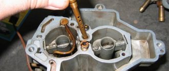
Disassembling the manual booster pump
Unscrew cover 2 (Fig. 142) from the cylinder body 3 and remove handle 1 with rod 4 and piston 6 from it. Knock out pin 5 and remove the piston from the rod. If necessary, remove gasket 8 from the cylinder and remove rubber ring 7 from the piston.
Specifications for Body and Piston
The outer diameter of the piston is 22 mm. The diameter of the housing bore for the piston is 22 mm. The normal gap between the piston and the housing bore should be in the range of 0.010...0.038 mm. Allowable gap 0.06 mm. The maximum gap is 0.1 mm.
Rod and Bushing Specifications
- The rod and bushing form a pair in which replacing one part with a part from another pair is not allowed.
- After washing in filtered diesel fuel, the pusher rod in the bushing should move freely by hand.
- Check the tightness of the pair by crimping under a pressure of 0.6...0.8 MPa (6...8 kgf/cm²) for 30...40 s. Fuel leakage is not allowed.
Technical requirements for the pusher assembly
- The roller should fit into the groove of the pusher with a gap of 0.2...0.5 mm and rotate easily on its axis.
- The pusher and piston must move freely, without jamming, in their seats under the force of the spring.
Valves and body. The contacting surfaces of the valves and the body must be smooth and mutually ground to a state that ensures tightness in the joints at a pressure of up to 0.2 MPa (2 kgf/cm²).
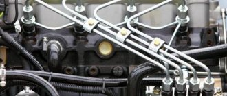
Fuel supply lines
The return line flows back into the tank along with air or steam bubbles. Air plugs that form on the inlet side of the injection pump are removed through bypass valve 6 with excess fuel flowing into the tank.
The fuel priming pump must be designed in such a way as to supply, along with the amount of fuel required for the injection pump, some excess amount for pumping and draining back into the tank.
The choice of fuel priming pump is determined by the following criteria: • injection pump type; • pumping power; • layout of fuel lines; • availability of free space in the engine compartment.
Design and principle of operation
The fuel priming pump takes fuel from the fuel tank and forces it under pressure through a fine filter into the suction cavity of the injection pump (under an excess pressure of 100...350 kPa or 1.0...3.5 bar). In most cases, mechanical piston pumps are used as booster pumps, which are attached to the injection pump (in rare cases, to the engine). The fuel priming pump is driven by a cam or ex-centric on the injection pump cam shaft or the engine camshaft. Depending on the required fuel consumption, single- or two-way fuel priming pumps are used.
Single stroke fuel priming pump
A single-stroke fuel priming pump (Fig. 3 and 4) is used for fuel injection pumps of models M, A, MW and P. The cam or eccentric 1 of the cam shaft (Fig. 3) drives the piston 5 of the pump through pusher 3. The reverse stroke of the piston is carried out under the action of the return spring 7. The fuel priming pump operates on the flow principle: when the cam is raised, the pusher moves down together with the pump piston, overcoming the resistance of the return spring. In this case, the inlet valve 8 located in the piston opens under the influence of the low pressure arising in the working chamber 4.
Rice. 3 a - stroke from the eccentric b - stroke from the spring 1. Eccentric 2. Injection pump camshaft 3. Pushrod 4. Working chamber 5. Pump piston 6. Inlet chamber 7. Return spring 8. Inlet valve 9. Bypass valve
Fuel flows into the working chamber through the open inlet valve of the fuel supply system. In this case, the bypass valve 9 remains closed. During the reverse stroke of the piston, the inlet valve closes and the bypass valve opens (Fig. 3b).
Two way fuel priming pump
Two-way fuel priming pumps (Fig. 5) with higher pumping power are used to work with injection pumps of models P and ZW, designed for a large number of engine cylinders and, accordingly, high fuel consumption. These pumps are also driven by a cam or eccentric on the injection pump cam shaft. In two-way pumps, fuel is pumped to the injection pump not only under the action of the pusher, but also when the piston returns to its original position under the action of the return spring, i.e., it is carried out twice for each revolution of the injection pump camshaft.
Rice. 4 1. O-ring 2. Spring plate 3. Pump body 4. Inlet valve 5. Pushrod bushing 6. Pushrod 7. O-ring 8. O-ring 9. Pump piston 10. Spacer washer 11. Line fitting to injection pump 12. Bypass valve 13. Return spring 14. Spring plate 15. Fuel supply line fitting
Rice. 5 a - stroke from the eccentric b - stroke from the spring 1. Injection pump cam shaft 2. Eccentric 3. Working chamber 4. Inlet chamber
Be sure to read: 10 reasons to choose a car with a diesel engine
Principle of operation
- When the booster pump is not working, the inlet and discharge valves are closed, and the above- and under-piston space is filled with fuel.
- When the cam shaft of the fuel pump rotates, the pusher and piston, under the action of the shaft eccentric and springs, perform a reciprocating movement.
- When the cam lobe moves away from the pushrod, the piston and tappet move under the action of the springs towards the cam shaft. In this case, pressure is created in the sub-piston space, and a vacuum is created in the space above the piston. The discharge valve closes, and the intake valve opens, and fuel from the intake port A enters the above-piston space, and from the sub-piston port it is squeezed out through channel B into the fuel filter and then into the head of the fuel pump.
- When the eccentric protrusion runs into the pusher, the latter, with the help of a rod, moves the piston, compressing the spring. Pressure is created in the space above the piston, and vacuum is created in the space below the piston. The intake valve closes and the discharge valve opens, allowing fuel to flow from above the piston to below the piston. Thus, fuel is supplied to the fuel pump when the piston moves towards the eccentric under the action of a spring, and when the piston moves under the action of the eccentric, it flows from the space above the piston to the space below the piston. During subsequent strokes of the piston, the process is repeated in the same sequence.
- When the pressure in discharge channel B increases (for example, when fuel consumption by the fuel pump decreases or the fuel filter is clogged), the spring, moving the piston, cannot overcome the resistance of the fuel, and the piston stops.
- The position of the piston in this case depends on the fuel consumption. The lower the fuel consumption, the higher the pressure in the discharge channel, the earlier the piston stops and the shorter its working stroke.
- With a smaller piston stroke, less fuel is supplied to the discharge channel. Therefore, even with low fuel consumption, the pressure in the discharge channel does not rise above a certain level.
- This automatically limits the maximum fuel pressure supplied by the booster pump to the system. This should be taken into account during operation.
- If the fine fuel filter is not replaced in a timely manner, its supply to the system becomes insufficient and the diesel engine loses power.
If the filter element becomes so clogged that its hydraulic resistance becomes greater than the spring force, the fuel supply will stop completely and the diesel engine will stop.
a — injection of fuel into the system; b - fuel flow; c — cessation of fuel supply; 15 - eccentric.
Gear pumps
Gear pumps are widely used in pumping systems for diesel engines for various purposes. The principle of operation and their devices are simple. The pump consists of driven and drive gears located in the housing. When the drive gear associated with the pump drive rotates, the fuel located between the teeth is transferred from the receiving cavity to the discharge cavity.
As a result of this transfer, a reduced pressure is created in the receiving cavity, and an increased pressure in the supply line.
To reduce the overall dimensions of a gear pump, the gearing between the teeth is sometimes made internal. The drive gear 2, located in the pump housing 1, engages with the sprocket 3, sitting on the axis 5. Between the sprocket and the teeth of the drive gear there is a crescent-shaped protrusion of the cover 4. The outer surface of this protrusion is concentric with the flange bore, and the inner surface is concentric with the sprocket. Therefore, fuel is supplied from the suction cavity to the discharge cavity, located both between the teeth of the sprocket and between the teeth of the drive gear. Gear pumps provide sufficient uniformity of supply and, as a result of high frequency pumping of small volumes of fuel, are reliable in operation. However, they cannot create the suction vacuum necessary to draw fuel from low-lying tanks.
Rice. Gear pump diagram: 1 - housing; 2 - drive gear, 3 - sprocket, 4 - cover, 5 - axle
Purpose of the diesel engine fuel priming pump.
1. The fuel priming pump is used to supply fuel from the fuel tank to the filter.
2. The fuel priming pump is used to supply fuel from the fuel tank through filters to the injectors.
3. The fuel priming pump is used to supply fuel from the fuel tank through filters to the high pressure pump.
Types of fuel priming pumps used on diesel engines YaMZ-236M and KamAZ-740.10.
1. The YaMZ-236M and KamAZ-740.10 diesel engines are equipped with piston-type fuel priming pumps.
2. Diaphragm-type fuel priming pumps are installed on YaMZ-236M and KamAZ-740.10 diesel engines.
3. The YaMZ-236M and KamAZ-740.10 diesel engines are equipped with piston and diaphragm type fuel pumps.
Design of a fuel priming pump for a diesel engine.
1. Driven half-clutch, weight axis, spring, drive half-clutch, housing, drive half-clutch pin, weight, spacer.
2. Pushrod, springs, cover, discharge valve, seat, sleeve, adjusting bolt.
3. Tappet rod, springs, tappet, exhaust valve, plugs, piston, inlet valve, pump housing, manual pump.
Operation of the fuel priming pump (manual pumping) of a diesel engine.
1. A rotating eccentric located on the cam shaft of the high-pressure pump runs against the pusher roller, as a result of which the spring is compressed and the rod with the piston moves, compressing the spring. Under the influence of fuel pressure in cavity A above the piston, the inlet valve is pressed against the seat, and the exhaust valve opens, fuel flows through the bypass channel into cavity B under the piston.
2. When the eccentric moves away from the pusher roller, the spring returns the pusher to its original position. At the same time, the spring, expanding, moves the piston in the opposite direction. A reduced pressure is created above the piston in cavity A, and an increased pressure is created under the piston in cavity B. The exhaust valve sits on the seat, and fuel from cavity B flows through the pump channels and pipeline to the fine filter. Due to a decrease in pressure above the piston, the inlet valve opens and fuel fills cavity A.
3. When the piston is moved upward by the handle, a vacuum is created in the cylinder, the inlet valve opens and fuel enters the cylinder. As the piston moves downward, pressure is created in the cylinder, the intake valve closes, and the exhaust valve opens and fuel is supplied to the fine filter.
Operation of the diesel engine fuel priming pump.
1. When the piston moves with the handle upward, a vacuum is created in the cylinder, the inlet valve opens and fuel enters the cylinder. As the piston moves downward, pressure is created in the cylinder, the intake valve closes, and the exhaust valve opens and fuel is supplied to the fine filter.
2. A rotating eccentric located on the cam shaft of the high-pressure pump runs against the pusher roller, as a result of which the spring is compressed and the rod with the piston moves, compressing the spring. Under the influence of fuel pressure in cavity A above the piston, the inlet valve is pressed against the seat, and the exhaust valve opens, fuel flows through the bypass channel into cavity B under the piston.
3. When the eccentric moves away from the pusher roller, the spring returns the pusher to its original position. At the same time, the spring, expanding, moves the piston in the opposite direction. A reduced pressure is created above the piston in cavity A, and an increased pressure is created under the piston in cavity B. The exhaust valve sits on the seat, and fuel from cavity B flows through the pump channels and pipeline to the fine filter. Due to a decrease in pressure above the piston, the inlet valve opens and fuel fills cavity A.
4. The operation of the fuel priming pump of a diesel engine is carried out according to the principles specified in answers 2 and 3.
Changing the performance of the fuel priming pump of a diesel engine.
1. The performance of the fuel priming pump of a diesel engine is changed by adjusting the stiffness of the piston spring.
2. The performance of the diesel engine fuel priming pump does not change.
3. When the engine fuel consumption decreases, the pressure in the cavity in front of the piston increases, and the force of the compressed spring is not enough to overcome the fuel back pressure. As a result, the active stroke of the piston is reduced, and accordingly, the fuel supply by the pump is reduced. The pusher moves freely in both directions. As the engine's fuel consumption increases, the pressure in the cavity in front of the piston decreases, the active stroke of the piston increases and the fuel supply by the pump increases.
How to choose a manual diesel fuel pump
On a diesel engine, when completing a fuel filter, two types of fuel pumping devices are mainly used.
The main difference is in the diameters of the fittings. Each of the configurations may be equipped with a water sensor, which is connected to the indicator. Equipment options vary depending on the region and the selected diesel engine. When a diesel engine is configured according to the first type, the return line is directed directly into the fuel tank. The valve's operation is configured automatically, so it either directs the return movement of fuel into the tank, or through the fuel filter into the high-pressure pump, using a small return circle.
Diesel fuel is kept at the constantly required temperature thanks to the automation of the valve. With such a natural movement of fuel, it is impossible to defrost the fuel filter, but it is possible to maintain optimal engine operation in severe frosts. Although if a malfunction occurs in the valve, this is problematic. Basically, such fuel filters are installed for vehicle operation in cold regions with low weather temperatures.
During the period of economic transformation of diesel cars, the pump was replaced with a button that was installed on the fuel filter cover. When you press the button, air is expelled from the system, and then fuel is filled. Then they made a kind of pear from rubber materials, embedded in the fuel line. In severe frosts, this device lost its elasticity and became hard, which made it impossible to pump fuel into the pump and directly into the propulsion system itself.
That is why, in the future, designers abandoned the use of an elastic bulb as a diesel pumping apparatus. Pear-shaped pumps made of elastic material with a straight or curved inlet are mainly used. In order to understand whether the valve is holding and whether it will allow air or fuel back in, you can try to blow it out; if it doesn’t blow in the opposite direction, it means it’s working.
https://youtube.com/watch?v=nMUj5SR9qso
The device of the booster pump and various types of low-pressure pumps
If we talk about design, the low pressure fuel pump has the following components:
- Drive shaft
- Rotor with blades
- Stator
- Distribution disk
- Drive gear regulator
- Couplings
The principle of operation is that the rotor begins to move first, as a result of which its blades move closer to the stator. As a result, under the influence of centrifugal force, “chambers” and a certain voltage are created. Then the fuel flows from the chambers to the fuel injection pump. To supply fuel, channels are made in the distribution disk. If the pressure exceeds the norm, part of the fuel is redirected to the pressure reducing valve.
Given that the booster pump and the high pressure pump are connected, a fuel drain choke is provided to maintain the required conditions. The specified throttle is a jet that is screwed into the injection pump.
This solution allows you to maintain the desired conditions in the chambers, while taking into account the dependence on the speed at which the drive shaft moves. This scheme is well suited for diesel engines, but there are other types of booster pumps.
Types of low pressure fuel pumps
Let's start with the fact that a low-pressure fuel pump is installed on any car, gasoline (carburetor, injector), and on many diesel ones, but not on all. This device “pulls” fuel from the fuel tank, after which the fuel passes through filters, enters the metering systems and is supplied to the engine.
In this case, booster pumps are mechanical and electric. On gasoline carburetor internal combustion engines there is a mechanical pump, on injection engines there is an electric fuel pump. However, if in gasoline analogues, regardless of the type of engine, such a pump is the main one, in diesel engines the booster pump supplies fuel to the injection pump.
A mechanical booster pump is usually installed on the cylinder block. This device is powered by the engine itself. Simply put, while the engine is rotating, a special cam of the pump is pressed, as a result the device begins to pump fuel into the carburetor. The mechanical pump also has a special lever, which allows you to manually pump gasoline before starting the engine.
An electric booster pump became a necessity after injection engines appeared. The fact is that for normal operation of the injector, fuel must be supplied to the injectors at a higher pressure compared to carburetor internal combustion engines.
Naturally, a mechanical pump with weak performance is not able to cope with such a task. It was replaced by an electric fuel pump. Such a pump is actually an electric motor and a pumping chamber, which are combined in a common housing. The supercharger is located directly in the gas tank and is immersed in fuel. Also integrated into the pump housing is a fuel level sensor and a special mesh filter for cleaning fuel.
This solution has a number of advantages, since the device is more productive and also does not overheat from excess heat in the engine compartment. Also, before starting the engine, there is no need to pump fuel manually, since after turning the ignition key, the booster pump immediately starts working, raising the pressure in the power system.
It should also be noted that in a circuit with an electric pump, fuel constantly moves through the lines, which allows maintaining a normal temperature of the fuel and avoiding overheating.
To eliminate air leaks, we recommend installing a booster pump
Operating principle
When the electric motor is connected to the supply voltage, the rotor and therefore the pump wheel rotates. As the pump wheel rotates, the pressure on the suction side of the pump element decreases. As the gasoline entering the pump approaches the pressure side, the free space decreases. As a result, gasoline under pressure is discharged from the discharge part of the pump element.
The internal cavity of the fuel pump is completely filled with gasoline under pressure. Liquid gasoline ensures good heat dissipation in the electric motor and eliminates the possibility of explosion due to sparking.
Application
The fuel priming pump is used in most cases when there is a significant distance between the fuel tank and the injection pump. Most often, the pump is attached to the injection pump housing. Depending on the layout of the engine in the engine compartment and the specific operating conditions, different layouts of fuel lines are required, especially to ensure fuel return. In Fig. 1 and 2 show two possible types of such schemes. If a fine fuel filter is located near the engine, the heat generated by the latter can lead to the formation of vapor locks inside the fuel line system. To prevent this, an excess amount of fuel is pumped through the intake cavity, thereby cooling the injection pump. With this connection scheme (Fig. 1), excess fuel enters the return line through bypass valve 6 and returns to tank 1.
Rice. 1 and 2 1. Fuel tank 2. Fuel priming pump 3. Two-stage fuel filter 4. In-line injection pump 5. Injector assembly 6. Bypass valve 7. Bypass throttle
Low pressure fuel supply system
One of the main characteristics of a diesel engine is the performance and pressure of both the mechanical part and the fuel equipment itself, which is very capricious and whimsical. To ensure the stability of these indicators and the durability of the equipment parts, we have to modify the fuel supply systems by installing additional accessories (filters, sedimentation tanks, heaters, booster pumps, etc.).
Based on this, the question arises: what exactly and in what sequence needs to be installed in order to obtain an optimal fuel supply system. Let’s not reinvent the wheel, but list in order what a low-pressure fuel system should consist of, from the tank to the fuel equipment (see figure):
Fig. 1 (1 - fuel tank, 2 - diesel fuel heater, 3 - coarse settling filter, 4 - fuel pump, 5 - pre-filter, 6 - fine filter, 7 - pressure-discharge indicator, 8 - transparent fuel line, 9 - engine).
- The fuel preheater
is designed to prevent paraffin from clogging the fuel filter in cold weather. - The coarse settling filter
cleans the fuel from water and large debris. Installed in front of manual and electric pumps, check valves. Prevents their premature wear and failure. - Fuel booster pump
with boost pressure 0.2 – 0.5 kg/cm². Pumps the system before starting, as well as after replacing the fuel filter. Eliminates airing of the system in case of minor leaks in the system. - The pre-filter
traps smaller dirt particles and water that have passed through the coarse filter. Prepares fuel for finer purification. Typically, the better the filtration rating of a filter, the more expensive it is. Thus, installing a pre-filter in the system allows not only to improve the fuel purification system, but also to extend the life of a more expensive fine filter. - Additional fuel heating
is installed when the fuel line is long and the power of one heater is not enough to combat paraffins. - The fine filter
finally cleans the fuel for supply to the fuel equipment (the degree of filtration is selected based on the design of the fuel equipment). - The pressure-discharge indicator
monitors the pressure at the inlet to the fuel equipment, which must be within acceptable limits. - A transparent fuel line
allows you to control the presence and amount of air entering the fuel equipment, which should be as small as possible.
So, now we know what should be on our car and in what sequence, which elements of the fuel supply system we already have installed, and which ones need to be added.
Now we list the main characteristics that you need to pay attention to when choosing additional accessories:
Bandwidth
It should be remembered that the installation of additional accessories, adapters, fittings, and fuel lines should not increase the resistance to the passage of fuel to the fuel equipment. Otherwise, at loads approaching the maximum, the engine will lack fuel with all the ensuing consequences and malfunctions of the fuel equipment.
To ensure that the resistance to the passage of fuel in the system does not increase, it is necessary that the throughput of the installed accessory is not less than the maximum performance of the fuel system where it is installed. As a rule, the throughput of a filter or pump is indicated in its technical characteristics. And the performance of the fuel system is easy to measure yourself.
To do this, simply lower the return hose from the fuel equipment into a measuring container, start the engine and let it run at 3000 rpm for at least 30 seconds. Then you need to recalculate the amount of fuel received in 30 seconds into liters per hour (l/h). The resulting value will be the performance of your fuel system.
Table 1 - Average performance of the most common fuel systems depending on their design and type.
| Type of fuel equipment | Productivity, l/h | Note |
| In-line injection pumps | 20-40 | Agricultural machinery, trucks, cars before 2000 |
| Single-plunger mechanical fuel injection pumps of distribution type. | 30-50 | All small and medium-duty vehicles up to 2000. |
| Distribution electromechanical injection pumps of distribution type | 40-60 | Passenger and medium-duty vehicles from 2000 to 2010. |
| Common Rail | 40-80 | Medium-tonnage equipment (from 1.5 to 4 liters) |
| Pump injectors | 40-80 | Found on Voltswagen cars |
When choosing an additional filter, you should also remember that as it gets dirty, the throughput of the filter element decreases. Therefore, it is better to choose a filter with a small performance margin. A correctly selected fuel filter should not create resistance in the fuel equipment even if it is 90% dirty. To our surprise, the announced performance of some brands of fuel filters does not correspond to even 60% of the declared one.
Maximum allowable pressure
Fuel pressure in different low pressure systems can vary from 0.45 kg/cm² to 6 kg/cm². On old (up to approximately 2005), as well as on some new designs of fuel systems, fuel priming pumps are located after the fuel filter and are designed for a maximum pressure of up to 1.5 kg/cm². This design is extremely unreliable due to the high probability of airing the fuel system at the slightest air leaks.
In modern cars, designers have corrected this shortcoming of the fuel system by installing a pump in the tank. The pressure in the fuel lines increased from 0.5 kg/cm² to 4–6 kg/cm². Based on this, new fuel system elements (filters, pumps, etc.) were developed to meet these requirements. Therefore, when modifying such a fuel system, you need to pay special attention to the maximum pressure value that the installed accessory can withstand.
The operating pressure of an accessory (filter, pump, etc.) can be found from its technical characteristics. In order to determine the pressure value in the fuel system of your car, you need to connect a pressure gauge to the line in front of the fuel filter, start the engine and take readings at idle and at 2500 rpm. The maximum value will be the pressure in your fuel system.
Filtration degree
Filtration degree
determines the maximum size of mechanical particles that can pass through the filter material.
Table 2 - Recommended filtration degree values for fine filters (final cleaning) depending on the type of fuel system.
| Degree of filtration, microns | Fuel system type |
| 2-5 | Common Rail |
| 5-7 | UIS pump nozzles, UPS pump sections |
| 10-20 | Distribution injection pumps |
| 20-30 | In-line injection pumps |
Table 3 - Recommended filtration degree values for pre-filters (coarse filters) depending on the type of fuel system.
| Degree of filtration, microns | Fuel system type |
| 20-30 | Common Rail, UIS pump injectors, UPS pump sections |
| 50 | Distribution injection pumps |
| 150 | In-line injection pumps |
And at the end of the article, we offer some tips that will help avoid problems with your fuel system:
- Monitor the performance of the fuel supply system components, especially such as fuel heating, contamination and water sensors, and a fuel filter contamination indicator.
- Try to use original spare parts or filters from trusted brands, such as Purflux, Mann, Champion, Stanadyne, Mahle, Knext, Fram, OE. Do not buy cheap filters from unknown manufacturers. Now there are about 30% of filters on the market in which the filter paper does not match the type of fuel equipment, and in some instances the filter paper is not glued at all.
- After replacing the filter element, cut and examine the used element. The condition of the filter media can tell you a lot. Perhaps it's time to wash the tank, or maybe your favorite gas station isn't as good as it used to be, and it's time to look for another one.
- Be selective when choosing a gas station. Always take a receipt after refueling. Do not refuel at suspicious or unbranded gas stations. After all, most of the breakdowns of fuel equipment occur precisely because of poor fuel quality. And if water is poured into your tank instead of fuel, then no filtration systems will help here. Therefore, it is so important to periodically check the water indicator for operation. If, after the next refueling, the indicator gives an emergency signal, then turn off the engine as quickly as possible and sort out the current situation. Drain the water from the filter (in most cases this is sufficient). If this does not help, then most likely water has entered the tank and it requires cleaning. To do this, drain the fuel from the tank, wash and dry it. After this, start the engine as quickly as possible so that the water that gets into the fuel equipment does not start “its rusty business.”
Unfortunately, among car enthusiasts who are beginning to be interested in upgrading their fuel system, there are many who have already experienced all the “delights” of expensive repairs. Therefore, do not repeat the mistakes of others and think about the filtration system in advance, so that it does not happen, as in the popular proverb: “Until the thunder strikes, a man will not cross himself.”
Article from the online store STO "Kovsh"
Operating principle of a manual booster pump
When you press the manual pumping lever, the membrane moves down through the drive, creating a vacuum in the cavity above it. Under the influence of vacuum, the suction valve opens and fuel enters the cavity, passing through a strainer above the membrane.
When the lever is released, the membrane rises upward under the action of a spring, compressing the portion of fuel. The created pressure closes the suction valve, simultaneously opening the discharge valve, and fuel rushes through the outlet fitting through the pipeline to the carburetor.
The operation of the fuel pump is similar when the engine is running, when the membrane is acted not by the manual pumping lever, but by the drive rod from the camshaft eccentric.
How does a hand pump work?
A hand pump is needed in a car to help the fuel pump, to improve the supply of fuel to the engine. When the mechanisms are idle for a long time, the manual diesel fuel pump fills the cavities with high pressure, which ensures an uninterrupted supply of fuel.
The vacuum created when the pump handle is raised opens the valve, sucking in fuel, the valve directs it to the piston. The increasing pressure during the return stroke closes the valve, and the fuel is directed to the filter thanks to the discharge valve. If it is particularly difficult to start the engine, it is necessary to check the presence of diesel fuel in the tank; for this, use a manual diesel fuel pump. This device is also used if air has entered the system and the fuel supply is interrupted, and so on until the air completely leaves the drain tube. Pumping stops after clean fuel without air starts flowing. If after this the engine operation does not improve and interruptions remain, you need to open the plug on the fuel pump to remove air and pump the entire system again using a manual diesel fuel pump.
The device is capable of dry suction; first it circulates air, then, using the already created vacuum, it pumps diesel into the engine. Only a low pressure pump can cope with such a task. Because using a high-pressure pump for such a problem is not only ineffective, but also useless. When air enters the engine, it will create a rapid supply of fuel. But such a circumstance will not solve the problem with the necessary preliminary pumping and removal of the air lock created in the engine.
Thus, the only correct solution would be to use a low-frequency manual diesel booster pump. On some diesel cars, the absence of a booster pump on the fuel line creates a certain vacuum, so air is sucked into the engine. Due to the vacuum and created leakage of diesel fuel, when the fuel filter is clogged or low-quality frozen fuel, this effect is enhanced.
This is interesting: DIY car rear view camera repair
On a diesel engine, when completing a fuel filter, two types of fuel pumping devices are mainly used. The main difference is in the diameters of the fittings. Each of the configurations may be equipped with a water sensor, which is connected to the indicator. Equipment options vary depending on the region and the selected diesel engine. When a diesel engine is configured according to the first type, the return line is directed directly into the fuel tank.
The valve's operation is configured automatically, so it either directs the return movement of fuel into the tank, or through the fuel filter into the high-pressure pump, using a small return circle.
Diesel fuel is kept at the constantly required temperature thanks to the automation of the valve. With such a natural movement of fuel, it is impossible to defrost the fuel filter, but it is possible to maintain optimal engine operation in severe frosts. Although if a malfunction occurs in the valve, this is problematic. Basically, such fuel filters are installed for vehicle operation in cold regions with low weather temperatures.
During the period of economic transformation of diesel cars, the pump was replaced with a button that was installed on the fuel filter cover. When you press the button, air is expelled from the system, and then fuel is filled. Then they made a kind of pear from rubber materials, embedded in the fuel line. In severe frosts, this device lost its elasticity and became hard, which made it impossible to pump fuel into the pump and directly into the propulsion system itself.
That is why, in the future, designers abandoned the use of an elastic bulb as a diesel pumping apparatus. Pear-shaped pumps made of elastic material with a straight or curved inlet are mainly used. In order to understand whether the valve is holding and whether it will allow air or fuel back in, you can try to blow it out; if it doesn’t blow in the opposite direction, it means it’s working.
This is interesting: Why the engine does not pull: reasons and diagnosis
Advantages of installing a booster pump on a diesel engine
If we return to the main topic, the booster pump for a diesel engine is in many cases electric. Such a pump becomes an important element in the power supply system, as it allows not only to quickly and efficiently supply diesel fuel to the injection pump, but also to pass diesel fuel through filters.
Also, the presence of a booster pump allows you to achieve stable operation of the diesel engine in all modes and at any speed, that is, there is no shortage of fuel under load. We also note that many owners of diesel cars that do not have an additional pump as standard decide to install it themselves.
This need can be dictated by various reasons, ranging from slight airing of the power system after parking and ending with the desire to make starting a diesel engine easier. The pump can be installed either in the fuel tank or integrated in certain sections of the diesel fuel supply lines after the tank.
As a rule, after installation, owners note that the diesel engine starts easier (you need to make fewer revolutions with the starter). There is also more stable operation of the internal combustion engine in different modes (transient modes, idle, operation under load). In some cases, an increase in power is also possible, since fuel is stably supplied to the injection pump even at high speeds.
- How to flush the fuel system of a diesel...
When it is necessary to flush the diesel engine power system: main signs. How to flush the fuel system on a diesel engine, do-it-yourself flushing. Read more
- Operating principle of the high pressure fuel pump
Design of a high-pressure diesel fuel pump, potential malfunctions, diagram and principle of operation using the example of a fuel supply system. Read more
- Diesel engine power system
Design and operating diagram of the diesel engine power supply system. Features of fuel and its supply, main components of the power system, turbodiesel internal combustion engine. Read more
- Diesel engine injection systems: types…
What fuel injection systems are installed on diesel internal combustion engines. Diagram with mechanical injection pump, pump injector, Common Rail. Device, pros and cons. Read more
- DIY diesel engine injector repair
Features of operation and causes of malfunctions of diesel injectors. How to independently remove, troubleshoot, disassemble and repair diesel engine injectors. Read more
- Diesel engine injector design
Types of diesel injectors in different high pressure fuel supply systems. Principle of operation, methods of controlling nozzles, design features. Read more
Selection and replacement of manual fuel pumps
Manual fuel priming pumps are operated in difficult conditions - fuel often freezes in them, they are exposed to high temperatures, aggressive liquids and gases. Therefore, some types of pumps (especially the simplest “pears”) quite often fail and require repair or replacement. Various signs may indicate the need for replacement: lack of fuel supply when the pump is running, visible fuel leaks and air leaks through cracks, lack of force on the body, button or lever during operation, creaks, clicks and other extraneous sounds, etc.
As a rule, when bulb pumps break down, they are simply replaced as an assembly - it is cheaper to install a new part than to repair the old one. A replacement hand pump should be of the same type and size that was previously installed on the vehicle. It is not recommended to use a smaller pump, since in this case you will have to spend too much time pumping fuel, and in some cases, a smaller pump will not be able to deliver fuel from the tank to the system at all (especially in the winter season).
Many diaphragm pumps can be repaired. For example, to restore the functionality of universal transfer pumps such as RNM-1KU2 and similar ones, repair kits containing a membrane, seals and other elements are sold. You can also repair fuel pumps with a combined drive used on cars with a carburetor engine.
To replace diaphragm and piston pumps, it is necessary to select units only of those models and types that are recommended by the vehicle manufacturer. Otherwise, the pump simply will not fit into place or will not work correctly.
Dismantling the old pump and installing a new one must be carried out strictly in accordance with the vehicle maintenance and repair instructions. If the work is done correctly, the pump will operate normally in any conditions, ensuring reliable engine starting.
Current types
A low-pressure fuel pump used in automotive internal combustion engine systems can exhibit different characteristics and design features at its output. All TNND can be divided into 2 main groups:
- mechanical;
- electric.
It is impossible to imagine a modern car, be it gasoline or diesel, without a fuel injection pump. After all, it is with the help of this device that fuel is pumped out of the tank and supplied for further operation of the internal combustion engine.
Let's look at mechanical devices first.
If we talk about the mechanical type, then such fuel injection pumps are mainly found on old carburetor engines. Mounted on the cylinder block, fixed with a simple screw connection. The work is performed by a crankshaft with an eccentric cam. When this cam is pressed, contractions occur and gasoline is pumped into the chamber.
To prevent fuel from pouring back into the tank, a special non-return valve is additionally used in this unit. Subsequent active presses contribute to the flow of fuel into the carburetor for subsequent combustion.
An electric type of device has become a more advanced and modern solution.
It is relevant for injection car engines, since the injector entails the use of a large number of various electrical equipment. As a result, it became impossible to pump fuel mechanically. He could not carry out his tasks and, accordingly, no longer created the necessary pressure, taking into account the requirements of the new system.
If we consider an electric pump in a simplified version, then it is the pump component itself and the electric drive (electric motor) enclosed in a housing. There is also a filter, a fuel intake and a flow sensor inside. The operating principle resembles a mechanical analogue. But the difference is that an electric motor is responsible for moving the fuel.
TNND are mounted inside the fuel tank. It is a mistake to think that this is wrong from a security standpoint. In the case of a mechanical type of device, heating of the fuel occurred under the influence of the operation of the internal combustion engine. In electrical systems, this problem is completely eliminated. The fuel continuously moves through a system of special tubes, which does not allow the working fluid to heat up to dangerous temperatures, or at least approach these values.
That is, we can safely say that installing a high pressure fuel pump in a gas tank is the most correct and rational solution from the standpoint of maintaining the optimal temperature. After all, the distance between the pump and the heat source is impressive.
It is also important to note that the electric pump design components are in constant contact with gasoline. They are immersed in it. As a result, it makes no sense to talk about any short circuits or ignitions.
In principle, they cannot happen
As a result, it makes no sense to talk about any short circuits or ignitions. In principle, they cannot happen.
Mechanical TNND
This system is installed directly on the cylinder block and secured with ordinary screws. The operation of such a pump is ensured using a crankshaft with an eccentric. When the eccentric cam is pressed, contractions are created internally. This is how fuel is supplied through the power system. To prevent fuel from getting back, the pump is equipped with a special valve. The remaining presses on the cam send gasoline to the carburetor. If a mechanical type fuel injection pump is installed in a car, then you can easily start the engine with it, even taking into account long periods of inactivity. To do this, simply manually pump the pumping mechanism.