How to check the distributor The answer is here
Distributors are so-called ignition distributors.
Used in ignition systems of carburetor internal combustion engines. Method 1
Instructions
1. To check the distributor, you need to place the car in the garage and close the doors. Turn on the engine and see if there are sparks.
2. When they are present, it means that in some place there has been a violation of the insulating layer. In daylight, the spark may not be visible.
3. The lid should not be damp and clean, because in some cases it may be burnt. By checking the connection of the wires, you can make sure that the contacts are intact or broken. As for the terminals in the cover, they should not be freely removed.
4. You should also check the rotor for burnout. It should be pumped. If there is no play, then there will be no gaps in the contacts.
Method 2
Instructions
1
To check the distributor, you should pay attention to the gaps and wear in the contacts. Approximate size - 1-3 mm
In the case where the contacts are burnt (flat), they need to be cleaned.
2. You can check the distributor by connecting a lamp to one of the side terminals of the distributor. Then turn on the ignition and crank the engine. In this case, the starting handle or pushing the machine (high gear) can help.
3. The lamp that lights up and goes out in this case should light up after an equal amount of time (four-cylinder engines - the lamp lights up and goes out every 0.5 revolutions). If this does not happen, it means that a short circuit occurs in some place, for example, the body touches the moving part of the contact.
4. If a capacitor is installed, if it malfunctions, a short circuit will also occur. When a person wants to check the distributor, if it is present and in working order, it can simply be turned off.
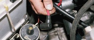
5. A quick way to check the distributor is to remove the wire from the spark plugs. Then you need to take the contact (5 mm gap), place it on the housing base and turn the motor. In this case, if the distributor is in good condition and normal operation, a spark will occur.
Purpose of the mechanism
Before we tell you how a faulty distributor should be checked to identify breakdowns, let’s look at the purpose of the device. The breaker is a unit designed to detect the moment of formation of high-voltage signals in the system. The distributor is installed on both carburetors and injectors, and this mechanism is used to distribute electric ignition among the engine cylinders. That is why many car owners are interested in the question of how to set the ignition and adjust the distributor, where to turn it - this is necessary for the normal operation of the power unit.
In its design, this mechanism differs from others in the presence of various elements in the structure, which tend to wear out over time. When the first signs of malfunctions in the operation of the distributor are identified, the device must be removed and repaired, since its condition largely determines the operation of the power unit and its characteristics.
In addition to setting the ignition, the distributor performs the following functions:
- interrupts the primary ignition circuit, which ensures the appearance of a high-voltage pulse;
- distributes the spark among the cylinder spark plugs in a certain sequence.
Breaker device design
Possible breaker failures and their symptoms
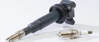
How to check the ignition coil
Repair of the distributor in the automotive industry is not carried out so often, which is due to the good reliability of this unit. Of course, there is no escape from breakdowns, but few people suffer from them. It is not so difficult to identify that it was the distributor that began to “pierce” the electric charge or grabbed another “sore”. The symptoms of malfunctions of the distributor-interrupter are specific and manifest themselves in the incorrect organization of the main functions of the device.
More precisely, possible replacement or adjustment of the distributor may be necessary if the following symptoms occur:
- the spark is gone;
- the ignition operation is upset;
- the battery stopped charging while the machine was running (not on all models);
- the car began to jerk while driving;
- Unburnt gasoline drips from the exhaust pipe.
As for specific faults, they are often represented by the following list:
- The distributor drive (rotor) has worn out or burned out. The malfunction is diagnosed through a detailed examination of the rotor and experimental verification of its correct operation. If an element breaks, it may be necessary to either install a new drive or completely replace the distributor;
- The network has broken through. This, by the way, can happen in any component of the distributor. Most often, the high-voltage wires that extend to the spark plugs from the distributor cover are affected. Other elements of the system (small wires, connectors of distributor parts, contacts, etc.) break down noticeably less often. Checking for this malfunction is carried out using a regular “ring”;
- The seals are worn out. Perhaps this is a rather rare breakdown with characteristic symptoms. To be more precise, we are talking about a general disorder of the ignition and untimely formation of a spark. For repairs, it is necessary to replace the distributor seals, and it is worth replacing not only faulty elements, but also those that work correctly, so to speak, for prevention;
- The distributor slider or the sensor responsible for distributing the charge between the spark plugs has broken. Characteristic signs of this breakdown are the inability to correctly configure the distributor or its complete failure to operate. The malfunction is eliminated by replacing the slider or sensor;
- The ignition coil has failed. This failure is characterized by either absent or incorrect sparking. Repair is carried out by replacing the burnt coil with a new one.
Other distributor malfunctions appear much less frequently. In any case, repairing this unit is not an easy task, so no motorist will be able to figure it out right away
To understand the whole essence of repairing a distributor, it is important to fully understand the principle of its operation and constantly practice. If you don’t want to learn all the basics of repair work, it’s better to entrust the repair to a professional who specializes in repairing car ignition systems
Why does the VAZ-2107 twitch - let’s understand the operation of the “distributor”
Well, if the engine of your VAZ-2107 suddenly stalls and does not start, we will find the reason and eliminate it quickly. Everyone knows that this happens if the “spark” disappears or there is no gasoline supplied at all. It’s much worse when the car seems to be moving, but the nerves are fraying - uneven idling, jerking and twitching when driving. Finding the root of the problem can take a lot of time and take a lot of money out of your pocket. And more often than not, these searches ultimately lead to a distributor. This material will help you correctly replace it with a working one, select a suitable replacement, and understand the device and operation.
Procedure for adjusting the gap
How to test a resistor for functionality with a multimeter
Remove the distributor cap and the slider and, slowly turning the engine crankshaft with the starting handle, set cam 4 to the position where the gap between the breaker contacts is greatest, i.e., when the breaker lever pad is installed on the top of the cam face. After this, use a flat feeler gauge to check the gap between the contacts. If the gap does not correspond to the value indicated above, it is necessary to loosen the locking screw and, by turning the eccentric 23, set the required gap; then tighten the screw and check the gap again. Then you need to put the cover in place and secure it with latches 10. After adjusting the gap between the breaker contacts, the correct setting of the ignition timing is disrupted. Therefore, the ignition installation must be checked and, if necessary, clarified.
Checking the ignition timing of the VAZ-2107 engine
The methods described below make it possible to independently adjust the ignition timing. They are suitable equally well for both contact and non-contact distributors. We adjust the ignition timing at idle speed . We warm up the engine to operating temperature, at idle speed, turning the body relative to the block, “catch” the position in which the speed will be the highest. We fix the distributor in this position. We check the correct setting of the ignition timing “on the fly”. Having looked at a free section of a flat road, we drive out onto it. We keep the speed at 40 km/h in fourth gear and sharply press the gas pedal. a loud metallic knock should be heard under the hood, disappearing by itself after a few (four to six) seconds. Is everything exactly like this for you? This means the adjustment is complete. If the knocking does not go away for a long time, we stop, loosen the distributor and turn the distributor clockwise a couple of millimeters, making the ignition later. We start the engine again, accelerate, and repeat the test. If there is no knocking at all, then the distributor needs to be turned counterclockwise, setting the ignition “early” and checked again while driving. After doing these steps several times, you get the optimal ignition timing specifically for your VAZ engine. Still have questions? Watch this video
Using a Multimeter When Testing a Coil
How to check the spark on a spark plug
In order to independently get a complete picture of the serviceability of an element of the ignition system, you need to figure out how to check the ignition coil with a multimeter. This procedure should not cause any particular difficulties.
First, the primary winding is checked, to the positive and negative contacts of which the device is connected in resistance measurement mode. Standard factory readings from different manufacturers may vary slightly, but average resistance values should be in the range of 0.4 to 2.0 ohms. If the device shows zero resistance, it means there is a short circuit in the coil, if infinity, you need to look for an open circuit.
Checking the ignition coil using a tester
To check the secondary winding, a multimeter is connected to the positive terminal of the coil and the terminal from the high voltage wire. The resistance value of this winding for coils with a plate core is 6-8 kOhm, for other types the parameter can exceed 15 kOhm.
It is possible to draw a conclusion about whether the obtained indicators are within the limits established for a particular model only by having an idea of its other technical characteristics: the duration and energy of the spark discharge, the spark discharge current and the inductance value of the primary winding.
Any malfunction of the ignition coil has a bad effect on the efficiency of the car engine, and this can lead to a decrease in its durability. That is why its timely diagnosis and repair (or replacement), if necessary, is necessary.
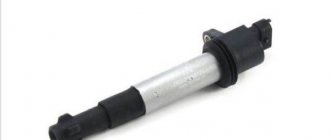
A device function called a slider
The slider is located in the ignition distributor. You can find it right under the lid. By design, runners are quite simple devices consisting of plates (central and spacer). Despite the fact that the models of distributor runners are different, they all have the same design.
One of the varieties of runner
These devices have an important function regarding sparking. We can say that the proper operation of the internal combustion engine directly depends on the slider.
You should know that the distributor rotor is a part of old cars equipped with a carburetor engine system. The slider is made of plastic and has a high-voltage contact inside. When the distributor operates and rotates, the contact of the slider is in direct contact with the contacts of the cover. Thus, the spark that is so necessary for the car is set.
In technical terms, the distributor rotor is needed to transmit high voltage current. The transmission goes from the ignition coil to the spark plugs through armored wires.
Fixing the slider on the distributor
The rotor is fixed directly to the distributor drive (shaft), and the rotation is set in such a way that for 1 revolution of the runner there are 2 revolutions of the crankshaft. It is in this way that the discharge is transmitted to the spark plugs in a strictly defined order.
On a distributor drive, the slider is fixed rigidly so that it does not jump off when the shaft rotates. When rotating, the side contact of the rotor contacts the CG (contact group) pressed into the distributor cap.
Interesting. The distributor cap is in the same position regularly. It does not move, but the sliding contact, “running” next to the electrodes of the cover, forms an alternating and short-term electric arc. This also explains the transmission of the discharge.
On some cars, ignition systems have two working contacts on the slider. This is, in principle, a working classic Twin Spark ignition circuit from the Italian company Fiat. One of the contacts is implemented closer to the center, the other - as far as possible. In this way, the contacts correspond to the cover electrodes, packaged according to the same principle. And most importantly: this scheme ensures complete isolation of the CGs from each other.
Twin Spark ignition system
Twin Spark is considered one of the first systems used for effective afterburning of fuel in the combustion chamber of a car. The system has a simple design, but is very effective and economical.
Causes of coil failure
Partial damage to the ignition coil leads to unstable engine operation, and its complete breakdown makes it impossible to start the engine. That is why, when the engine stalls, loses power, or other signs of unclear operation, one of the first actions should be to check the ignition coil. This element fails quite rarely, and the malfunction, as a rule, is as follows:
- Insulation damage due to extreme heat, vibration or high voltage, which in turn leads to a short circuit in the coil windings;
- Overload caused by faulty high-voltage wires or spark plugs can cause the winding in the coil to break.
Design and principle of operation of a typical ignition system
Ignition system components
On the technical side, the ignition system is part of the engine electrical equipment complex. Structurally, it consists of the following elements:
- Battery or other power source. It supplies a low voltage of 12 volts to the network.
- Switch. When you turn the key, the switch closes and low voltage flows into the energy storage device.
- Energy storage. There are two types: inductive (a transformer-type ignition coil that converts low voltage into high voltage up to 30 thousand volts) and capacitive (capacitor).
- Energy storage and distribution control unit. Depending on the type of ignition system, this may be a chopper, a transistor switch, or an ECU (electronic control unit).
- Distributor. This unit can be mechanical or electronic. It supplies certain candles with energy at a given point in time.
- High voltage circuit wires. They supply high voltage to the electrodes of the spark plugs.
- Spark plug.
The operation of the ignition system is based on the following principle: when low-voltage voltage is supplied to the network, energy is accumulated and converted, which is then distributed among the spark plugs, on the electrodes of which a spark is formed, provoking the ignition of the air-fuel mixture.
Methods for checking the ignition coil
Checking the ignition coil using the “old-fashioned” method can damage the electrics of a modern car
To properly check this car part yourself, it is recommended to perform certain steps step by step. First of all, after removing the coil, you need to visually inspect it and make sure that there are no external signs of a short circuit: black dots indicating burnout, cracks, or other signs of breakdown.
In our country, for a long time, there were two equally popular ways to check the ignition coil for functionality: by checking the spark between the car body and the spark plug, or by measuring the resistance of the windings with a multimeter (tester). The use of the first method can be fatal not only for the coil, but also for the electronics of most modern cars, so its use is categorically not recommended by manufacturers. It is safer to check this component of the car with a measuring device.
Types of faults
As a rule, if the distributor slider is in order, then the car engine starts the first time, without any problems. But when difficulties are observed with the plant, this indicates a damaged or broken rotor (provided that the problem is not elsewhere).
Breakdown of the distributor slider
The most common malfunction of the distributor slider is its breakdown. It can be external or internal. Obviously, the external one is determined by noticeable signs - a black mark, the internal one must be checked by the presence of a spark (details below).
The breakdown occurs due to metallization of the channel. For preventive purposes, metallization should be checked regularly. This is done using a multimeter or other similar device. The channel is checked for moment of resistance. The probes of the device are connected to the place of the slider where there is doubt about breakdown.
You should know that the spark can escape either completely or partially through the formed channel.
Malfunction of the contactless distributor.
When operating contactless distributors, the main malfunction is a malfunction of the hall sensor or inductive sensor. Minor wear and play in the bushings and bearing of the movable contact plate do not affect the operation of the distributor until the sensor rotor touches the stator.
Such malfunctions as breakdown of the slider, burning of its resistance. It can also break through the distributor cap between the cylinders. This malfunction is typical for non-contact distributors, since the secondary voltage in these systems is twice as high as in a contact one.
admin23/04/2011
Subscribe to comments
- Vlad — November 12th, 2012 at 12:54 pm
Good afternoon, I have a Toyota Kaldina that stopped starting, at first it failed, then I changed the explosive wires, the ignition coil, and the slider in the distributor. and it stopped starting altogether. I unscrewed the spark plug and saw a red spark and a velvety black carbon deposit on it, i.e. what a dead thing. Question There is a capacitor in the distributor and it looks worn out, sad, now I’m waiting for a new one, I ordered it. Could this be the reason, is this capacitor a noise suppressor or a spark amplifier? The on-board computer has not flashed a check more than once since the date of purchase of the car.
admin — November 12th, 2012 at 05:33 pm
It's hard to say without knowing the type of engine and year of manufacture, or at least the type of ignition. These models were equipped with four types of distributors. The capacitor plays basically the same role in all. In addition to the capacitor, the reason may be in the switch, which is also installed in the distributor. The capacitor can most likely be checked by charging it by connecting it in series to a 220V network with a lamp of no more than 100W. After disconnecting, use a screwdriver with an insulated handle to close the wire to its body. If the capacitor is working properly, a spark will jump. Answer
- Huilo Waffle - April 2nd, 2012 at 10:15 pm
Cool! It helped me! Now it doesn't bother me!!!
- Mikhail - August 26th, 2011 at 15:24
...The capacitance of the capacitor should be in the range of 15-25 mF... Should be 0.15-0.25 μF
admin — August 27th, 2011 at 0:20
Thank you for your comment. I fixed everything. Answer
A comment
Name *
Website
This site uses Akismet to reduce spam. Find out how your comment data is processed.
« Distributor device
Ignition system VAZ - 2105 »
Tags
VAZ, VAZ malfunctions Sensors Ignition Injector Devices Starter Circuits Electric cars Power supply VAZ 2110 gazelle gazelle business recorders car repair
Recent Entries
- Laser headlights.
- Advantages and disadvantages of halogen lamps
- Design and principle of operation of parking sensors
- Multifunctional device Roadgid X7 Hybrid GT
- Malfunction of the GAS ignition system
Archives
Archives Select month September 2022 August 2022 July 2019 December 2022 August 2022 July 2022 June 2022 May 2022 April 2017 March 2022 December 2016 November 2016 October 2016 September 2016 August 2016 July 201 6 June 2016 May 2016 April 2016 March 2016 February 2016 November 2015 October 2015 August 2015 July 2015 June 2015 May 2015 April 2015 March 2015 February 2015 January 2015 December 2014 November 2014 October 2014 September 2014 August 2014 July 2014 June 2014 May 2014 April 201 4 February 2014 January 2014 December 2013 November 2013 October 2013 August 2013 June 2013 May 2013 March 2013 February 2013 January 2013 November 2012 October 2012 September 2012 August 2012 July 2012 June 2012 May 2012 April 2012 March 2012 February 2012 January 2012 December 2011 November 2011 October November 2011 September 2011 August 2011 July 2011 June 2011 May 2011 April 2011
Categories
- Accumulator battery
- Video
- Generator
- Sensors
- Diagnostics
- Ignition
- News
- Equipment
- Devices
- Repair
- Spark plug
- Starter
- Scheme
- Devices
- Electric cars
- Electricity supply
Distributor malfunctions
The following signs indicate that the distributor is malfunctioning:
When there is a spark on the central wire, but not on the spark plug wires, this indicates a breakdown of the slider.
In most cases, the causes of distributor failure are:
Breakdown of the roof and ignition coil occurs due to large gaps in the contacts of the distributor cover and slider, spark plugs and bad candlesticks.
In each of these cases, replacement is required. But at the same time, for almost any car, it is possible to change not the entire distributor, but only its failed part, which is an advantage, since it significantly reduces the cost of repairs.
The most basic check of the distributor is a visual assessment of the condition of the slider, contacts and cover.
In a contactless distributor, the main malfunction is the failure of the hall sensor or inductive sensor.
To check the ignition system and distributor, among other things, observe the spark on the unscrewed spark plug after starting the engine. In garage conditions, you can also check using measuring instruments or indicators.
The distributor capacitor is also one of the parts that often fail. It helps to increase the voltage supplied to the spark plugs when the engine starts. And in order to check it, you need to disconnect it and touch the “ground”, and if a characteristic crackling sound is heard and a voltage drop is observed, the capacitor is working, if this does not happen to the replacement part.
Setting the ignition using a strobe light
You can adjust the ignition timing using a strobe, but the “manual” method has exactly the same effect. The only negative is that it takes longer to set up, but you can find the most effective ignition timing when the engine produces maximum power.
Installing the ignition on a VAZ engine photo
“Strobe” (as it is popularly called) is a device that pulses the crankshaft position mark at the moment of spark formation. To put it simply, while the engine is running, you can direct the beam of this device to a mark that serves to regulate the ignition timing. We see this mark as stationary, although it is located on a pulley or rotating flywheel (depending on the car model).
Checking the performance of correction systems with a strobe:
- We warm up the engine and remove the “choke”; the idle speed should be adjusted to normal (or slightly lower). We remove the vacuum tube that goes from the carburetor to the “vacuum manifold” of the distributor. Next, in this mode, we adjust and check the setting of the initial ignition timing. In the “classic”, this angle should be from 2 to 7 degrees, it depends on the engine displacement. For example, VAZ 2108-2110 - 1100 cm - 6 g, 1300 cm - 1 g, 1500 cm - 4 g. It is better to find out more in the car description).
- As the engine speed increases, to approximately 2000, the advance angle should increase by 5-7 degrees. If there are no changes, this means that the centrifugal regulator is not working. The main cause of failure may be jamming of the centrifugal mechanism, most often this occurs due to oxidation. For repairs, you need to disassemble, clean and lubricate. In addition, the springs of the mechanism often break.
- To check the operation of the vacuum ignition timing regulator, you need to make more effort, since its performance is related to the operation of the carburetor. The most important condition for good operation of the vacuum corrector is that while the engine is running at idle speed, there should be no vacuum in the tube that goes from the carburetor to the “vacuum manifold”. It should only appear when the engine speed increases. The moment a vacuum appears in the tube can be checked by carefully placing the tip of your tongue on it. You need to apply it to the end of the tube that we removed initially. If the carburetor does not provide timely vacuum in the tube, then the vacuum corrector will not work normally, even if the distributor mechanism is fully operational.
Which distributor is suitable for the VAZ-2107
On all carburetor rear-wheel drive VAZ cars, the device has almost identical components and a similar operating principle. Distributors for engines with a volume of 1200-1300 cc differ in that: - the drive rod is 7 mm shorter; — no vacuum ignition timing regulator; — the settings of the weights and springs of the centrifugal regulator are different. For engines with a volume of 1500-1600 cc, all distributors are suitable in terms of mounting dimensions and characteristics. Only “Nivovskie” ones differ. They are tuned for stable traction at low speeds and the VAZ-2107 with such a distributor will accelerate slowly. The brands of “Nivovsky” distributors are: 3810.3706, 038.3706-10. And distributors of brands 0.3706 (contact) and 38.3706 (non-contact) are suitable for the “Seven” and other classic cars.
CHECKING THE IGNITION DISTRIBUTOR. Repair and diagnostics of the electrical equipment system.
How to check the ignition distributor
The main reason for checking the ignition distributor, the engine electrical system, is to check for damage that is not subject to normal repair. Typically, the ignition distributor is checked on a test bench. Before installing the distributor on the test stand, make sure that the condition of the breaker contacts is normal. The lever with a moving contact should not jam on the axis. Check the wear of the textolite block; if the spring of the lever is weakened, or the lever itself is stuck on the axis, the contact group must be replaced.
Contacts that are dirty, burnt or have signs of erosion will need to be treated. For processing, use a velvet file; the use of abrasive materials or sandpaper is prohibited. After cleaning, clean the contacts well.
Wipe the ignition distributor cover from dust and oil residues
When installing the ignition distributor on a control test bench to check the ignition devices, connect it to an electric motor that can adjust the rotation speed.
The control test bench must be able to connect the distributor with the ignition coil and battery, similar to the ignition system diagram.
Connect the terminals of the distributor cover to spark gaps, the interelectrode gap of which is adjustable.
Set the interelectrode gap of the spark gaps to 5 mm, turn on the electric motor, set the rotation speed to 2000 rpm. Then increase the interelectrode gap to 10mm, and check for internal discharges in the distributor. The manifestation of internal discharges can be determined by a characteristic sound, or by an interruption and weakening of sparking at the stand's spark gap.
A serviceable distributor should not make noise at any roller rotation speed
To determine the characteristics of the centrifugal ignition timing regulator, set the interelectrode gap of the bench spark gap to 7 mm. At the stand, turn on the electric motor, the speed should be 150 - 200 rpm.
Mark the value in degrees on the graduated disk of the stand, gradually increase the rotation speed by 200 - 300 revolutions, use the disk of the stand to determine the number of degrees of ignition timing, it should correspond to that shown in the image.
- A - ignition distributor P125.
- B – ignition distributor 30.3706.
- Where is the vertical line? A corresponds to the ignition timing in degrees.
- And the horizontal straight line n is the rotation frequency of the ignition distributor shaft in minutes.
If the characteristic shown in the figure differs from the test indicators, it can be corrected and brought back to normal by bending the springs of the centrifugal regulator weights.
If you need to bring the indicator up to 1100 rpm, bend the thin spring strut, and if above 1100 rpm. min. then bend the thick spring strut. To increase the angle, reduce the spring tension; to decrease it, increase it.
To obtain the performance characteristics of the vacuum ignition timing regulator, set the rotation speed for the roller to 1000 rpm. On a graduated disk, determine the value in degrees at which one of the four sparks occurs and mark it. Next, slowly, as they say smoothly, increase the vacuum and record the number of degrees every 20 mm of mercury, record the number of degrees of ignition timing. Compare the obtained indicators with the values shown in the images.
Where the vertical straight line A is the ignition timing in degrees. And the horizontal straight line P is the vacuum in millimeters of mercury.
Between the various terminals and ground, check the insulation resistance using a megger.
To measure the resistance between ground and the low-voltage terminal of the breaker, it must be done with the breaker contacts open. At 25-30 degrees Celsius, the insulation resistance should be at least 10 MΩ (megohm).
If you measure the capacitance of a capacitor in the frequency range 50 - 1000 Hz, the capacitance should correspond to 0.20 -0.25 µF (microfarads)
The main components of the distributor and a description of its operation
VAZ classic distributor device
Device
The distributor is assembled in a housing. Inside it, a contact group is mounted on a bearing: moving and fixed contacts or a Hall sensor (for contactless ignition). To correct the advance angle, the vacuum regulator can rotate the contact group at a small angle relative to the housing. The capacitor is attached to the bottom of the case with screws. A drive roller is mounted on bushings in the center of the body. Its bottom has splines with which it engages with the drive gear. In the upper part of the roller there are contact drive cams (for contact ignition) or a steel cup with four slots - a screen (for contactless ignition). At the very top, on a steel platform, two weights and two springs of the centrifugal ignition regulator are installed. A plastic housing with a moving contact and noise suppression resistance of the high voltage distributor (slider) is screwed onto the top with two screws. The entire structure is closed with a lid on two spring latches. The body and cover have a tongue and groove so that they fit together in only one position. The cover contains contact terminals for high voltage wires from the spark plugs and from the ignition coil. The distributor is secured to the engine block using a stud, nut and pressure washer. To adjust the ignition timing, the housing can be rotated relative to the block.
Job
The distributor is connected through the drive to the engine crankshaft and rotates with it. For two full revolutions of the crankshaft, the distributor shaft makes one revolution. This is due to the fact that our engine is four-stroke. When installing the distributor in place, the roller is oriented in strict accordance with the operating order of the engine. This is done so that the contacts open and the spark jumps on the spark plug when the piston of each cylinder, compressing the combustible mixture, does not reach top dead center (TDC) by a few millimeters. This is called ignition advance. When the number of revolutions increases, the distance must be increased, and when it decreases, it must be decreased, which is what the centrifugal regulator does. Its weights, under the influence of centrifugal force, which is greater the higher the engine speed, diverge to the sides and move the cams relative to the roller, making ignition “earlier.” When the engine speed decreases, the springs return the weights to their place and the ignition becomes “later”. This is necessary to increase engine power and efficiency. In addition to the centrifugal one, a vacuum ignition timing regulator is also installed on the distributor. Its function is to fire “earlier” at low throttle opening angles and “later” at sharp throttle opening angles. At idle and at full throttle, the vacuum seal does not work. The regulators are adjusted only at the stands, so there is no need to change the settings yourself.
Distributor repair
Repairing a distributor is a rather complicated procedure, requiring the repairman to know the structure of the unit and the electronics in general. The complexity of the distributor design, the difficult connection diagram and the lack of electrician training among motorists reduce the possibility of its own repair to almost zero. It is based on this that garage technicians often prefer to completely replace a faulty distributor.
Often this approach is completely justified, as it significantly saves motorists’ time. However, when deciding to replace the distributor, you need:
- firstly, try to diagnose the exact malfunction of the device (for example, incorrect operation of high-voltage wires does not require a complete replacement of the distributor, because it is much easier and cheaper to simply change the wiring);
- secondly, consult with a specialist in the field of repairing ignition systems and make sure that it will be cheaper to replace the distributor rather than have it repaired by an electrician.
Let's say the need to install a new distributor is confirmed. In such a situation, it is quite advisable to save some money and carry out the replacement yourself. To organize the repair you will need:
- set of wrenches;
- spark plug key;
- screwdriver;
- rags;
- new distributor.
The repair procedure is as follows:
First of all, you need to unscrew the spark plug of the first cylinder and determine where the distributor is located specifically on your model; Next, we proceed to align the motor shafts in the desired position. To do this: jack up the front wheel on the right; close the spark plug hole with your finger; turn the wheel until air begins to press on your finger; Next, we gain access to the timing belt, remove the crankshaft flywheel plug and align the marks of the shaft pulley and the engine block.
We remove the distributor
This is where it is extremely important to remember the connection diagram for high-voltage wires. It's best to take a couple of photos of the attached distributor and mark each attached spark plug wire accordingly for identification.
After the connection order has been successfully fixed, you can remove the part. To do this, there is a distributor cover, the spark plug wires and fasteners are unscrewed from it, after which the unit is successfully removed; Then the most important part begins - installing the distributor. The unit is connected in the following order: the distributor is installed in the vehicle structure in the same way as the old unit; the gaps of the mechanical slider located under the distributor cover are set (if required, how to adjust the distributor - we’ll talk below); spark plug wires are mounted to it; low voltage wire is connected; the ignition timing is adjusted (again, if required).
In general, there are no particular difficulties in installing a new distributor. It is much more difficult to understand how to check the distributor for a particular malfunction, because this requires much more knowledge than is required to implement the process described above.
Operating principle of the distributor
In many ways, the operating principle of the distributor remained unchanged for many years. In VAZ cars, such as VAZ 2109, 2106, 2107, 2108, an ignition system of this type was used almost until the end of the last century.
The basis of the work is the connection of the distributor with the engine crankshaft. When the piston in the first cylinder takes the position corresponding to TDC, the breaker contacts open, a high voltage appears in the ignition coil, directed through a slider located in the distributor cover to the spark plug of the first cylinder.
There the combustion of the fuel assembly occurs, and the crankshaft continues to rotate. In addition to moving the pistons, it causes the breaker cam to rotate. When in another cylinder another piston occupies a position corresponding to TDC, at this moment the breaker contacts in the distributor open again, and a high-voltage voltage is generated in the ignition coil and supplied to the desired spark plug.
This joint rotation of the crankshaft, the breaker cam and the distributor slider ensures that a spark appears where and when needed. However, this does not cover all aspects of how the distributor works. To understand its operation, it is necessary to touch upon such concepts as the angle of the closed state of contacts (UZSK) and the ignition timing angle (IAF)
UZSK
A concept such as UZSK characterizes the time when the breaker contacts are closed. In essence, this is an indirect characteristic of the accumulation of energy in the coil after the completion of spark formation. UZSK directly affects the amount of energy spent on sparking and, accordingly, on engine operation.
In cases where the distance between the contacts is small, the coil will not accumulate the necessary energy and the spark energy will be low, which will lead to interruptions in the operation of the motor. A large gap also leads to interruptions, since the contact breaking time is reduced and the coil does not have time to fully discharge.
Each ignition system has its own optimal UZSK, to ensure which, if necessary, the distributor must be checked and adjusted.
UOZ
This concept concerns the moment of ignition of a fuel assembly. The fact is that its combustion does not occur instantly, and often, to ensure optimal conditions for such a process, it must begin earlier than the piston reaches the TDC position. The OZ characterizes the time by which the appearance of a spark precedes the appearance of the piston in the TDC position.
It is constantly changing, and its value completely depends on the operation of the motor under specific conditions, i.e. depending on the load, vehicle speed, quality and type of fuel used. To ensure optimal combustion of the fuel assembly, the distributor contains a centrifugal regulator and is also connected to a vacuum regulator.
VACUUM REGULATOR
It is this device that can change the OZ if necessary. As soon as the motor load changes, appropriate adjustments are made to the operation of the distributor device parts.
Important! The load is determined using the throttle valve.
The vacuum regulator of the distributor is a closed cavity. To ensure better performance, the design is divided by a diaphragm. One cavity goes directly to the carburetor.
When a vacuum occurs, the diaphragm begins to move. As a result, pressure is exerted on the movable disk and the breaker cam. The response time of the latter is adjusted depending on the current situation.
Attention! The distributor changes the moment of spark formation, thereby affecting the performance characteristics of the motor.
OCTANE-CORRECTOR
This is a very important element in the distributor design. Without it, the entire system could not function normally. The unit changes the SOP depending on the fuel that is currently being used.
By its design, this distributor element resembles two plates with an arrow. The same arrow is installed on the engine. There are special lines on it, through which the ignition angle is adjusted. It is almost impossible to do without this part when refueling different types of gasoline.
We recommend: Review of the best station wagon models
CONTACTLESS SYSTEMS
Technologies do not stand still. Every year, the automotive world is rocked by new innovations. This is precisely what innovation became in its time, supplementing the distributor design with switches.
Attention! In switches, the signal is supplied to the control electronic module, and not to the coil.
The second name for non-contact systems in the distributor device is Hall sensors. The simple design of these devices ensures uninterrupted signal supply. The sensors themselves work due to changes in the magnetic field.
Checking the ignition coil with a multimeter
Diagnostics of the electronic engine control system and the electrical circuit of the distributor
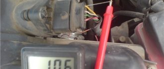
The ignition coil is located in the distributor, and to check the voltage it is necessary to bend the latched clamp and remove the wires that go to it from the distributor. Next, you need to take a multimeter and set the parameters on it for measuring voltage. After this, one of the multimeter wires is applied to the terminal of the ignition coil, and the second to the car body (that is, to ground).
The result of such a measurement, with a working ignition coil, should be 12 Volts, displayed on the multimeter. If there are problems with the electronic engine management system or the electrical circuit of the distributor, the multimeter will show 0 Volts.
Checking the secondary winding for open circuit
To carry out such a diagnostic procedure, you need to set the multimeter to the mode for measuring electrical resistance (Ohms). Next, we connect one of the wires of the diagnostic device to the positive or negative terminal of the ignition coil, and the second to the central terminal.
If your measurement results in a value of about 6-8 kOhm, this is considered normal for most coils. Some can produce values up to 15 kOhm, which is also considered acceptable, but it is better to clarify this parameter in the technical documentation of the car. In the case where the deviations in the measured results are serious, in relation to the figures indicated in the technical documentation, we can talk about a break in the secondary winding.
Checking the primary winding for open circuit
The procedure for diagnosing the primary winding of the ignition coil is practically no different from checking the secondary winding. Again, take the multimeter, which is set to measure electrical resistance, and connect its wires to the positive and negative terminals of the ignition coil, that is, to the external contacts (in most cases).
If, as a result of the measurement, the multimeter shows values of about 0.5-2 Ohms, then there are no problems with the primary winding and it is operating normally. When the resistance differs from these values, the fact of a break in the primary winding is stated.
Distributor design
The distributor circuit assumes the presence of such elements as:
- low voltage current breaker;
- high voltage current distributor;
- centrifugal ignition timing regulator;
- vacuum ignition timing regulator.
The distributor circuit is designed so that at a certain moment the breaker opens the primary ignition circuit, as a result of which a high voltage current is created in the secondary winding of the ignition coil. Through the distributor, this current is transmitted to the spark plugs in certain cylinders. The regulators automatically adjust the ignition timing, which depends on the current operating mode of the engine.
Distributor device
The distributor breaker is an electromechanical part and consists of the following parts:
- shaft;
- movable contact plate;
- movable contact plate;
- capacitor;
- frame.
The breaker shaft consists of two main parts. On one of them, depending on the type of breaker, cams are installed, the number equal to the number of cylinders in the engine. This distributor device is not very reliable, since a large number of contacts, as well as the presence of moving parts, lead to regular problems with this unit.
The distributor device, as well as its use in general, are outdated from the point of view of modern electrical equipment, but in our country there are still a lot of carburetor engines, so the problem of the performance of this unit is currently relevant.
As for where the distributor is located in the car, most often it can be found under the hood next to the engine, near the cylinder head or on it. Although the exact location of the node depends solely on the model of the machine.
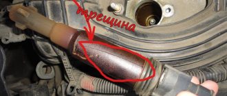
Cover and signs of its malfunction
Separately, there are symptoms that clearly indicate problems with the lid. Experienced motorists immediately distinguish them.
- “Trippling” of the power plant while the vehicle is moving, especially in damp, rainy weather.
- The speed does not increase while driving.
- An increase in the symptoms described above after driving a car through puddles.
In any case, self-repair and adjustment of automotive components is much better than completely overhauling the car or replacing expensive spare parts. It is advisable to inspect the distributor cover yourself under good lighting.
Traces of punctures, plaque, mediocre condition of the coating, the presence of moisture or condensation inside the distributor - all this may indicate a malfunction of the cover.
Cover malfunctions
The microcracks themselves may not be visible at first, but their presence is already enough for the car to not function correctly.
Eliminating defects is a responsible process. In the case of the distributor cap, you can occasionally coat the surface with silicone-based sealant or remove deposits from the contacts. But if the malfunction is more complex, only a complete replacement of the cover will help.
Replacing the cover
Replacing it is not a painstaking operation, but it is worth showing careful attention. It is worth remembering that sometimes the nuances make all the difference for a beginner who decides to do auto repair on his own. For example, if the armor wires are incorrectly connected to the cylinders, the latter simply will not work.
The sequence of connecting the armored wires is, as usual, marked on the internal combustion engine itself or can be found in the car’s operating book. All the same, whatever one may say, it is easier to make marks on the elements themselves during the process of replacing them. The masters themselves recommend doing this.
As a rule, the documentation of some car models indicates the location of only one armored wire going to the 1st cylinder. The remaining wires are installed by the car owner himself against the rotation of the emergency.
The entire operation takes no more than 30 minutes. The price of a new cover ranges from 5 thousand rubles, which is quite inexpensive. After the cover is replaced, it will not be superfluous to treat all armored wires and the surface of the cover with a special composition, which significantly minimizes the likelihood of moisture getting inside.
During the process of updating the cover or slider, removal of the distributor will not be necessary. The cover is dismantled after disconnecting all armor wires.