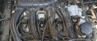
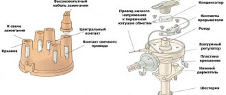
The ignition coil on a VAZ 2107 car is used to convert a low voltage current of 12V into a high voltage current of 11-20kV, which is necessary to break down the air gap between the electrodes of the spark plug and form a spark that ignites the working mixture. On a VAZ 2107 car with a contact ignition system, an ignition coil of type B-117 A is used. The ignition coil is installed in the engine compartment of a VAZ 2107 car and is secured with nuts on two studs to the left mudguard. The ignition coil is a transformer with a magnetic core, consisting of a core and an outer magnetic circuit, and two windings - primary and secondary. The ignition coil core is made of electrical steel plates and is located in a frame on which the secondary winding is wound. The primary winding is wound through the insulator on top of the secondary winding. The outer magnetic circuit consists of a rolled strip of electrical steel. The ignition coil housing is made of steel, the ignition coil housing has a cylindrical shape. On top, the ignition coil housing is hermetically sealed with a cover made of insulating material. To improve cooling and insulation, transformer oil is poured into the ignition coil housing. The ignition coil cover has a high-voltage and two low-voltage terminals. The high-voltage output is connected to the secondary winding and, through a contact bolt and spring, to the core. The end of the primary winding is connected to one low-voltage terminal of the ignition coil, connected by a wire to the contact group of the ignition distributor. Voltage from the ignition switch is supplied to the “+B” terminal of the ignition coil.
On a VAZ 2107 car with a contactless ignition system, ignition coils of type 27.3705 (with an open magnetic circuit, oil-filled) or type 3122.3705 (with a closed magnetic circuit, dry) are used.
Checking the ignition coil of a VAZ 2107 car
To perform work on checking the ignition coil on a VAZ 2107 car, you will need a multimeter.
For clarity, we carry out the test on a removed ignition coil.
1. Disconnect the wires from the ignition coil terminals (see “Removing the ignition coil”).
2. Clean the ignition coil from dirt and rinse it with white spirit or kerosene.
3. Connect the ohmmeter probes to the terminals of the primary winding of the ignition coil and measure the resistance. The resistance of the primary winding of the B-117 A ignition coil at a temperature of 20″C should be 3-3.5 Ohms (for an ignition coil type 27.3705 - 0.45-0.5 Ohms).
4. Having connected the ohmmeter probes to the high-voltage and the “+B” terminal of the ignition coil, we measure the resistance of the secondary winding. The resistance of the secondary winding of the B-117 A ignition coil at a temperature of 20″C should be 7.4-9.2 kOhm (for a coil type 27.3705 - 5-0.5 kOhm).
Removing the ignition coil from a VAZ 2107 car
2. On a VAZ 2107 car, disconnect the wire from the negative terminal of the battery (see “Battery for a VAZ 2107 car - removal and installation”).
3. Disconnect the wire from the high-voltage terminal of the ignition coil.
4. Using an 8 mm wrench, unscrew the nuts on the ignition coil terminals and disconnect the wires. A red-blue wire is connected to the “+B” terminal of the ignition coil.
5. Using a 10 mm socket wrench, loosen, without unscrewing completely, the two nuts securing the ignition coil to the mudguard studs.
6. Sliding the ignition coil, remove the coil from the studs.
Installing an ignition coil on a VAZ 2107 car
Installing the ignition coil on a VAZ 2107 car is performed in the reverse order. In this case, the tip of the “mass” wire is installed between the ignition coil eye and the washer.
Diagnostics and replacement of the ignition coil
The type of coil used on the VAZ2107 is B-117A, it was specially designed for classic cars with a contact ignition system. This device consists of the following parts:
- core;
- external magnetic circuit;
- primary and secondary winding.
The core is a set of plates made of steel of special electrical grades. This part is the basis for coils isolated from each other. The coil has a metal body filled with transformer oil. The cover, made of dielectric, has two contacts for powering the primary coil and one terminal for the high-voltage wire.
Device and connection diagram
Inside the ignition system module (catalog number 2111-3705010) there are voltage converters and electronic components that distribute pulses based on signals from an external sensor. The elements are connected by jumpers, which are attached with tin-lead solder. The housing is made of dielectric material that does not collapse under the influence of vibrations and temperature changes. The outputs are equipped with contact plates to which mating elements of high-voltage cables are connected.
Ignition system diagram.
Connection instructions
Switching algorithm:
- Install the coil onto the cylinder block and secure with screws.
- Connect the plug of the engine wiring harness.
- Connect the outputs of the coil to the spark plugs with high-voltage wires, observing the serial numbers of the cylinders. The numbers are printed on the module body. On the engine, the cylinders are counted from the accessory drive pulley.
- Connect the battery and crank the crankshaft with the starter to start the engine.
Procedure for checking ignition system devices
The main reason for the failure of this device is a wire break in the primary or secondary winding. This ignition system device is checked using a multimeter set to resistance measurement mode. The operation can be performed either directly on the car or after it has been dismantled.
Open the hood of the VAZ2107 car and disconnect the battery. The coil installed on the mudguard in the engine compartment is disconnected from the on-board network and cleaned of contaminants. At the first stage, we check the resistance in the primary winding; its value should be in the range from 3.0 to 3.5 Ohms. We perform the same operation for the secondary winding, acceptable values are from 7.4 to 9.2 kOhm.
Checking the ignition module
Checking the ignition module for functionality is carried out in the following ways:
Replacing the ignition module with a known good one
1. The easiest way is to connect a known working module. In this case, the devices must be completely identical, the high-voltage wires are in good condition, and the reliability of the contacts has been checked.
Checking the contacts on the ignition module
2. Moving the module, which allows you to identify unreliable contacts. To do this, move the wire block and the module itself. If during exposure the engine reacts by changing its operation, then the cause of the problem lies in poor contact.
Measuring resistance at the terminals of the ignition module
3. Resistance measurement. To do this, you will need a tester switched to ohmmeter mode. Measurements are carried out on the paired terminals of the module between cylinders 1 and 4, as well as cylinders 2 and 3. The resistance value should be the same and approach 5.4 kOhm.
Checking the ignition module using a tester
4. Check the voltage with a tester. One probe of the device is applied to contact A of the block, the second to ground. After turning on the ignition, take readings from the device. If the wire is in good condition, it will show a voltage of 12 V; if it is missing, check the fuse protecting the ignition module. Then check the continuity of the circuit with a 12 V test lamp. Apply one end of the wire to contact A and rotate the starter. If the lamp does not blink, the circuit is broken. The procedure is repeated in a similar way with other contacts.
Diagnostics of the ignition module with professional equipment
5. Diagnostics at a service station by connecting a computer with special software to the computer. Malfunctions are detected in the form of errors indicated by an alphanumeric code, after which a more in-depth diagnosis of the malfunction is carried out to make a decision - repair the ignition module or replace it. A similar check is carried out at a specialized service station using an oscilloscope.
Replacing the device
If the indicators do not correspond to the above values, the ignition coil is considered faulty. Such a device must be replaced with a working one, which can be purchased at almost any spare parts store. When purchasing the device, you must inspect it and check the availability of documents: technical passport and certificate.
Removing the ignition coil on a VAZ2107 car is carried out with the battery disconnected. Use a wrench to unscrew the nuts on the contact and mounting studs. The faulty device is removed. A spare part is installed in its place and secured and connected. Now you can connect the battery and start the engine.
How to check the ignition coil of a VAZ 2106
How to check the ignition coil of a VAZ
2107 - 2101
carburetor coil in a car is not the least important ignition detail due to which the car may not work. To check the coil we will consider two options and with these two options everyone will find a convenient option for themselves. The first option will be considered how to check the coil on a VAZ with a multimeter the second option, as I said, will be simpler, but the efficiency is 70%: how to check the ignition of a VAZ 2107 - 2106 carburetor we will consider without a multimeter; the second option is probably the simplest, we will check it directly on the car, so let’s get started.
This is interesting: How to correctly respond to an inspector who demands to show documents
Distributor diagnostics
Malfunctions of the ignition system can be caused by a breakdown of a component such as a distributor. Several types of problems may arise in it that can damage the contact ignition of the VAZ 2106. So, if the coil is working properly, then the problem in the operation of the system is due to the fact that the distributor, which has the contact ignition of the VAZ, has broken down.
To check, you need to remove the cover and inspect it. All contacts and contact angle must be free of damage and cracks. After inspecting the cover, you need to check the distributor slider. Sometimes cracks appear on this element as a result of wear, which leads to breakdowns to ground.
After inspecting the slider, the breaker contacts are examined, if necessary, they are cleaned, and the gap between them is checked. It is imperative to inspect the capacitor, since most often it is the one that is faulty, which is the reason for the failure of the vehicle systems. If there is no charge accumulation after applying voltage, the capacitor must be replaced.
When checking the ignition of the VAZ 2106, we must not forget about the spark plugs. The fact is that the normal operation of the system depends on the gap between the spark plug electrodes. The spark plug gap should be 0.4-0.8 mm. Increased play leads to heating of the coil and, as a result, possible breakdown of its windings.
The VAZ ignition relay is designed to protect the system from sudden changes in voltage at the moments of switching on and off. It protects the contacts of the lock and the breaker from burning, thereby ensuring the long service life of these components. The contacts in the VAZ ignition relay open almost instantly, which prevents the formation of sparks during operation.
The advantage that the VAZ ignition relay has over other elements of the system is the ease of its replacement in case of failure. When repairing a car, it is better to have a special manual on hand. As a rule, such a publication, in addition to a textual explanation, contains photographs of vehicle components, which facilitates repairs.
Often the reason for the disappearance of the spark on the spark plugs is a malfunction of the ignition coil (IC). The article describes the device, how to check the ignition coil of a VAZ 2106, its malfunctions and how to eliminate them.
How to check the ignition of a VAZ 2106 with a multimeter
In order to check the coil with a multimeter, we need the multimeter itself and, of course, the ignition coil itself. take a multimeter and set it to 200-ohm, then check the terminals (B - K), the resistance should be at least in the range of 04.0-ohm, the resistance range is from 03.8 to 04.5-ohm, this is the norm; there’s clearly something wrong with the coil; now we need to check the high-voltage part; we set it measurement mode 20-klom 1 any probe on mark B or K another on the high-voltage contact resistance 7.6 klom 7 to 8 klom this is the norm This means your coil is intact, but also do not forget that there may be an internal breakdown of the coil, that is, a breakdown of the insulation between the high-voltage and low-voltage winding and also the interturn one, and you also need to check the case, that is, also at 20 kL, we leave the relative mass for each contact, we check because we came across coils, so we check everything is fine on the case, it breaks through, and if there are no short circuits between the winding and interturn circuits, then it will function.
How to check the malfunction of the VAZ 2114 ignition module on your own?
In order to start checking, you will need a measuring device - a tester. Before starting the measurement, the wire blocks are removed from the connectors. Each block has its own slot (A, B, C, D).
Checking the VAZ 2114 ignition module with a multimeter:
- turn on the car engine;
- set the multimeter switch to measure direct current up to tens of volts;
- one of the probes of the device is connected to connector D, the second to ground. If there is power, the screen will show 12 volts;
- switch the multimeter to ohmmeter mode up to tens of ohms;
- one probe is connected to connector C, the other to ground. If everything is in order, the device will show less than 1 Ohm;
- switch the multimeter to voltmeter mode up to tens of volts;
- one probe is connected to connector B, the other to ground. If a voltage of at least 0.3 Volts is displayed, then everything is fine (a clear pulse comes from the Hall sensor);
- The last measurement with connector A is carried out exactly as in the previous case.
Checking the ignition unit with a multimeter
Before you start testing the ignition module, you should carefully check the quality and reliability of the contact of all wires approaching and departing from it - perhaps this is the only reason.
Another testing method is to directly check the secondary coils for breakdown.
How to check the ignition coil of a VAZ 2107 - 2106 carburetor
The second option is simpler: we pull out the high-voltage wire from the distributor that leads to the ignition coil, bring it to ground without touching about 0.5-0.9 millimeters and turn it with the starter, the spark should be saturated with a blue-yellowish tint and loud, if this is not the case, you can safely change your voltage loss (Make sure that the battery not discharged! How to check the VAZ generator ) also if there is a second ignition coil, you can simply throw wires on it and check to start the engine and see how it works or, as mentioned earlier, for a spark by weight how to install the ignition on a VAZ 2106 .
Briefly about ignition
To understand why there is a reel in a car (this is a popular name), and what part it takes in ensuring movement, you need to at least generally understand the structure of ignition systems.
A simplified diagram of how the reel works is shown below.
The positive terminal of the coil is connected to the positive terminal of the battery, and the other terminal is connected to the voltage distributor. This connection scheme is classic and is widely used on VAZ family cars. To complete the picture, it is necessary to make a number of clarifications:
- The voltage distributor is a kind of dispatcher that supplies voltage to the cylinder in which the compression phase has occurred and the gasoline vapors should ignite.
- The operation of the ignition coil is controlled by a voltage switch; its design can be mechanical or electronic (contactless).
Mechanical devices were used in old cars: the VAZ 2106 and the like, but now they are almost completely replaced by electronic ones.
A little theory.
On the “seven”, as a rule, contact ignition systems of the B-117 A type are used. The coil itself is located in the engine compartment and is attached to the left mudguard with two studs. Also found on the VAZ 2107 are non-contact ignition systems (BSZ), in this case, coils of type 27.3705 are used, oil-filled with an open magnetic circuit, as well as type 3122.3705 dry coils with a closed magnetic circuit.
Signs of a faulty ignition coil
If, after turning the key in the ignition switch, you hear that the starter is turning, but the engine does not start, then, as a rule, this may mean that the ignition coil is not working correctly or has failed. Although there are many reasons why the engine does not start when you try to start it: spark plugs, explosive wires, problems in the fuel system (pump, fuel filter, clogged line), and so on.
But if, after all, the reason is in the ignition coil, then this can be understood by the following symptoms:
- There is no spark at the spark plugs;
- There is no current on the BB wires;
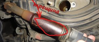
- Visual defects (cracks and chips on the reel body);
- A burning smell under the hood, which leaves traces of melting of the ignition coil (the primary or secondary winding has burned out).
Checking the ignition system on a VAZ 2106 car
| WARNING The VAZ 2106 is equipped with a contact ignition system. A voltage of approximately 24,000 V is supplied to the high-voltage wires (as an option, a contactless high-energy ignition system can be installed on a VAZ 2106 car - a voltage of approximately 40,000 V). At low current levels, this voltage is not life-threatening, but can lead to electrical injury. Therefore, if you handle a high-voltage wire with the ignition on, use a thick rubber glove or, as a last resort, pliers with insulated handles. |
To check the ignition system on a VAZ 2106 car, you will need: slotted and Phillips screwdrivers, pliers with insulated handles and a tester or 12 V test lamp with two wires connected to it. You can also use a car portable lamp.
RECOMMENDATIONS Before checking the ignition system, place the gear shift lever in neutral and leave the parking brake on.
1. With the ignition off on the car, check the integrity and fit of the high-voltage wires in the ignition distributor cover, as well as the fit of the high-voltage wire in the ignition coil. 2. Check the wires going to the ignition coil and their connections. Also check the wire connecting the distributor and the ignition coil.
3. Turn on the ignition on the VAZ 2106 car. Check if current is supplied to the ignition system. Connect one wire of the tester or warning lamp to the “+B” terminal of the ignition coil, and the other to ground. If no current is supplied to the ignition system, then the fault is in the ignition switch or in the wiring from the switch to the ignition coil. In order to get to the nearest car service center, you can apply emergency power to the ignition system. To do this, connect the “+B” terminal of the ignition coil and the “+” terminal of the battery with an additional wire. Fasten the wires securely. Keep in mind that now, in order to turn off the engine, you will need to disconnect the additional wire from the “+” terminal of the battery.
WARNING If strong sparking is noticed when connecting to the “+” terminal of the battery, this method will have to be abandoned - most likely, the wiring is shorted to ground.
5. If there is no spark between the spark plug electrodes, remove the distributor cover. Check if there is a gap between the breaker contacts. To do this, use a special wrench to turn the engine crankshaft so that the top of the ignition distributor shaft cam is strictly opposite the textolite pad of the moving contact lever. The gap between the moving and fixed contacts of the breaker should be 0.35-0.4 mm.
NOTE When using an autotester, the closed state angle of the contacts (UCS) is measured, which should be 55°. The measurement is carried out with the engine running! An approximate value can be obtained by cranking the engine crankshaft with the starter.
6. If the gap (UZSK) does not meet the standard, adjust it and be sure to check the ignition timing.
How to check the ignition coil of a VAZ 2107?
Checking the ignition on a VAZ 2107 is performed using a multimeter or ohmmeter.
- It is necessary to disconnect the wires from the ignition coil terminals.
- And connect the multimeter electrodes to the terminals of the primary winding of the ignition coil.
- Check resistance. The resistance of the primary winding on a coil of type B-117 A, at a temperature of 20°C should be approximately 3-3.5 Ohms, for a coil of type 27.3705 - 0.45-0.5 Ohms.
- Connect a multimeter to the high-voltage terminal “+B” to measure the resistance on the secondary winding. The resistance of the secondary winding on a coil of type B-117 A at a temperature of 20°C should be 7.4-9.2 kOhm, for another type of coil - 27.3705 (normal resistance is considered to be 5-0.5 kOhm).
In this video you will learn in more detail how to check the ignition coil
Checking the ignition coil of VAZ 2104, 2105, 2107 cars: 2 comments
Check the spark directly from the coil. The central wire must be pulled out of the distributor cover and brought to ground (insert the spark plug and place it on the engine) and turn the engine with the ignition on. If there is a spark, the coil is normal; if not, then you need to check other parts of the ignition system. For example, if you have contactless ignition, then if the switch or Hall sensor malfunctions, there will be no spark. It is also worth checking whether voltage is supplied to terminal “B” of the coil.
Is the difference in the secondary winding 0.5 kOhm critical? Should I change the coil? There is no spark. I have already checked everything that can be done, rang the coil and these are the results
How to replace the ignition coil on a VAZ 2107
In most cases, the coil is irreparable, that is, it is almost impossible to repair it, so if the ignition coil malfunctions, it will have to be replaced. Replacing the coil on a VAZ 2107 is quite simple; any novice car owner can handle this task.
To work you will need:
- Socket heads for “8” and “10”;
- New ignition coil.
The actual replacement process itself:
1. First of all, remove the “-” terminal from the battery.
2. Next, we remove the central explosive wire of the coil output; to do this, simply pull it up with a minimum of effort.
3. Using the “8” socket, unscrew the nuts securing the terminals of the wires connected to the coil contacts.
4. Next, remove the coil itself; to do this, unscrew the two nuts securing the coil.
5. Remove the ignition coil and put a new one in its place.
Further assembly is carried out in reverse order.
Current:
Thank you for your attention, see you again at VAZ Do-It-Yourself Repair.
Distributor
Contents
Before installing the ignition distributor on the stand, check the condition of the breaker contacts, whether the lever with the moving contact is stuck, as well as the contact pressing force, which should be 500-600 gf. Check the wear of the breaker lever pad. In case of wear, set the required gap between the breaker contacts.
If the breaker contacts are dirty, burnt or eroded, clean them with a file. Sandpaper and other abrasive materials cannot be used for this purpose. After cleaning, wipe the breaker contacts with chamois soaked in gasoline. Then pull back the lever so that the gasoline evaporates, and wipe the contacts again with dry chamois. Instead of suede, you can use any material that does not leave fibers.
The contacts must touch the entire surface. If this does not happen, then bend the stand bracket to adjust the position of the fixed contact. Do not bend the lever with the moving contact. Wipe the ignition distributor cover from dirt and oil. By slightly lifting the ignition distributor cover, check whether the rotor contact is against the cover electrode at the moment the breaker contacts open.
Checking work
The ignition distributor is installed on a control and test bench for checking electrical devices and connected to an electric motor, the rotation speed of which is regulated. Connections are made to the ignition coil and to the battery. The four terminals of the cover are connected on a stand to spark gaps, the gap between the electrodes of which is adjustable.
Set a gap of 5 mm between the electrodes of the arresters, turn on the electric motor of the stand and rotate the distributor shaft for several minutes clockwise at a frequency of 2000 rpm.
Then increase the gap between the electrodes to 10 mm and monitor whether there are internal discharges in the ignition distributor, which are detected by sound or by weakening and interruption of sparking on the test bench spark gap.
During operation, the ignition distributor should not produce significant noise at any shaft rotation speed.
Removing the characteristics of the centrifugal ignition timing regulator
Install the ignition timing regulator on the stand and make electrical connections in accordance with the instructions on the stand. Turn on the electric motor of the stand and rotate the ignition distributor shaft at a frequency of 300-400 rpm for P125 distributors and 150-200 rpm for 30.3706-01 distributors. The value in degrees is measured on the graduated disk, according to which one of the four sparks is obtained.
By increasing the rotation speed and taking readings at each increase by 200-300 rpm, the number of degrees of ignition timing relative to the initial value is determined depending on the rotation speed of the ignition distributor shaft. The resulting characteristic is compared with the characteristic in Fig. 166. If the characteristics do not match, then select new weight springs or replace the distributor.
Checking the angle of the closed state of contacts
Install the ignition distributor on the test bench and remove the cover from it. Make connections in accordance with the instructions for the stand. Turn on the electric motor of the stand and increase the rotation speed of the ignition distributor shaft to 1000 rpm. Using the stand scale, measure the angle of the closed state of the contacts, which should be (55±3)°. After checking the angle of the closed state of the contacts, check the angles between the opening moments of the contacts on the cylinders relative to the first (asynchronism), which should not differ from the nominal ones by more than 1°.
Insulation resistance test
The insulation resistance between the various terminals and ground should be checked with a megohmmeter. The resistance between the low-voltage terminal of the breaker and ground is measured with the breaker contacts open. The insulation resistance at (25±5)°C must be at least 10 mOhm.
Capacitor check
The capacitance of the capacitor, measured in the frequency range between 50 and 1000 Hz, should be in the range of 0.20-0.25 μF.
Removing the characteristics of the vacuum regulator
Install the ignition distributor on the stand and make connections in accordance with the instructions for the stand. Turn on the electric motor of the stand and rotate the ignition distributor shaft at a frequency of 1000 rpm. Using a graduated disk, a conditional “zero” is established based on the moment of sparking in any of the cylinders.
Smoothly increasing the vacuum every 20 mm Hg. Art. note the number of degrees of ignition timing relative to the initial value. The resulting characteristic is compared with the characteristic in Fig. 167. Adjust the characteristics of the vacuum regulator by selecting adjusting washers between the spring and the plug of the vacuum regulator. When taking the characteristic, it is necessary to pay attention to the clarity of the return to the original position of the movable breaker plate after removing the vacuum.
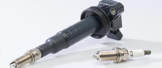
Purpose of the ignition coil on the VAZ 2107
The ignition coil is a key component of the machine, without which ignition of the air-fuel mixture in the combustion chambers is impossible.
The main device without which the VAZ 2107 will not start is the ignition coil
The standard voltage of the VAZ 2107 electrical network is 12 volts. The purpose of the ignition coil is to increase this tension to a level at which a spark will occur between the electrodes of the spark plugs, which will lead to ignition of the air-fuel mixture in the combustion chamber.
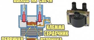
Ignition coil design
Almost all ignition coils on VAZ cars are conventional step-up transformers equipped with two windings - primary and secondary. Between them is a massive steel core. All this is placed in a metal case with insulation. The primary winding is made of copper wire coated with varnish insulation. The number of turns in it can vary from 130 to 150. It is this winding that is supplied with an initial voltage of 12 volts.
The design of the ignition coil on the VAZ 2107 cannot be called complex
The secondary winding is located on top of the primary. The number of turns in it can reach 25 thousand. The wire in the secondary winding is also copper, but its diameter is only 0.2 mm. The output voltage supplied to the spark plugs from the secondary winding reaches 35 thousand volts.
Types of ignition coils
Over the years, different types of ignition coils were installed on VAZ cars, which differed in design:
- common coil. One of the earliest devices that was installed on the very first G7s. Despite its venerable age, the coil is still installed on the VAZ 2107 today. The design of the device was described above: two copper windings on top of a steel core;
- individual reel. It is mainly installed on cars with electronic ignition systems. In these devices, the primary winding is also located inside the secondary, but individual coils are installed on all 4 VAZ 2107 spark plugs;
- twin coils. These devices are only used on vehicles with electronic ignition systems. These coils differ from all others in the presence of double wires, thanks to which the spark is supplied not to one, but to two combustion chambers at once.
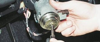
Location and connection diagram
The ignition coil on VAZ 2107 cars is located under the hood, near the left mudguard. Attached with two long studs. A rubber cap with a high-voltage wire is connected to it.
The coil is connected according to the diagram below.
The connection diagram for the VAZ 2107 ignition coil is not particularly complicated
Reel design and operation
The modern bobbin is a simplified version of the Ruhmkorff induction coil. It was named after the German-born inventor Heinrich Ruhmkorff, who was the first to patent a device in 1851 that converts low-voltage direct voltage into high-alternating voltage.
To understand the principle of operation, you need to know the structure of the ignition coil and the basics of radio electronics.
This is a traditional, common VAZ ignition coil, used for a long time and on many other cars. In fact, this is a pulse high-voltage transformer. On a core designed to enhance the magnetic field, a secondary winding is wound with a thin wire; it can contain up to thirty thousand turns of wire.
On top of the secondary winding is a primary winding made of thicker wire and with fewer turns (100-300).
The windings at one end are connected to each other, the second end of the primary is connected to the battery, the secondary winding with its free end is connected to the voltage distributor. The common point of the coil winding is connected to the voltage switch. This entire structure is covered by a protective housing.
A direct current flows through the “primary” in the initial state. When a spark needs to be formed, the circuit is broken by a switch or distributor. This leads to the formation of high voltage in the secondary winding. Voltage is supplied to the spark plug of the desired cylinder, where a spark is formed, causing combustion of the fuel mixture. High-voltage wires were used to connect the spark plugs to the distributor.
The single terminal design is not the only one possible; there are other options.
- Double spark. The dual system is used for cylinders that operate in the same phase. Let's assume that compression occurs in the first cylinder and a spark is needed for ignition, and in the fourth cylinder there is a purge phase and an idle spark is formed there.
- Three-spark. The principle of operation is the same as that of a two-terminal one, only similar ones are used on 6-cylinder engines.
- Individual. Each spark plug is equipped with its own ignition coil. In this case, the windings are swapped - the primary is located under the secondary.
About the choice of ignition coils for the VAZ 2107
The latest VAZ 2107 cars are equipped with contact ignition systems that use a domestically produced B117A coil. The device is quite reliable, but every part has its own service life. And when the B117A fails, it is quite difficult to find it on sale.
Standard coil VAZ 2107 - B117A
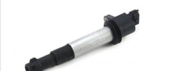
For this reason, motorists prefer to install a 27.3705 coil. It costs more (from 600 rubles). Such a high price is explained by the fact that the 27.3705 coil is filled with oil inside, and the magnetic circuit in it is of the open type. It is this device that is recommended to be used when replacing a burnt out coil.
Coil 27.3705 - oil-filled, with an open core
The third option should also be noted here: coil 3122.3705. There is no oil in this coil, and the magnetic circuit is closed. Despite this, it costs more than 27.3705 (from 700 rubles). Coil 3122.3705 is as reliable as 27.3705, but given its inflated price, most car owners opt for 27.3705. Foreign-made coils are not installed on the VAZ 2107.
Main malfunctions of VAZ 2107 ignition coils
If the driver, after turning the ignition key, clearly hears that the starter is rotating, but the car does not start, then most likely the ignition coil is faulty. It should also be noted here that the engine may not start for other reasons: due to problems with spark plugs, due to malfunctions in the fuel system, etc. You can understand that the problem is in the ignition coil by the following signs:
- there is no spark at the spark plugs;
- there is no voltage on high-voltage wires;
- Various defects are visible on the coil body: chips, cracks, melted insulation, etc.
- When you open the hood you can clearly smell the smell of burnt insulation.
All these signs indicate that the ignition coil has burned out. As a rule, this occurs due to a short circuit of the turns in one of the windings. The insulation that covers the wires in the winding deteriorates over time, adjacent turns become exposed, come into contact, and a fire occurs at the point of their contact. The winding melts and becomes completely unusable. For this reason, ignition coils cannot be repaired. All a car enthusiast with a burnt out coil can do is replace it.
Video: faulty ignition coil
Ignition system without runner
Installation of a four-terminal ignition coil (ignition module) from fuel-injected cars to carburetor cars.
A simple device for those who are tired of changing distributor caps and sliders. The efficiency of using these coils in the ignition system is much higher than classic ones, due to the reduction of losses when transmitting high voltage to the spark plugs. In a pair of slider and distributor cap, 30% of the spark energy is lost; there is no such deficiency in this system. Feel the effect immediately, in the form of improved engine performance, especially noticeable at idle speed. This circuit is a small add-on to the standard switch from a contactless ignition system, which can be soldered and started in a couple of hours.
L497 is an ignition controller located in a standard switch, the lower hall is standard, I took the upper hall with a built-in magnet, screwed it to the distributor cover approximately in the middle between the terminals and soldered a wire onto the slider, it turned out to be a phase sensor, who is too lazy to do this, they can screw a standard one from the injector .
A signal inverter from the sensor is made on the KT6116; it can be replaced with any low-power PNP structure. IRFZ44 transistors are parallel switches; they can be replaced with any other field switches with an insulated gate and low channel resistance, so as not to be hung on a radiator. The BU941 is a powerful composite transistor with built-in voltage protection, operating on the ignition coil, which can be replaced with the domestic KT898 (be sure to ensure good heat dissipation). The CD4047 chip is included in this circuit as a reset trigger; it can be replaced with our 561 series, for example K561TM2 in the corresponding connection.
The circuit works like this: the signal from the standard hall sensor comes to the fifth leg of the L497 chip, is processed there and from the fourteenth leg goes to the IRFZ44 parallel switches, one of them is opened by the CD4047b chip and then to the base of the switching transistor. Leg 3 of the CD4047 chip receives a signal from the same sensor and switches the transistors with each spark. The second hall is needed so that when starting the engine, the spark hits the desired cylinder, the signal from it resets the trigger to its original state, and then only confirms the choice of cylinders (it will run without it, it will only start every other time).
I placed the device in a standard switch with hinged mounting, and screwed the key transistors to the radiator. For those who will use two two-terminal coils instead of one four-terminal one, take exactly the same ones. This modernization of the ignition system cost me the cost of the coil and high-voltage wires to it, the remaining parts cost about 150 rubles.
Author: S.V. Tikhomirov (Pukhov). E-Mail: zasosu2009 [dog] ya.ru
Self-check of the ignition coil
To independently check the serviceability of the ignition coil, the car owner will need a household multimeter.
Test sequence
- The ignition coil is removed from the car. All wires are removed from it.
- Both contacts of the multimeter are connected to the primary winding of the coil. The winding resistance is measured. Example: at room temperature, the resistance of the primary winding on the B117A coil is 2.5 - 3.5 Ohms. The primary winding of coil 27.3705 at the same temperature should have a resistance of no more than 0.4 Ohm.
- Now the multimeter contacts are connected to the high-voltage outputs on the secondary winding. The secondary winding of the B117A coil at room temperature should have a resistance of 7 to 9 kOhm. The secondary winding of coil 27.3705 should have a resistance of 5 kOhm.
- If all of the above values are met, the ignition coil can be considered serviceable.