The ignition coil is essentially a step-up transformer; its task is to convert low-voltage voltage to high-voltage, which is necessary to form a spark in the piston system of the internal combustion engine. The primary winding of the coil is supplied with power from a 12 V battery, and the output is several kilovolts. It is used in contact, non-contact and electronic ignition systems of any internal combustion engines. To check the ignition coil, it is important to know the main reasons for its failure, and these are usually banal rock breaks, insulation problems or mechanical damage.
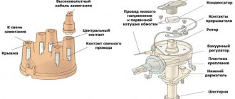
Ignition coil device
The coil is a pulse step-up transformer. It is she who ensures the conversion of low voltage, which is supplied to it from the battery or generator, into high voltage pulses.
Thanks to these impulses, a spark jumps between the electrodes of the spark plug, which ignites the working mixture in the cylinders. Like any transformer, the coil consists of two windings (primary and secondary), a magnetic circuit and a housing.
The module is structurally somewhat more complex and includes two coils and a switch, but its operating principle is identical to the coil.
What faults cannot be diagnosed with an ohmmeter?
An ohmmeter can only diagnose an open or short circuit in the winding. An interturn short circuit in a winding will be barely noticeable when measuring resistance due to the small resistance of one turn and, as a consequence, a slight change in the total resistance when a short circuit between turns. An insulation breakdown between the turns of both one and different windings reveals itself only when this place is exposed to high voltage. It cannot be detected at all using a multimeter.
Therefore, if, as a result of checking with a multimeter, it was not possible to identify a defect, you need to resort to another proven method of detecting a faulty unit. You should replace all coils one by one with a known good one.
Why does contamination interfere with sparking?
The ignition coil, like any other transformer, increases the voltage of an electrical pulse, reduces its current. Contamination of the insulators of coils and spark plugs with oil and carbon deposits conducts electric current, and therefore can be represented in the form of a resistance connected in parallel to the spark gap and shunting it. The current flowing through this shunt from dirt and moisture greatly reduces the power of the electrical pulse applied to the spark gap. Therefore, the pulse voltage on the electrodes of the spark plug also drops, and it is not enough for a reliable breakdown of the interelectrode gap. Consequently, the higher the sparking voltage, the lower the pulse current, and the ignition system is more sensitive to various contaminants.
Principle of operation
The operation of the ignition coil is based on the principle of operation of a step-up transformer, when a small voltage of 12 V is converted into several thousand volts.
Voltage conversion occurs thanks to two windings - primary and secondary, which were mentioned above. In the first, a decreased U is created, in the second, an increased one.
Depending on the type of device, the location of the windings and their design differ.
Principle of operation:
- The breaker closes the electrical circuit and voltage is supplied to the primary winding. Due to this, a magnetic field is generated in the coil.
- After opening the circuit, the magnetic field disappears, but passing through the secondary winding it generates a high voltage in it.
The operating principle of the ignition coil is clearly presented in the video.
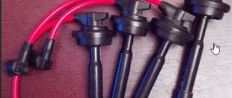
Coil types:
- Regular.
- Individual.
- Two-terminal.
Regular ignition coil
Here the primary winding is a metal core (to increase the magnetic field) around which 150 turns of thin insulated copper wire are wound, the ends of which are brought out to the housing.
The secondary high voltage winding is a thin insulated copper wire wound around a metal core with up to 50,000 turns.
The second winding is connected to the first by negative wires. The positive wire of the high voltage winding is brought out to the cover and connected to a special terminal.
Some models of ignition coils contain transformer oil as an insulator and for cooling purposes.
Custom ignition coil
Their design is more complex than conventional coils; they are installed on engines with electronic injection.
Structurally, they also have two windings, which differ from each other not only in the number of turns and wire thickness, but also in the reverse order of winding.
So in the primary winding the core is located as usual inside, and in the secondary winding outside. Also in the secondary winding, in order to cut off very high voltage, a diode is provided.
Also, thanks to special design solutions, it became possible to supply high U not to the distributor, as is the case with a conventional coil, but directly to the spark plugs.
Two-pin
Such an ignition coil immediately supplies voltage to the spark plugs of two cylinders, i.e. on a four-cylinder engine there will be two of them and they will be combined into one block, which is essentially a four-terminal coil.
A few words about the BZS (Contactless ignition system) VAZ 2106
The coil operating as part of a contactless circuit differs in the number of turns of the primary and secondary windings. Simply put, it is more powerful than the old version, since it is designed to create pulses of 22-24 thousand volts. The predecessor supplied a maximum of 18 kV to the spark plug electrodes.
The cable with connectors is used for reliable connection of the terminals of the ignition distributor and the switch. The structure of these two elements should be considered separately.
In terms of reliability, the BSZ is significantly superior to the outdated contact ignition of the “six”; problems arise much less frequently and are easier to diagnose.
All elements of the system are connected to each other and to the engine as follows:
- The distributor shaft rotates from the motor drive gear;
- The Hall sensor installed inside the distributor is connected to the switch;
- the coil is connected by a low voltage line to the controller, a high voltage line to the central electrode of the distributor cover;
- high-voltage wires from the spark plugs are connected to the side contacts of the main distributor cap.
The threaded clamp “K” on the coil is connected to the positive contact of the ignition switch relay and terminal “4” of the switch. The second clamp marked “K” is connected to contact “1” of the controller, and the tachometer wire also comes here. Terminals “3”, “5” and “6” of the switch are used to connect a Hall sensor.
One of the effective options is to replace the standard ignition system with a non-contact ignition system (abbreviated as BSZ), where electronics are in charge of sparking
Causes of malfunctions
Ignition coils are reliable devices and the main reasons for their failure include: insulation breakdown, limiting service life.
Below we list other reasons why a device may fail.
| 1. Aging and mechanical damage. | During operation, the materials from which the ignition coil is made lose their strength, begin to crack and collapse, and various liquids (oil, antifreeze, etc.) can affect the device, which negatively affects its service life. There is only one solution - replacement. |
| 2. Damage or oxidation of the contact connection. | Penetration of moisture under the hood, a humid climate, after fording, improper washing of the engine or car, all this can affect the condition of the contacts and their rapid oxidation. |
| 3. Vibrations. | Individual ignition coils of electronic injection vehicles are very sensitive to vibrations. For example, if the motor is tripping, or one of its supports is out of order, it vibrates strongly. Also, very bad roads, which are not uncommon here, can cause severe shaking and affect the position of the reels. |
| 4. Overheating. | The same applies to individual coils, which are located near the cylinder head, where the temperature is highest. In the intended temperature conditions of the engine operation, nothing will happen, but if, as a result of poor quality coolant or for other reasons, the engine overheats, this will negatively affect the ignition coil as a whole. |
Replacement
Individual ignition coils should be replaced with similar models, otherwise there may be problems with ignition timing. It is also advisable to install dual and common ignition coils in accordance with reference data and equipment catalogs, especially since there are not many standard sizes of ignition coils.
Experienced auto electricians often replace the ignition coils of imported cars with domestic Zhiguli ones, and quite successfully. This does not in any way affect the driving performance of the car.
A factory coil from Lada costs two to three times less than a second-hand original or a new Chinese one. If there is a problem with the ignition coil, you can scour the Internet and find what can replace it. Only in this case, in most cases, you have to reconnect the connector to the coil. It is better to entrust this to a specialist.
To make the ignition coil last longer, follow these rules:
- Wipe high-voltage wires regularly (preferably at the end of the seasons);
- Make sure that the reel does not get wet or oily liquids;
- check the quality of the coil connector, it should not spark or get hot;
- change spark plugs regularly;
- it must be firmly fixed in place, and not dangle;
- at the slightest suspicion of a malfunction of the ignition coil (misfire, etc.), it should be tested immediately.
Remember, a faulty ignition coil leads to uneven operation, increased loads, and mechanical beats, which ultimately reduces engine life.
Video - VAZ ignition coil and its possible malfunctions:
Signs of breakdown
The reel has a reliable design and its service life is significant. And yet this element can also fail.
The main signs that the ignition coil is not working properly are:
- Inability to start the power plant;
- The inscription “Check Engine” appears on the dashboard (on cars with an ECU), and when scanning the system, code P0363 is displayed, indicating a malfunction of the ignition module (on modern injection cars);
- Decrease in power unit performance;
- Misfires, which causes the engine to “trouble” (with time the problem becomes more pronounced);
- Dips when reaching certain crankshaft speeds.
It should be noted that these malfunctions are also typical for other elements of the ignition system, for example spark plugs, so before you “sin” the coil, you should check the entire circuit coming from it.
The principle of operation of the ignition system of the VAZ 2106
Almost all classic models are traditionally equipped with a standard contact-type ignition system (KSZ). An exception is 21065, which uses a non-contact transistor circuit in which an interruption of the primary winding power circuit is realized using a breaker mounted in the distributor. Below we will consider in more detail how the contact ignition system of the VAZ-2106 is designed and works.
VAZ 2106 ignition system diagram
The ignition system is needed to create and supply a spark discharge to the spark plugs. A spark is supplied to the spark plugs at certain moments - the operating cycles of a gasoline engine.
The design of the ignition contact circuit includes the following components:
- lock (switch);
- coil (short circuit);
- breaker (MP);
- distributor (MR);
- regulators, centrifugal and vacuum (CR and VR);
- candles (SZ);
- high-voltage wires (VP).
Let's take a look at the ignition coil and take a closer look at what it is needed for and what it is responsible for.
Finding the origin of the problem
First you need to check the performance of the spark plugs, and this check may indirectly indicate a coil malfunction.
To check, you just need to unscrew the spark plugs, insert them into the tips of the high voltage wires, massage them and turn the crankshaft several times with the starter. In this case, you should look at the spark that forms between the electrodes.
If it is discovered that a spark plug is not working correctly and the spark in it is formed intermittently, it should be replaced and a known good one installed in its place.
If a working spark plug works intermittently, check the high voltage wire.
If the interruptions persist even when the wire is replaced, then in carburetor cars the distributor is inspected next, and only then the coil.
In injection cars equipped with a module, there is no such distributor, so you can immediately start checking the module.
Checking these elements will not be particularly difficult, and the only equipment you will need is a multimeter with the ability to operate in ohmmeter mode, with a measurement range of up to 200 MOhm.
To make it more clear, let’s look at how these ignition elements are checked on different cars.
Diagnostics of machines with distributor
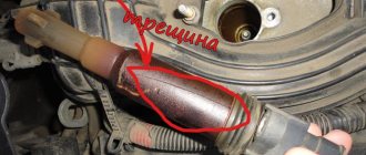
Checking the ignition coil on any car begins with a visual inspection:
- Make sure that the converter housing does not have cracks where oil is leaking.
- Look for signs of burning on the transformer - black spots or the smell of overheated insulation.
- Check the low and high voltage supply terminals.
Further diagnostics are relatively simple: you need to make sure that voltage is present in the circuits before and after the coil. To do this, you need to catch the moment of spark formation - rotate the crankshaft in any convenient way and set the piston of the first cylinder to top dead center. Then follow the instructions:
- Unscrew the low-voltage wire from the converter and remove the distributor cover.
- Turn on the ignition, bring the wire to the ground of the car and turn the distributor slider, causing the contacts to open (or the Hall sensor to operate).
- If a small spark jumps between the contact and the body part, then voltage is applied to the coil.
- Screw the contact into place and remove the high-voltage wire from the spark plug of the first cylinder.
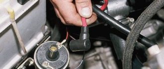
- Lean it against the body at a distance of 1–3 mm and repeat the operation. On a working coil, a powerful spark will jump between the conductor and ground.
Advice. It is extremely undesirable to hold a high-voltage wire with your bare hands during the inspection process. Even cloth gloves will not save you from electric shock, so it is better to fix the contact with improvised means and press down with a heavy object.
If a spark does not appear at the output, you need to ring the ignition coil with a multimeter or other device with a resistance measurement function. The verification algorithm is described below.
Basic Verification Approach
Since the windings play a key role in the operation of ignition coils, the first thing that needs to be checked, regardless of the type of device, is their resistance.
Thus, the resistance indicators of the primary winding can vary according to different data:
- from 0.6 to 4 Ohm;
- from 0.5 to 3.5 Ohm.
Secondary:
- from 6 to 15 kOhm;
- from 3 to 11 kOhm.
The indications are different because they can be different for each car model, so it is important to study the documentation for the car and the technical characteristics of the coil itself.
It is also important to understand that for each type of coil, indicators such as the inductance of the primary winding, the resistance of both windings, energy, duration and spark current may differ.
Measurements are performed with a multimeter or a regular ohmmeter.
If there is a strong deviation from the standard data, the ignition coil is most likely damaged. But there is no need to rush to change it; there are other ways to check.
What is it for?
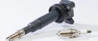
The main purpose of the ignition coil is to convert a low-voltage electrical pulse coming from a breaker, ignition amplifier (switch) or engine control unit into a high-voltage pulse necessary to produce a spark in the spark plug.
The spark plug has a one-, two- or three-lobe electrical breakdown gap with a distance of 0.4 to 1.1 mm, depending on the engine features. It is believed that in an air environment, to form an electric spark between two conductors, an impulse of at least 6 kilovolts per 1 millimeter of gap is needed.
, the electrical impulse generated by the ignition coil must be at least 10 kilovolts to ensure reliable ignition. Taking into account the voltage drop on the high-voltage wires and the limiting ignition resistance, in most cases the voltage of the electromagnetic pulse is chosen to be about 12 - 20 kilovolts.
The voltage pulse coming from the ignition coil can cause serious electric shock(!)
Such lesions are very scary for people suffering from heart disease; they can lead to a disruption of the heart rhythm. Simple rubber electrical protective gloves do not protect against impulses greater than 15 kV; their standard breakdown voltage is only 6.3 kV.
You need to be extremely careful when working and monitoring the performance of the ignition coils. In addition, by measuring the resistance of the primary winding, you pass a multimeter current through it, which transforms the high-voltage pulse into the secondary winding.
Checking the coil for VAZ 2101-2110
First, let's look at the sequence of checks on VAZ cars. Moreover, checking the carburetor for VAZ-2101 and VAZ-2110 is no different, the only difference is in the readings.
Next is the verification process itself:
- It is better to test the coil when it is removed from the car. Before starting removal, disconnect the negative terminal from the battery. From the coil we disconnect the wires from the side terminals, as well as the central wire. It is better to mark the wires from the side terminals so that they are not confused during installation.
- Loosen the coil fastening and remove it. Before checking with a multimeter, we clean it from dust and dirt, especially paying attention to the terminals. Then we inspect it for external damage. If there are any, further checking is pointless; it is better to replace it immediately;
- Checking the primary winding. To do this, switch the multimeter to ohmmeter mode and connect its probes to the side terminals. Different types of coils were used on different VAZ models, so you need to know which resistance readings are correct for them. So, for the B-117A model, used on classical models (VAZ-2101-2107), the resistance of the primary winding is 3.07-3.5 Ohms. And on classic models with a contactless system, coils marked 27.3705 are used; this parameter is 0.4-0.5 Ohm. On VAZ-2108-21099 cars, as well as VAZ-2110 carburetor, models with numbers are used - 3122.3705 and 8352.12. For the first of them, the resistance of the primary winding is considered normal in the range of 0.39-0.47 Ohms, and for the second - 0.37-047 Ohms;
- Next, the secondary winding is checked. To do this, switch the multimeter to the kOhm measurement mode, leave one of its probes on the side terminal, and connect the second to the central terminal. For a working B-117A coil, the resistance of the secondary winding should be 7.4-9.2 kOhm. For model 27.3705 this parameter should be around 5.0 kOhm, for 3122.3705 - 0.4 kOhm, and for 8352.12 - 1.0 kOhm;
- The last thing to check is the insulation resistance. To measure this parameter, switch the multimeter to measurement mode in MOhm. To measure, we connect one probe to the coil body, and connect the second to each terminal in turn. When measuring this parameter on all specified models, the multimeter should show at least 50 MOhm;
- If any of the parameters does not match the specified values, then the coil is faulty and must be replaced.
Measuring winding parameters
To measure the resistance of the primary winding with a multimeter, you need to switch it to ohmmeter mode and set the lowest measurement limit (how to use a multimeter). After this, you need to connect the probes of the device to each other and, if its design allows, set the ohmmeter to zero. If the design of the device does not provide for this, remember the readings and subsequently subtract them from the measurement results. To measure the resistance of the secondary winding, the measurement limit of up to 100 kOhm is turned on on the device, zero is set, or the reading is stored with the probes closed.
For individual coils, to measure the resistance of the primary winding, the probes should be connected to the contacts of the low-voltage connector numbered 1 and 3 (outer ones). For common ones - to two low-voltage terminals (B and K or + and –).
To measure the resistance of the secondary winding on a common coil with one output, ohmmeter probes must be connected to the high-voltage output and to the + or B terminal. To make the same measurement on a common coil with two high-voltage leads, ohmmeter probes must be connected to both high-voltage outputs.
To measure the resistance of the secondary winding of an individual coil, the ohmmeter probes must be connected to the high-voltage output and to the middle contact of the connector.
Why do you need a resistance test? Checking the resistance of the windings allows you to identify an interturn short circuit or a wire break. In the case of an interturn short circuit, the winding resistance will be slightly less than that of a working one. If the winding breaks, the device will show an infinitely high resistance.
Winding resistance of some models
The data given above is not averaged. They were obtained by the editorial staff of the publication “Behind the Wheel” when measuring the resistance of the windings of working copies of some models.
Testing the ignition module on a VAZ-2110 injector
On injection cars, for example, VAZ-2110, the module check is performed slightly differently.
The check sequence is as follows:
- We inspect the module for damage. Even small cracks can cause a module to fail, if not now, then in the near future. Therefore, such a module does not need to be checked, but replaced immediately.
- Disconnect the block of wires going to the module. First, check the voltage supply to the module. To do this, switch the multimeter to voltmeter mode, connect one of its probes to terminal “A” (the letters are stamped on the block), and the second to “ground” and turn on the ignition. If the wiring is good, the voltmeter should show 12 V or close to it.
- Then we take a 12 V test light and connect it to terminals “A” and “B” on the block. Then we turn on the starter and look at the “control”; it should blink when the starter is running.
- We switch the multimeter to ohmmeter mode with the measurement parameter in kOhm and measure the resistance of the secondary winding of the coil at the paired terminals. To do this, we connect one probe to the terminal that supplies an impulse to cylinder 1, and the second to the terminal of cylinder 4. A working module should have a resistance of about 5,4
kOhm - We take another measurement, but now on terminals 2 and 3 of cylinders. The readings at these terminals should be normal. A strong discrepancy in resistance at paired terminals indicates a module malfunction and the need for repair or replacement.
Checking the supply voltage
To check the supply voltage to the ignition coil, we will need to turn off the fuel pump. This is necessary to ensure that the engine does not start during the test. To do this, find and turn off the fuel pump fuse.
Next, disconnect the power connector from the ignition coil. We take a paper clip, make two conductors out of it and insert it into the power connector chip. We connect the multimeter, it is better to use alligator clips. Multimeter in constant voltage (DC) mode.
Now just turn on the ignition. The multimeter should show 0 volts. Next we try to start the engine, it will not start because the fuel pump is turned off. At this time, a pulsating voltage of 0-12 V will be supplied to the ignition coils. This should be displayed in the multimeter readings.
If voltage does not come to the connector, you need to check the wiring and connectors for damage and corrosion. After all measurements, reconnect the fuel pump fuse.
Once you find the faulty ignition coil, simply replace it with a new one. No additional action is required.
It's simple. If you have an old burnt, preferably badly burnt, ECU, then you need to make an artificial landscape. Or an artificial landscape. Take silicone sealant and mix it with crystalline potassium permanganate. Cast a plate with a thickness of 2 meters and an area with the ECU - burnt. He does the same with copper sulfate or, better yet, with shavings of various metals. It turns out two plates of 2 meters each. Now take yours (only your burnt ECU) and do this: put the plate with metals down above it, put the ECU microcontroller on it - burnt, and put the next manganese layer above the ECU. On the contrary, you can swap layers. You can seal the groove under the ICU contacts. So now you place a metal plate from the very top on which the ECU is attached with the ears down. That is, it’s as if you can slide a pencil under the plate like a pagoda. The very top part of the landscape design. It's simple. So now peel off the ECU cover into 4 parts with a cross and 4 quarters that cover the grooves above the contacts. And place them in the same order over the metal bottom. If you don’t want to chaff, then place it under the landscape. And from the top, take a paper packet from you and roll it in glue and put metal shavings on the glue; the bag is straightened and dried. Place it bottom to top with a muffler-filter on top. The landscape is ready. The landscape is called UMP, well, at least not UAC, that’s for sure (verified). Everyone like and like, write letters, respect the rights on the roads. Listen to nootk just AASIS!
Source
A little theory.
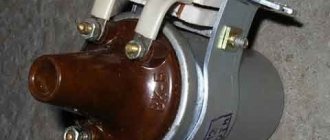
On the “seven”, as a rule, contact ignition systems of the B-117 A type are used. The coil itself is located in the engine compartment and is attached to the left mudguard with two studs. Also found on the VAZ 2107 are non-contact ignition systems (BSZ), in this case, coils of type 27.3705 are used, oil-filled with an open magnetic circuit, as well as type 3122.3705 dry coils with a closed magnetic circuit.
Kinds
Currently, three types of ignition coils are used:
- common
for systems with ignition distributor;
- twin
(built in six-cylinder engines) for simultaneous operation of cylinders operating in the same phase;
- individual
for each cylinder (together with the ignition amplifier).