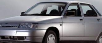
How to replace the steering column switch on a VAZ 2110
Replacing the steering column switch in a VAZ 2110 is carried out for the following reason: this element of the car is not as beautiful and functional as on foreign cars. On a VAZ 2110, replacing the steering column switch can be easily done on your own. You just need to follow the instructions and do everything in accordance with it.
Replacing the turn switch on a VAZ 2110
Note. On the VAZ 2110 you can easily and simply install switches from Lada Kalina, Chevrolet Niva or some foreign cars.
Features you need to know about
Replacing the steering column switch for a VAZ 2110
Let's look at some features of steering column switches from other cars that we want to install in the VAZ 2110:
- The main thing is the connector, which must match the VAZ 2110 and then there will be no problems.
- It is also recommended to pay special attention to the shape of the switch. For example, the steering column shifters from the Priora become further from the steering wheel than the tenth shift paddles. In this case, you have to lengthen the steering shaft or install another one from the same Kalina.
Steering column switches VAZ 2110
Note. There is another way: bend the steering column switch and cut off the excess part, and then glue it at a different angle, but this is not entirely correct. We need to think about safety, but a glued-on steering column does not fit in with this. Therefore, if we change the steering columns from Priora, Kalina or Niva, we will have to put up with a large distance of levers.
Conventional DIY installation of steering column stalks
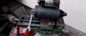
- Disconnect the positive wire from the battery.
- Now remove the lower steering column casing by unscrewing the 7 fastening screws.
- Lower the steering column down.
- Remove the upper steering column casing.
VAZ 2110 replacement of steering column switches
- We find two plastic clips and squeeze them to remove the windshield wiper switch (see Replacing windshield wipers on a VAZ 2110 on your own) from the base.
- Disconnect the block with wires.
- We now remove the turn signal and headlight switch, again, squeezing the two plastic clips.
We take a test lamp at 12 and connect it to the corresponding contacts:
Replacing steering column switches VAZ 2110
- If the lever is in the first position, then everything is turned off.
- If the lever is in the second or third position, then the numbers of closed contacts will be 49a-49aL and this is a left turn indicator.
- If the lever is in the fourth or fifth positions, then this is a right turn indicator and the numbers of closed contacts: 49a-49aR.
- If the lever is in the sixth position, then these are low beam headlights and the numbers of closed contacts: 56-56b.
- If in position seven, then this is a high beam alarm and the numbers of closed contacts are 30-56a.
- High beam is position eight and the contact numbers here are 56-56a.
Wiring diagram for fog lights.
According to the factory connection diagram, the fog lights turn on after the headlights are turned on. In this case, you can leave the headlights on with the engine off, which will drain the battery. To prevent this situation, it is better to connect the relay control wire to the terminal from the ignition switch (red in the diagram). But if you want to leave the switch on together with the dimensions, then pin 30 of the relay is best connected to a wire receiving power through the ignition switch. It should be taken into account that the load on the ignition switch will increase.
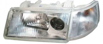
The car is equipped with two block headlights manufactured by Bosch or JSC Avtosvet, which combine low and high beam headlights, side (parking) light lamps and direction indicators. Headlight units vary in design. Low beam headlight "Avtosvet" - with a flat screen and a lens between the lamp and the lens, the lens of the headlight unit is glued to the body, the side light lamp is located in the main beam headlight. Bosch low beam headlight - without lens, with a screen cap on the lamp, side light lamp - in the low beam headlight. The turn indicators for both headlight units are the same, the mounting points are the same: at the top - with bolts to the upper cross member of the radiator frame, at the bottom - with a nut to the stud on the mudguard bracket and a bolt - to the radiator frame strut.
The headlights are equipped with single-filament low and high beam lamps. When you turn on the low beam of the headlights, the low beam lamps light up, and when you turn on the high beam, all the lamps (both low and high beam) come on.
The voltage for the low and high beam lamps is supplied respectively through relays K4 and K5 of type 904.3747-10, located in the mounting block. The relay switching voltage at a temperature of 20±5°C is no more than 8 V, the winding resistance is 85±8.5 Ohms. Voltage is supplied to the relay windings if the exterior lighting switch key is fully pressed (then the choice between low and high beams depends on the position of the headlight stalk switch) or - regardless of the switch position - if the driver pulls the steering column switch towards himself (then the high beam switches on headlights).
Hydrocorrector of headlights. Serves to change the angle of the headlights depending on the vehicle load. It consists of a master cylinder mounted on the instrument panel, slave cylinders mounted on the headlights, and connecting pipes. The cylinders and tubes are filled with a special liquid with a low freezing point and do not communicate with the atmosphere. The hydraulic corrector is non-removable and cannot be repaired. If the pistons in the cylinders become sour, there are leaks from the cylinders or tubes, and also if the stroke of the actuator rods (in headlights) differs from the value of 7±0.5 mm, replace the hydraulic corrector assembly.
Modification of the steering columns on the VAZ 2110
Refinement of the steering column switches
If the driver is not interested in the replacement process itself, but only needs to eliminate the clicks of the steering column switches, then we can advise you to simply carry out modifications.
Eliminating clicks
- We remove the switches from the VAZ 2110. Usually, no difficulties arise in this process.
- We disassemble the steering columns by snapping off the top cover with a screwdriver (small size).
- We find a small slide inside the switch (it is this that is responsible for the loud switching).
- Now you need to find a suitable rubber, for example, a car door seal (old and no longer needed). This very piece of rubber will need to be glued to the points of contact between the scenes.
Advice. To make the switching happen more smoothly, it is recommended to slightly file the plastic bump. We try to make the tip more rounded, otherwise it will jump. If this cannot be done, then you can use another method: weaken the spring.
- Let's put everything back together.
- We cover the switch body with some kind of vibration material. It is recommended to do the same with the steering shaft casing.
Closing the openings of the steering column switches
The openings can be closed easily and simply.
Sitting behind the wheel of a VAZ 2110, one cannot help but notice the large gaps located near the steering column switches. This looks very unaesthetic and not at all practical. Let's try to close them:
- Take a piece of black carpet.
- We cover the steering column switch with Moment glue.
- We wait until the required time dries.
- We glue the carpet directly onto the steering column switch, closing the gap.
Note. It is not necessary to use only carpet. If you don’t have it, then you can take a piece of modelin or even an old felt boot.
You can easily replace the switch yourself, following the instructions. Thus, it will be possible to save the price of services in specialized workshops. During the work process, it is recommended to study photo and video materials.
Wipers VAZ 2107
The vehicle is operated in different climatic and road conditions. For safe and comfortable movement, the driver must have good visibility of the road situation, i.e. the windshield must always be clean. Windshield wipers provide mechanical cleaning of the windshield from dirt and sediment, improving visibility and increasing safety. We will consider possible problems with this mechanism and ways to eliminate them in more detail.
Principle of operation
The work of the wipers is quite simple and consists of the following sequence of actions:
- The driver selects the desired operating mode of the windshield wipers using the steering column switch.
- The entire windshield cleaning mechanism is driven by a motor.
- The wipers move across the glass left and right at the selected speed, cleaning the surface.
- When the mechanism is no longer needed, the steering column switch returns to its original position.
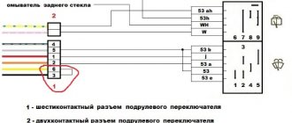
Wiring diagram for the wipers and windshield washer of the VAZ 2107: 1 - thermo-bimetallic fuse; 2 — windshield wiper gearmotor; 3 — electric motor for windshield washer; 4 — mounting block; 5 — washer switch in the three-lever switch; 6 — wiper switch in a three-lever switch; 7 — windshield wiper relay; 8 — ignition switch;
Components
The windshield wiper consists of the following main elements:
- lever mechanism (trapezoid);
- electric motor;
- relay;
- brushes
Trapezoid
One of the important elements in the windshield wiper mechanism is the trapezoid. On almost all cars this part is the same, and the difference lies only in the methods of fastening, the size and shape of the elements. The functioning of the trapezoid consists of transmitting rotational motion from the electric motor to the wipers, as well as ensuring the synchronous movement of the latter for high-quality glass cleaning. The trapezoid consists of rods, a body and a hinge.
Trapezoid design: 1 - crank; 2 - short thrust; 3 — joint of rods; 4 — rollers of the windshield wiper mechanism; 5 - long pull
Motor
The electric motor of the windshield wipers of the VAZ “Seven” is made as a single unit with a gearbox and is one of the main links of the mechanism in question. The motor consists of a stator with permanent magnets and an armature with an elongated shaft, at the end of which a screw is threaded. The purpose of this unit is to ensure the movement of the blades along the windshield. The device is considered reliable and fails very rarely.
Wiper relay
On classic Zhiguli cars, the windshield wiper has two operating modes - fast and intermittent with an interval of 4-6 seconds. It is to ensure intermittent operation that the RS 514 breaker relay is designed. Delayed activation of the wipers is used during light rain, when too frequent operation of the windshield wipers is not required, and when the mechanism is completely turned off, the glass is gradually covered with small drops of precipitation and needs to be cleaned. The product is connected to the general wiring using a four-pin connector. On the VAZ 2107, the breaker relay is located on the driver’s side on the left side panel under the plastic trim.
The wiper relay ensures intermittent operation of the mechanism
Brushes
Almost all passenger cars use two windshield wiper blades. On the “seven”, elements with a length of 33 cm are installed from the factory. Longer brushes can be installed, but a greater load will be placed on the electric motor, which will lead not only to slower operation of the mechanism, but also to possible failure of the motor.
The VAZ 2107 is equipped with brushes 33 cm long from the factory.
Why the wipers don't work
At some point, the car owner may notice that his wipers are not working. This may manifest itself in their complete stop or creaking operation.
Trapezoid Compatibility
First of all, look for the reason in the electric motor. But remember that mechanical problems also happen.
The most popular mechanical breakdowns of wipers:
- When the cleaners turn on, the sound of the motor is heard, but the brushes do not move or twitch slightly. Most likely, the nut securing the crank to the gearbox axle has lost its grip or has become completely unscrewed.
- Non-synchronous operation of the windshield wipers indicates a problem with the drive. Again, check the locking nut. When tightening the nut, be sure to first place the brushes in the correct position.
Article on the topic: Replacing the rear and front struts of a VAZ 2110. Which struts are better to install?
As for problems with the electrical component, they manifest themselves as follows:
- The wiper moves very slowly, stops, then starts working again, does not stubbornly go to the lower position. Check the limit switch. By bending the contacts, it is adjusted in this way. If such a measure does not bear fruit, replace the entire VAZ 2110 wiper motor assembly, since the gearbox is built-in;
- You have turned on the intermittent mode, but the brushes work non-stop. Here the problem lies in the relay, which needs to be replaced. If when you turn on the device you do not hear a sound from the rotation of the motor armature, then the relay is 100% to blame. If not, then check for burns and oxidation on the contacts;
- When choosing any mode, you can only hear the clicking of the thermometallic fuse. At the same time, the anchor and brushes remain in place. Check to see if the brushes are frozen because of the frost and that’s why they don’t move. Either fuse F5 has blown, or the armature has burned out;
- The electric motor does not turn on, although the fuses are good. Check the quality of contacts. This often causes a stuck brush or a burnt armature.
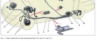
Exterior lighting, brake and reverse lights, interior and trunk lighting
The front side light lamps are located in the headlights (see the “Headlights” section), the rear lamps are located in the external rear lights (on the car’s fenders). The brake and reverse lamps are located in the inner rear lights on the trunk lid. (Removing the brake light switch, see “Removing the vacuum booster and brake pedal assembly”). The license plate lights are located on the bumper.
The parking light is on when the exterior light switch is pressed. The side light and brake light lamps are powered through relay K1 for monitoring the health of the lamps in the mounting block. If any of the lamps burns out or the contact in the socket or supply circuit is broken, the corresponding indicator lights up in the control unit. If there is no lamp control relay, there must be jumpers instead, otherwise the lamps will not light.
The license plate lamps turn on simultaneously with the exterior lighting, but are connected bypassing the control relay, so their serviceability is not diagnosed.
The glove box illumination lamp is turned on when the ignition is turned on by a switch under the box lid.
Voltage is also supplied to the switches of the interior courtesy lamp lamps and the driver's individual courtesy lamp when the ignition is turned on. In addition, the interior lamp lights up if one of the doors is open and the courtesy light switch is in the appropriate position. A few seconds after closing the door, the brightness of the lamp decreases and it goes out. This is controlled by the display unit of the on-board control system.
The instrument lighting turns on simultaneously with the exterior lighting. The brightness of the backlights is controlled by a rheostat on the instrument panel.
The reverse lamps come on when the ignition is turned on and the reverse switch located on the transmission is closed.
The trunk lighting turns on simultaneously with the side light lamps.
Checking and replacing steering column switches on a VAZ 2110 Lada
/ VAZ/ vaz-2110/ Electrical equipment/ Lighting, light and sound alarms/ Checking and replacing steering column switches
7.8.7. Checking and replacing steering column switches
Turn signal and headlight switch type 69.3709
Windshield wiper and washer switch type 70.3709
Steering column switch lever positions
* Non-fixed position. Contact closure at different positions of the windshield wiper and washer switch lever
| Lever position | Numbers of closed contacts | Switched devices |
| I | – | Everything is off |
| II | 53e–53, 53a–j | Intermittent wiper operation* |
| III | 53e–53, 53a–j | Intermittent wiper operation |
| IV | 53a–53 | First wiper speed |
| V | 53a–53b | Second speed wiper |
| VI | 53ah–W | Washer and wiper* |
Comments
Leave a comment Cancel reply
Repair of Largus steering column switch
This car came to us with a common problem in Largus.
Even though it’s not a Solaris, they helped. Having done the diagnostics, we found a fault - the steering column switch. After removing it we saw the problem. On the rod, which is located inside the handle, the wires came off, because the design there... is so-so =(
There was no time for photos here. I wrapped the "end" of the handle in duct tape to prevent damage and removed it using plastic pullers and a lot of force and anger.
Ready. We collect and enjoy the signal =))
Thank you all for your attention. I hope this information is useful to someone.
The steering column switches on the Lada Largus car perform a number of switching functions in the electrical circuits of the car. If the switches are faulty, you may not be able to fully use the lighting, turn signals, wipers, horn, etc. In this article we will talk about removing the switches in case of replacing them, and also provide a table with the closed contacts of the steering column switches when operating them.
conclusions
As practice shows, it is not difficult to dismantle and disassemble the headlight on a VAZ-2110. Difficulties may arise during assembly, and especially when gluing glass and body. Otherwise, there shouldn't be any special problems.
A properly working VAZ-2110 turn signal is used to inform other road users about the planned direction. That is why any malfunctions of the indicator must be eliminated as soon as possible.
First of all, the problem will attract the attention of traffic police officers, who will impose a fine for non-working VAZ turn signals. Before you go to the store to buy the necessary part, you need to correctly determine the cause of the malfunction.
Connecting the trip computer
The mentioned diagram took into account only one, brown wire leading from the red block to the trip computer, but this is clearly not enough. Therefore, let's see how the pinout occurs here.
- The fuel consumption signal from the electronic control unit is indicated by a green wire;
- Orange leads to terminal “15” in the ignition switch;
- Red and white - to terminal “30” in the ignition switch;
- Black, which is common, goes to ground;
- The speed indicator corresponds to brown;
- The positive terminal of the fuel sensor is green and red;
- Responsible for lighting the dashboard white, it leads to the light control.
Make sure that the board is not damaged, on which, in fact, uninterrupted reading of information from your VAZ 2110 depends, and providing it to you through all those sensors and devices that you always see in front of you.
Turn signal lamp
200501-
Front Voltage: 12
Rated power:
21
PY21W Cartridge version:
BAU15s
Search
200501 - side mounting
Voltage : 12
Rated power:
5
W5W Cartridge version:
W2.1×9.5d
Search
200501- rear
Front Voltage: 12
Rated power:
21
P21W Cartridge version:
BA15s
Search
200501 - side mounting
Voltage : 12
Rated power:
5
W5W Cartridge version:
W2.1×9.5d
Search
200501-
Front Voltage: 12
Rated power:
21
PY21W Cartridge version:
BAU15s
Search
200501- rear
Front Voltage: 12
Rated power:
21
P21W Cartridge version:
BA15s
Search
200501 - side mounting
Voltage : 12
Rated power:
5
W5W Cartridge version:
W2.1×9.5d
Search
200501- rear
Voltage : 12
Rated power:
21
P21W Cartridge version:
BA15s
Search
200501-
Front Voltage: 12
Rated power:
21
PY21W Cartridge version:
BAU15s
Search
200501 - side mounting
Voltage : 12
Rated power:
5
W5W Cartridge version:
W2.1×9.5d
Search
side mounting
Voltage : 12
Rated power:
21
Cartridge version:
BA15s
transparent
Search
side mounting
Voltage : 12
Rated power:
21
Cartridge version:
BAU15s
yellow
Search
side mounting
Voltage : 12
Rated power:
5
Cartridge version:
W2.1×9.5d
yellow, transparent
Search
behind
P21W Voltage: 12
Rated power:
21
Quantity:
10
Cartridge design:
BA15s
front and rear Box
Search
P21W Voltage: 12
Rated power:
21
Quantity:
2
front and back blister pack Cartridge version:
BAY15s
Search
P21W Voltage: 12
Rated power:
21
Quantity:
2
Cartridge version:
BA15s
front and back blister pack Search
P21W Voltage: 12
Rated power:
21
Quantity:
10
Cartridge design:
BAY15s
front and rear Box Search
P21W Voltage: 12
Rated power:
21
Cartridge version:
BA15d
front and rear Quantity:
10
Box Search
front
PY21W Voltage: 12
Rated power:
21
Quantity:
10
Cartridge design:
BAU15s
front and rear Box
Search
PY21W Voltage: 12
Rated power:
21
Cartridge version:
BAU15s
front and rear Quantity:
2
blister pack Search
PY21W Voltage: 12
Rated power:
21
Quantity:
2
Cartridge version:
BAU15d
front and back blister pack Search
side mounting
WY5W Voltage: 12
Rated power:
5
Quantity:
10
Cartridge design:
W2.1×9.5d
front and rear Box
Search
WY5W Voltage: 12
Rated power:
5
Cartridge version:
W2.1×9.5d
front and rear Quantity:
2
blister pack Search
behind
P21W Voltage: 12
Rated power:
21
Cartridge version:
BA15s
Search
front
PY21W Voltage: 12
Rated power:
21
Cartridge version:
BAU15s
Search
behind
P21W Voltage: 12
Rated power:
21
Cartridge version:
BA15s
blister pack Quantity:
2
Search
front
PY21W Voltage: 12
Rated power:
21
Cartridge version:
BAU15s
blister pack Quantity:
2
Search
side mounting
WY5W Voltage: 12
Rated power:
5
Cartridge design:
W2.1×9.5
blister pack Quantity:
2
Search
behind
P21W Voltage: 12
Rated power:
21
Cartridge version:
BA15s
Search
front
PY21W Voltage: 12
Rated power:
21
Cartridge version:
BAU15s
Search
side mounting
WY5W Voltage: 12
Rated power:
5
Cartridge version:
W2.1×9.5
Search
front
Voltage : 12
Rated power:
21
PY21W Cartridge version:
BAU15S
external orange
Search
Steering columns from Kalina, Priora and Chevy Niva
Note. On the VAZ 2110 you can easily and simply install switches from Lada Kalina, Chevrolet Niva or some foreign cars.
Features you need to know about
Replacing the steering column switch for a VAZ 2110
Let's look at some features of steering column switches from other cars that we want to install in the VAZ 2110:
- The main thing is the connector, which must match the VAZ 2110 and then there will be no problems.
- It is also recommended to pay special attention to the shape of the switch. For example, the steering column shifters from the Priora become further from the steering wheel than the tenth shift paddles. In this case, you have to lengthen the steering shaft or install another one from the same Kalina.
Steering column switches VAZ 2110
Note. There is another way: bend the steering column switch and cut off the excess part, and then glue it at a different angle, but this is not entirely correct. We need to think about safety, but a glued-on steering column does not fit in with this. Therefore, if we change the steering columns from Priora, Kalina or Niva, we will have to put up with a large distance of levers.
Conventional DIY installation of steering column stalks
- Disconnect the positive wire from the battery.
- Now remove the lower steering column casing by unscrewing the 7 fastening screws.
- Lower the steering column down.
- Remove the upper steering column casing.
VAZ 2110 replacement of steering column switches
- We find two plastic clips and squeeze them to remove the windshield wiper switch (see Replacing windshield wipers on a VAZ 2110 on your own) from the base.
- Disconnect the block with wires.
- We now remove the turn signal and headlight switch, again, squeezing the two plastic clips.
We take a test lamp at 12 and connect it to the corresponding contacts:
Replacing steering column switches VAZ 2110
- If the lever is in the first position, then everything is turned off.
- If the lever is in the second or third position, then the numbers of closed contacts will be 49a-49aL and this is a left turn indicator.
- If the lever is in the fourth or fifth positions, then this is a right turn indicator and the numbers of closed contacts: 49a-49aR.
- If the lever is in the sixth position, then these are low beam headlights and the numbers of closed contacts: 56-56b.
- If in position seven, then this is a high beam alarm and the numbers of closed contacts are 30-56a.
- High beam is position eight and the contact numbers here are 56-56a.
Connector for the steering column of Priora, Grant, Kalina-2 of a new type for an airbag (since 2011)
The steering column switch is designed to quickly turn on (off) the turn signal, low or high beams, windshield wipers with adjustable speed, side lights, and windshield washer.
Each function is performed by closing a separate circuit with the switch paddles located under the steering wheel. The classic option was the presence of two or three switches. The cable that controls the lighting and turn signals has the following positions:
- lights are completely turned off;
- low beam works;
- high beam is on;
- high beam operation (non-fixed position, valid regardless of the type of lighting turned on);
- right turn;
- left turn.
The switch that controls the windshield wiper and washer has the following positions:
- everything is disabled;
- intermittent operation of windshield wipers;
- the first speed of the purifier in constant mode;
- second speed in constant mode;
- simultaneous operation of the windshield wiper and washer (non-fixed position).
If there is a rear window wiper, there are additional positions on the steering column for its control.
Malfunctions of the steering column connector
The basic design of the switch is extremely simple, which ensures its durability. At the same time, careless use can lead to failure of the switch. A sign of this is the impossibility of including one or more provisions.
To carry out diagnostics, it is necessary to determine the integrity of the circuit between the contacts in order to exclude the presence of a malfunction outside the steering column loop. To do this, just remove the connector and use a regular tester for control (you can use a 12 V light bulb and a current source), having previously closed the desired pair of contacts with a switch.
Another cause of the malfunction is oxidation of the contacts, which does not allow closing the electrical control circuit (the most pressing problem is for cars that are used only in the summer, and in the winter they are parked in rooms with high humidity or outside). In the second case, the problem is solved by simple cleaning followed by integrity monitoring. If the problem is in the circuit of the steering column switch itself, then it will need to be removed and completely disassembled to find the problem.
Practice shows that often repairing the steering column connector for Lada Priora, Kalina and other VAZ models does not make sense due to the affordable cost of the cable itself. Also, the design of the switch itself is made in a non-disassembled form, which requires drilling out rivets and solving a lot of issues that arise during assembly.
How to remove the steering column switch?
It is better to test the condition of the cable in the removed position. You can do this yourself using the following algorithm:
- remove the battery terminal to prevent electric shock;
- Using a screwdriver, unscrew 4 screws (2 on top and 2 on bottom) next to the steering wheel, which connect the two steering column casings;
- unscrew the self-tapping screw that secures the lower casing to the steering column switch;
- unscrew the two self-tapping screws located in the steering column bracket;
- dismantle the casings and disconnect the cable connector;
- squeezing the two clips, remove the connector itself from each side.
If you need to further check or replace the switch connector, you need to remove the steering wheel itself and disconnect the horn power wires. Assembly is carried out in reverse order.
Removing and installing the steering column switch
| GENERAL INFORMATION |
PERFORMANCE ORDER 1. Disconnect the negative cable (–) of the battery with the ignition off. ATTENTION As a result, information from the electronic memory units, such as the radio code, is erased. Without a code, the radio can only be turned on by the manufacturer or an AUDI service station. Therefore, read the materials in the subsection Entering the radio code. Be sure to read the notes on safety precautions when using the airbag, and refer to the Steering subsection.
2. Remove the airbag unit from the driver's side, and refer to the subsection Removing and installing the airbag unit. 3. Remove the steering wheel, and refer to the subsection Removing and installing the steering wheel.
4. Disconnect the handle of the steering column adjustment mechanism –1–.
5. Remove the 2 Phillips screws –4– and the Allen screw –2– (4 mm wrench). 6. Remove the 2 fastening screws –3– with a thin long screwdriver. 7. Remove the upper and lower parts of the steering column switch trim.
8. Unplug connector –1–.
9. Remove the –2– (5 mm) hexagon socket screw so that the steering column switch can move slightly. 10
Carefully disconnect the electrical connections from the steering column switch. ATTENTION When removing the steering column switch, the spring remains on the switch
Make sure that the spring does not twist and remains in its middle position.
11. Remove the steering column switch from the column and place it to the side.
1. Place the steering column switch –2– on the steering column without securing it.
2. Put on the steering wheel. 3. First secure the steering column switch -2- with a hexagon socket screw -3- on the steering column so that the distance to the steering wheel is a = 3 mm. 4. Remove the steering wheel again and perform further installation in the reverse order of removal. 5. Install the steering wheel, refer to the subsection Removing and installing the steering wheel. 6. Install the airbag, refer to the subsection Removing and installing the airbag unit. 7. Connect the ground cable (–) of the battery
Attention: Activate the high-altitude automatic power window, as well as set the clock and enter the radio code, refer to the subsection Entering the radio code
Article: 2123.3709.330, additional articles: 2123-3709330
Order code: 029589
- Buy with this product
- show more
Steering light switch 2123-3709330
Rated voltage - 12 V Switching current - 8 A Applicability
: cars VAZ-2123, VAZ-2170, VAZ-1118
Passenger cars / VAZ / Lada Kalina 11181 drawing
» href=»/catalog/vaz-3/legkovye_avtomobili-30/lada_kalina_1118-437/signaly-143/#part1358097″>Light alarm switchElectrical equipment / Signals
- Passenger cars / VAZ / Lada Kalina 1117, 1118, 11191 drawing
- » href=»/catalog/vaz-3/legkovye_avtomobili-30/lada_kalina_1117__1118__1119-1048/signaly-186/#part2613767″>Light alarm switchElectrical equipment / Signals
- Passenger cars / VAZ / Lada Kalina 1119 Sport1 drawing
Read also: Eyelashes opel astra h - » href=»/catalog/vaz-3/legkovye_avtomobili-30/lada_kalina_1119_sport-1556/signaly-132/#part3440285″>Light alarm switchSignals, devices, relays / Signals
- Passenger cars / VAZ / Lada Priora 21728 Coupe1 drawing
- » href=»/catalog/vaz-3/legkovye_avtomobili-30/lada_priora_21728_coupe-1878/signaly-163/#part4191137″>Light alarm switchInstruments and sensors / Signals
- Passenger cars / VAZ / Lada Priora 2170 FL1 drawing
- » href=»/catalog/vaz-3/legkovye_avtomobili-30/lada_priora_2170__fl-1889/k300__signaly-245/#part4225497″>Light alarm switchSignals, devices, relays / K300. Signals
- Passenger cars / VAZ / VAZ-21231 drawing
- » href=»/catalog/vaz-3/legkovye_avtomobili-30/vaz_2123-315/signaly-202/#part978971″>Light alarm switchElectrical equipment / Signals
- Passenger cars / VAZ / Lada Priora 21701 drawing
- » href=»/catalog/vaz-3/legkovye_avtomobili-30/lada_priora_2170-480/signaly-164/#part1580008″>Light alarm switchElectrical equipment / Signals
- Passenger cars / VAZ / Lada Granta 21901 drawing
- » href=»/catalog/vaz-3/legkovye_avtomobili-30/lada_granta_2190-1236/signaly-162/#part2982118″>Light alarm switchElectrical equipment / Signals
- Passenger cars / VAZ / Lada Kalina 2192, 21944 drawings
- » href=»/catalog/vaz-3/legkovye_avtomobili-30/lada_kalina_2192__2194-1646/signaly-154/#part3654086″>Light alarm switchSignals, devices, relays / Signals
- » href=»/catalog/vaz-3/legkovye_avtomobili-30/lada_kalina_2192__2194-1646/signaly-153/#part3654058″>Light alarm switchSignals, devices, relays / Signals
- » href=»/catalog/vaz-3/legkovye_avtomobili-30/lada_kalina_2192__2194-1646/signaly-154/#part3654085″>Light alarm switchSignals, devices, relays / Signals
- » href=»/catalog/vaz-3/legkovye_avtomobili-30/lada_kalina_2192__2194-1646/signaly-153/#part3654059″>Light alarm switchSignals, devices, relays / Signals
- Passenger cars / VAZ / Lada Kalina 21942 drawings
- » href=»/catalog/vaz-3/legkovye_avtomobili-30/lada_kalina_2194-1886/k300__signaly-229/#part4211706″>Light alarm switchSignals, devices, relays / K300. Signals
- » href=»/catalog/vaz-3/legkovye_avtomobili-30/lada_kalina_2194-1886/k301__signaly-230/#part4211731″>Light alarm switchSignals, devices, relays / K301. Signals
- Passenger cars / Chevrolet / Chevrolet Niva 1.71 drawing
- » href=»/catalog/chevrolet-125/legkovye_avtomobili-30/chevrolet_niva_1_7-1233/signaly-235/#part2975610″>Light alarm switchElectrical equipment / Signals
There are no reviews for this product yet.
The series of articles “Crystal VAZs, or typical breakdowns of domestic cars” talks about typical problems and malfunctions of cars produced by the Volzhsky Automobile Plant. Today we will talk about the front-wheel drive Samara family, as well as its modern analogues.
Do-it-yourself modification of the VAZ 2110 steering column switches
We show how to replace the steering column switches in VAZ 2110, 2111, 21112 cars. The steering column switches are responsible for the operation of the wipers, turn signal indicator, high beam, and washer fluid supply. What problems might arise with them? Personally, while owning a car of the tenth family, I encountered such a problem: when driving without low beam, the high beam could automatically turn on. I constantly had to hold the switch so that it did not turn on spontaneously.
First of all, you need to unscrew the bolts of the steering casing, move the steering wheel adjustment lever down and remove the lower casing, it is advisable to remove the upper one. Now we can clearly see our steering column switches, they are attached to two latches, you can replace them with new ones using two fingers, you don’t have to unscrew anything:
Video of replacing steering column switches in VAZ 2110 2111 2112:
Priora GM
Let's begin! So we need: 1) Straight arms 2) GM steering column switches 3) Insert into helicopter 2108 4) wire 5) small and large male and female males 6) heat shrinkage 7) a pair of relays
relay pads 9) time
Well, now about the hands. knowledge of car electronics and hands growing from the right place is a must, otherwise a fire or something else is possible!
We go to the Korean spare parts store and buy left and right steering column switches (I took them from the Lacetti), then either use ours or buy a new helicopter insert 2108!
We use any wire you like!
dads moms small and large, you can use electrical tape instead of heat shrink, but I don’t recommend it!
The original chips were cut off because I couldn’t find the original matching parts, both from the left and right switch!
Let's start with small chips: Left (turn signals-light) 1) Black - general 2) White - clearance 3) Green-black - low beam 4) Yellow - PTF 5) Red-yellow - PTF So what do we have, but we have a difference from switching circuits from the VAZ, since on the VAZ the power supply is low current and the size is divided into dimensions + it weighs constantly and for low current, after turning on the ignition, we will correct this matter with the help of a relay! It would also be advisable to hang a relay on the dimensions, since the output on the switch is low-current, but on the VAZ there are no relays and the entire load from the dimensions falls on the button! PTF can be hung here if desired + permanent can be from the dimensions or from the ignition, I will hang from the ignition!
Steering wheel paddle shifters for manual transmission
Until recently, paddle shifters were only installed on automatic transmissions. But the designers of Master Shift from the United States demonstrated an innovative and quite promising concept in this direction at the auto show in Las Vegas. Their invention makes it possible to replace a manual transmission with a system with steering wheel paddle shifters. Three pedals remain in the car, but the traditional manual transmission stick is not used. The drive unit and the box are connected via adapters. Under the clutch pedal there is a special sensor that detects the release of the discs, and then using the paddle, the required gear is selected. After depressing the clutch pedal, the discs are separated, the electric drive supplies the required stage and the discs are closed.
The designers installed special systems that block the electric drive when selecting reverse speed if the car is moving forward.
It is likely that in the near future cars equipped with such a gear shift system will be mass-produced.
In new foreign cars you can see small levers on the steering wheel, they are called steering wheel paddles. In the overall picture of the interior, they look cool, modern, and many people like this design. But these petals are created not only to style modern cars. What else is it for? We will discuss this with you now.
What are they and how did they appear?
Steering wheel paddle shifters are two levers that can be pressed to change gears.
Steering wheel paddles were invented in the eighties of the last century and were first installed on Ferrari and Porsche, and then on other Formula 1 sports cars. And they created such an ultra-fashionable device for changing speed without taking the driver’s hands off the steering wheel. We decided that this would be very convenient for racing car drivers - now they did not need to look at the gearbox. And in the modern world, they are increasingly beginning to appear on ordinary cars with electronics.
Design and principle of operation
The paddle shifters are mounted on the steering column, right under the steering wheel - hence the name.
When you press the paddle, the signal is transmitted to the gearbox control unit, and then the automatic system selects the desired gear. Activation of the paddles occurs in two ways: in some cars they are always active, while in others you need to select the manual gear shift mode, and they become active.
If the driver does not use them for a long time, the car switches to an automatic transmission. It depends on the car brand. The main thing is to be able to choose the right moment to change gear, and the switching is already carried out by the computer.
Advantages and disadvantages
The very first and biggest advantage is what the paddles were created for - convenience and speed of gear shifting. You no longer need to lift your hand from the steering wheel and pull the large gearshift lever, just press the paddle with one finger. Because this very petal is right at your fingertips. This is especially convenient when driving fast, for example, abruptly shifting gears while overtaking another car. And also when you need to quickly accelerate.