The green control wire from terminal 85 is brought into the interior; drilling of the engine shield is allowed. In this case, the installation of PTF usually does not require separate preparation of the installation site, since the fog lamps are placed in ready-made places, covered with plugs.
If there is no free button on the instrument panel, you will have to mount it in a convenient place. We also recommend reading the article on how to connect a radio with your own hands. The benefit from such illumination is zero, but such a technique will be fully blinding. how to connect a car relay (light ignition, etc.)
Pairs of terminals and interchangeable.
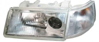
When using non-original headlights, there may be discrepancies in dimensions and mounting points.
Some fans of SUVs mount additional lights at the level with standard optics or on the roof of the car.
This technique eliminates the possibility that the driver may forget to turn off the PTF on his own. Volgograd region Available with low beams, running lights or fog lights. PTF Priora COMPLETE INSTALLATION of wiring, connection to the ignition system
Connection diagram for DRL via 5-pin relay
This scheme is the most correct and automated; I recommend connecting the DRLs according to this scheme. This circuit uses a 5-pin relay. Let's talk a little about the operating principle of a 5-pin relay. The 5-pin relay has 2 power outputs. In the normal state, the first of the power terminals is closed, the second is open. After applying a control signal to the relay, the first output will become open and the second will become closed. This seems complicated, but let's look at an example and everything will become clear.
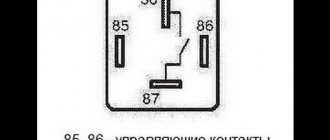
- Contacts 85 and 86 are control contacts. Depending on whether there is voltage on them or not, contacts 87 or 87A close;
- Contact 30 – power supply contact of the relay. It is to this that voltage must be supplied to power consumers;
- Contacts 87 and 87A – contacts for connecting consumers.
Let me give you an example. There is no voltage on contacts 85 and 86; power through the relay goes to the consumer at contact 87A. There is voltage on pins 85 and 86, the relay switches power to the consumer on pin 87.
- We supply power to the DRLs and headlights through pin 30. For greater automation, take power from the main circuit of the car, which turns on when the ignition is turned on;
- We connect DRLs to contact 87A, which will always be on;
- We connect the headlights to pin 87, which will turn on only when the DRLs are turned off;
- To contacts 85 or 86 (it doesn’t matter), we apply a control signal from the headlights button in the cabin;
- We connect the remaining contact 85 or 86 to the car body.
With this connection, either the DRLs or the headlights may work. When the car is turned off, both the DRLs and headlights are turned off.
Price: $1.66
Go to the store
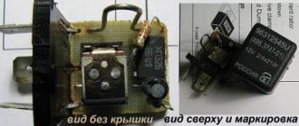
In today's review, I will share with you my impressions of a 5-pin automotive relay purchased on eBay, and also show one of the possible options for its use.
The relay was ordered almost simultaneously with the DRL kit that I talked about a few days ago. For what? Because when using a standard connection, when turning on the side lights or low/high beams, the DRLs still continued to light up. I didn’t find anything good in this, and therefore I began to think about automating their shutdown when turning on the headlights or low beam. The simplest and most logical option seemed to me to be using a relay.
By the way, this is one of the few purchases that I went to the local auto parts store before making. Imagine my surprise when I saw the price in the VAZ store: relay - 5 rubles (about $2.5), a block for it - 2.5 rubles ($1). Total, $3.5 per set offline with us without waiting, versus $1.66 with them. The choice is obvious
DIY turn relay
Sometimes situations arise when the standard turn signal relay fails and it is not possible to purchase a new device. In such a situation, you can try to make a turn signal relay with your own hands to provide the car with the necessary signals. The simplest electronic devices that you can create yourself are simple and easy to use, operate smoothly and reliably. High accuracy is achieved through the use of PWM controllers used in all circuits.
The simplest replacement for an electromagnetic relay is designed for a maximum load power of 150 W. It is connected to the positive terminal. If the IRFZ44 field switch is replaced with the IRF3205 model, then 200 W can be connected. This simple circuit ensures high accuracy of operation. The blinking frequency does not depend on the power of the light bulbs, so LED, halogen and other lamps can be included in the circuit.
The frequency of flashing is directly related to the capacitance of the capacitor. As the capacity increases, the light bulb will blink more rarely, and, conversely, decreasing the capacity will lead to faster blinking. The low-power 1n4148 diode can be replaced by any similar element. When the circuit reaches a power of 80 W, a slight generation of heat is observed in the field-effect transistor area. This means it is ready to use.
There is another simple circuit of a turn relay with a coil - simple, reliable and inexpensive. It is capable of lighting both regular light bulbs and LED ones and is designed for 12 V. The contacts are connected according to the principle of a regular switch, that is, in series with the light bulb. The LED is installed in the circuit as an indicator during commissioning work. The device parameters are adjusted by changing the resistance of the resistor.
It is often difficult for novice auto electricians and people modifying their car to understand the phrase “connect via a relay.” What does connecting via a relay mean and how to do it? Let's figure it out.
Before studying the wiring diagram for any automotive device via a relay, you need to know what a relay is in general and how it works. This is written about in detail here
. Once you understand the operating principle of this simple device, it will be much easier to figure out how to connect it.
The general meaning of connecting via a relay is the load on the switch that controls the installed equipment. All powerful consumers of electricity in the car (for example, headlights, starter, fuel pump, heated rear window, electric power steering) are connected through a relay. Thanks to this, these devices can be controlled by small, beautiful buttons instead of rough and large switches. In addition, in some cases, the relay allows you to save on wires.
The relay is connected to an open circuit in the electrical circuit. Let's look at installing a relay using the example of a gas pump. Power is supplied to it by the engine control unit (hereinafter referred to as the computer) and in order for the computer board tracks to withstand the current consumed by the pump, they would have to be made too powerful. Passing strong current near sensitive electronic components of a computer can affect their operation. To avoid such problems, a relay is installed between the computer and the fuel pump and the computer is connected not to the pump, but to this little “helper”.
The relay, as it were, divides the wire going from the fuse block to the pump into two parts, which can close inside the relay when voltage is applied to the control contacts of the magnet. As already mentioned in the article about the relay device, the control current is very small and cannot damage the computer in any way. The computer supplies voltage to the control contacts of the relay, and it then “connects” the power circuit within itself and connects the fuel pump.
Connecting PTF via relay and button
There are several options for pairing the PTF with the vehicle’s on-board network. Connecting fog lights via a relay using a separate button is the most convenient, safe and correct solution. To complete the job you will need:
- fog lights;
- connection terminals;
- 15 amp fuse;
- four-pin relay;
- connection block;
- wires;
- insulation or heat shrink tubing.
The materials are included in the installation kit and are sold in one set with PTF.
The tools you need are screwdrivers, pliers and a knife for stripping wire insulation.
The wiring must be carried out according to the plan for parallel or series connection of lamps.
The connection diagram for fog lights is shown in the figure.
Operations for connecting PTF are performed in the following sequence:
- Disconnect the negative terminal from the battery;
- Securely fix the relay in the car interior. The space under the instrument panel is suitable for this.
- Secure the button for turning on the fog lights on the “dashboard” (usually there is a separate place for it, covered with a plug).
- Lay the wire from the battery to the relay, secure the terminal on it and connect it to contact “30”.
Important: a fuse must be inserted into the electrical circuit between the battery and the relay, which is best located in the engine compartment close to the battery. This will prevent the wiring from catching fire if there is a short circuit to the housing.
- Connect the button and the 85th relay pin.
- Connect the positive cable to the button input, extending it from the contact lock on the ignition switch. The power supply should be connected to a place where voltage is supplied only after turning the key. This will prevent you from leaving the PTF lights on when parking the car.
- Connect contact “86” to ground using the nearest bolt or self-tapping screw.
- Attach the PTF to the front bumper by removing the plastic plugs. Sometimes there are no special places for attaching PTFs. Then you will have to cut them with a jigsaw or fix the headlights on steel brackets above the bumper.
- Lay the cables from the 87th contact of the relay to the fog lights, connecting them to the sockets.
- Connect the mass output of the PTF to the body.
- Place and secure the negative terminal on the battery.
- Turn the ignition key and make sure the fog lights are working.
During installation, you should insulate the wire connections and terminals using heat-shrinkable tubing or electrical tape.
Connecting contacts
How to connect fog lights via a relay further?
In order for the system to have a twelve-volt network from the dimensions and 85 contacts, it is necessary to run a wire to the relay. Next we extend contact 87 under the pedals to the battery. How to properly connect fog lights via a relay? The circuit includes 30, 85, 86 and 87 contacts. According to the drawing, we connect them. We also install a 15-amp fuse here. Moreover, the closer it is to the battery, the better. Next is contact 86. Everything is simple here - we connect it to the body.
Connection diagram for fog lights via relay
Before starting installation, you need to decide on the connection diagram:
Autonomous, the fog lights will turn on independently, although then the headlights can drain the battery completely, which is fraught with problems. Connection occurs to the positive dimensions or ignition wire +ACC
Watch the video below to see how to properly connect the relay.
With the ignition, in this case, the fog lights cannot be turned on without the engine running, usually the plus from the ignition switch or IGN2 is used, which is best looked for using a voltmeter, since if you use a lamp probe, there is a possibility of damage to the car's electronics.
To connect the fog lights via a relay, it is not necessary to disassemble half of the body. The main part of the work is carried out in the cabin, where it is necessary to provide access to the car's electrical system by removing part of the front panel.
The role of the relay
The relay is necessary to reduce the current in the wires feeding the fog lights to prevent them from melting. It has 4 contacts, two switching and two control, sometimes a five-pin device is used. The excitation winding must have a resistance of at least 70 Ohms; with a lower value, the current may exceed and the fuse may fail. The relay current is 30 A, it is possible to use 70. The contacts are connected according to the following diagram:
- 1st switching - fuse block;
- 2nd switching – fog lights;
- 1st manager - on/off button;
- 2nd manager – mass.
Circuit breakers
After connecting the wires to the relay using terminal blocks, you should install fuses that serve to protect the circuit from short circuits. A 15 A fuse must be installed in the fuse block and power the circuit from the battery through it. If such installation is not possible, the fuse should be installed separately, as close as possible to the battery.
How to connect the power button?
The on/off button must be powered by any 12 V wire. Depending on preference, this can be not only the control wires from the ignition, but also any other source. Most often it is attached to the side lights.
Connecting the headlights themselves is not difficult. The red wire is positive, connects to the relay, and the black wire is ground, to the car body.
After checking that the fog lights are connected correctly through the relay, you can finish installing the fog lights.
On the territory of the Russian Federation, amendments to the rules of the road (TRAF) have been in force for more than 8 years, according to which a moving vehicle during daylight hours must be indicated by low beam headlights, fog lights (FTL) or daytime running lights (DRL). Using headlights and fog lights for these purposes has a number of disadvantages. Therefore, drivers prefer to buy ready-made running light modules and install them in their cars themselves. How to properly connect daytime running lights so that their operation is safe and does not contradict current laws?
Installation requirements
Most motorists who have diligently studied the theoretical course at a driving school know that they cannot voluntarily install devices on their cars that are not provided by the manufacturer, but the installation of fog lights is prescribed in the traffic regulations.
Even if the car from the manufacturer is not equipped with fog lights, each car owner can install them by removing them separately or by redoing the bumper. It must be remembered that when reworking, serious changes are made to the design of the machine, and this is already considered a partial re-equipment.
Installation rules:
- it is allowed to install two fog lights;
- the maximum distance between the headlight and the side surface is 0.4 m;
- The minimum distance from the PTF to the road is 25 cm.
Installation of PTF is carried out in accordance with the established standards.
On a note!
The PTF may need adjustment, since the angle of incidence of the light flux on the road surface must comply with the rules.
How to properly connect fog lights
And you won’t need so many of them, especially since almost every modern car in the minimum configuration already has ready-made places for fog lights and often has a power button already installed. As a last resort, you can install a button or use a free one. Technologically, the factory fog lights are connected in parallel with the rear fog light. But if there is a need to turn them on separately, like daytime lights, then you will have to tinker a little. The headlights are connected only through a relay.
The relay reduces the risk of overload on the entire vehicle network and the load on the power button, especially if a high-power lamp is installed on the fog lights. Often, along with fog lights, they sell ready-made kits, which include a relay, a button, and a set of wires with connectors, but the price of the kit is naturally higher.
About wires
Now you need to deal with the fog lights themselves. As we know, there are only two wires coming from each headlight (“plus” and “minus”, respectively). We connect the latter to the body, that is, it will be our mass. Next, we lift it onto the relay so that the wires are not visible, and connect it to the battery.
This completes the connection of the fog lights via the relay. The connection diagram, as we see, is very simple, so even a novice motorist can cope with this task.
What requirements must PTFs meet?
Finally, let’s note what rules modern fog lights must meet:
In order to illuminate the road surface well, this type of optics must have a clear beam boundary at the top. Thus, the light in the headlights is scattered slightly horizontally above the plane. If the car manufacturer has not provided for the location of the PTF fastenings, in no case should you install the headlights higher than them. Try to place them as close to the roadway as possible. below The location of this optics, the better it will “break” the foggy obstacle in front of you. But don’t forget about ground clearance If. The headlight of the car will be located at a distance of 10 centimeters from the asphalt, then during rainy weather it will constantly get wet, and the water that gets inside the reflector will linger there for several weeks. And throughout this period the glass will be cloudy, and the quality of lighting will deteriorate significantly. On cars like VAZ, the “optimal” classic solution to the problem is to install a steel bumper under the PTF. This way you will “kill two birds with one stone.” Firstly, at such a distance from the headlight, the road will never get wet, and secondly, it looks very attractive and does not disfigure the external appearance of the car. But where there is no point in installing a PTF at all is on the roof (this is what SUV owners often do). The benefit of such illumination is zero, but such a technique will be able to blind in full. If this is not factory optics, it is advisable to purchase it with special plugs. You will significantly increase the service life of the headlights and ensure high safety when driving on rough roads.
And the fog lights are plugged all year round at any time of the day. During operation, it is important to avoid clouding or fogging of the optics glass. To prevent this, you should regularly treat their surface with special polishes (at least once every 2-3 months)
In conclusion, you see, connecting foglights to many VAZ and 2110 other domestically produced cars is a fairly easy task, which every car enthusiast can handle. A fog light is your reliable assistant, which allows you to distinguish objects on the roadway in a timely manner and react to the traffic situation with plenty of time to spare.
Mounting options
Before installing the PTF, an electrical wiring diagram is developed - it will eliminate unnecessary wiring and guarantee the functioning of the electrical circuit.
Bumper mounting
There are 3 installation options: in the openings provided by the manufacturer, on a bracket or in a blind bumper where there is no niche for PTF.
To configure, use a homemade template. It is installed at a distance of 5 cm from the PTF. During adjustment, the coincidence line is set at a distance of 10 cm below the center of the lamps. By adjusting the headlights, they provide increased visibility and minimize the likelihood of being dazzled by oncoming cars.
Installation in a blind bumper
This option is labor-intensive; you have to cut out holes for the PTF.
Procedure:
- Remove the bumper and mark where the headlights will be.
- Drill holes around the perimeter, and then cut out a piece of the bumper with a sharp knife.
- Attach the headlights with appropriately sized bolts. Mount the protective cover - attach it to the bumper.
The headlights are adjusted using a special key - it is included in the package.
Other installation methods
PTF can be placed on a bracket made of durable steel. The bracket is fastened in accordance with the PTF installation standards. The part is secured with self-tapping screws. PTFs are installed at the mounting points and the wiring is connected.
Installation in the opening provided by the manufacturer:
- Raise the car by placing a 20 cm thick wooden beam under the front wheels.
- Remove the protective shields that cover the bottom of the bumper.
- Unscrew the fasteners from the plugs provided by the manufacturer.
- After inserting the PTF into the guides, attach them with self-tapping screws.
If non-original headlights are installed, the dimensions and mounting points may not match. Then the elements have to be adjusted.
DRL from fog lights
Another way to install DRLs according to GOST without changing the appearance of the car is to install LED lamps in the fog lights. I recommend not installing Chinese junk whose specifications indicate a power of more than 5 watts and no cooling system. If the LED power is more than 5 watts, they will overheat and die quickly. For light bulbs without a radiator, in order to explain the too good parameters, the Chinese writes that Cree or Osram diodes are installed. In fact, there are no Cree and Osram there, they are fakes that look like real Cree. Any seller, including the Chinese, will swear and swear by his mother that they are real. I communicate with representatives of Chinese factories and conduct examinations of counterfeit KRI LEDs for domestic companies.
If you don’t have standard halogen fog lights, you can purchase:
- round DRL for PTF seats;
- LED PTF with daytime running lights function;
- just LED PTF.
Don’t forget that according to GOST, fog lights also have a cut-off line. When choosing LED lamps for PTF, try to maintain the cut-off line. So that you don’t hit people you meet in the eyes with your LED spotlight.
Preparatory stage (selection of PTF for Lada Granta)
The range of PTFs is not large; it is represented by several domestically produced models. Some owners claim that PTFs from Opel and Ford are compatible, but the information has not been verified.
| Name / manufacturer / article | Price, rub.) |
| LADA Granta (VAZ 2190) / Kalina 2 / LADA Largus OSRAM Kit 21900-3743010 | from 2800 |
| Kit 21900-3743011 | —/— |
| —/— 2190-3743011 | —/— |
| —/— 2190-3743010 | —/— |
| PTF wiring kit for LADA Granta (2190 2874498) | from 600 |
| PTF "LUCH" set 1118-3743010/11 | from 1800 |
| PTF glass (02B08507) Granta / Kalina 2 / Largus, Datsun | from 750 |
| AUTOMOTIVE LIGHTING / BOSCH (982469641) | from 2000 |
*prices are as of September 22, 2018.
What to have on hand
To carry out the work, we will arm ourselves with the following items:
- keys 8 and 10;
- flat and Phillips screwdrivers;
- a 6-sided key that regulates the spread of light;
- electrical tape, wire cutters, pliers (possibly a soldering iron);
- ties for fastening the wiring and a piece of strong steel wire;
- actually, headlights;
- The most important thing you will need for repairs is a kit for connecting fog lights to Kalina.
Button, relay and wires with connectors Although the plugs included in the package are usually black, you can paint them to match the body color whenever you wish. High-quality fog lights are usually equipped with Philips bulbs that are quite good in their characteristics.
The kit, which includes a button for turning on Kalina's fog lights, as well as wires, connectors and connectors, and a turn-on relay will need to be purchased separately. However, if your car has an air conditioner, then the space for the button is automatically occupied.
Parts for installation in the front bumper
Sequence of work
So, below are detailed instructions, using which you can easily equip your pet with fog lights:
- as in a number of other electrical works, our actions begin by disconnecting the power from the battery (minus terminal);
- Now you can start dismantling the bumper. We need to unscrew the screws and remove the black plastic grilles. It may be necessary to remove the license plate;
We begin work on installing the PTF
- the grilles and bumper are attached with screws and self-tapping screws - you can feel them with your hands, even without a hole. When you remove the bumper, you will see that the mounting points are indicated by arrows. This will allow such work to be completed much faster in the future;
- the wheel arches additionally hold the bumper with 3 self-tapping screws - do not forget to unscrew them as well;
- Now you can carefully begin to remove the sides of the bumper from under the arches, using rocking movements, and remove it entirely. Bend the plugs using a flat-head screwdriver;
- The fog lights themselves are attached to three screws each;
- now we need to extend the wiring into the cabin (as the video in this article shows). Many people recommend removing the driver's wheel and arch protection at this point;
- where the clutch pedal is located, we will find the place where the wires are collected in a bundle and push the seal outward;
- Now you can stretch the wiring using rigid steel wire. The idea is to tighten the wiring from the interior into the space under the hood. You can immediately provide wiring for connecting LED parking lights, alarms, remote hood opening and everything else that has not yet been installed;
PTF assembly
Our new wire blocks will go along with the factory ones, after which they can be tied together with plastic ties like clamps. If there is a need, a wiring diagram for fog lights on Kalina can help with this;
Assembling the headlight completely
We continue our PTF installation algorithm:
- We maintain the required length for the foglights and begin to screw the negative terminals to the bolts. For this purpose, you can use any bolts located on metal parts of the body, except for the engine crankcase mounting bolts, since through them there is no normal contact between the protection and the car body;
- It will be more convenient to run the wire to the right headlight under the radiator grille;
Connecting wires
- if it is necessary to lengthen the wires, twist them, or better yet, solder this place and insulate it;
- the power that the fog lights consume requires connection through a relay, which is controlled by a button (see photo);
- take power from the pink wire that leads to the fuse box (relay K7). It is designed to turn on the high beams, and voltage appears only when the ignition is on;
- use a 15 Amp fuse;
- contacts from the relay are connected via wires with a cross-section of at least 0.75 mm to the wires of the fog lights and to the relay;
- After making all the connections, we need to check how we assembled our kit and whether there is power in the circuit. To do this, connect the ground of the car and check how the headlights shine when turned on by the button;
Bumper with headlight installed
All that remains is to reassemble the bumper in reverse order, making sure that the wires do not get pinched anywhere. The price and degree of complexity of such repairs will be within the power of any Kalina owner. In order to adjust the headlight beam, there is access to the adjustment screw from below.
DIY installation of fog lights
In the process of installing fog lights, several steps will have to be completed:
- installing headlights in the bumper,
- pulling wires,
- connecting the relay and fuse,
- installing a button or replacing the turn control knob and headlights.
Each car model has its own characteristics, so you need to find out in advance the nuances of connecting the PTF on automobile forums or from colleagues with similar cars. You should begin installing fog lights in your car by disconnecting the negative terminal of the battery.
Installing fog lights in the front bumper
Many motorists at this stage are faced with the problem of removing the bumper. An inspection hole or lift will help make the task easier. Here are some simple tips that will make it easier to install PTF in the front bumper:
- First you need to prepare a place where the removed bumper can be placed.
- There is no need to rush and tug the bumper too hard, otherwise the plastic may crack.
- When the bumper is removed, you need to carefully cut holes in the appropriate places for installing fog lights. It is better to do this operation, starting with a small hole, gradually adjusting it to the size of each headlight (this will avoid the formation of cracks through which moisture and dust will subsequently penetrate into the PTF).
- For some fog lights, special decorative plugs are sold, which are selected according to the car model and even the color of the bumper. With such plugs, the process of fitting the holes in the bumper for the fog lights is much simpler.
- Next, all that remains is to screw the fasteners to the bumper, and then use them to secure the headlights themselves.
When both fog lights are installed in place, after mounting the bumper on the car, the power wire connectors are connected to them.
Pulling the wiring to connect the PTF
From the button or knob for turning on the fog lights, you need to stretch the wires to the fuse box. To do this, you will need several wires ranging from 20 cm to 1.5 m in length (depending on the connection diagram and the characteristics of a particular car).
The meaning of the connection is quite simple: the switch should turn on the relay, which in turn will close the power circuit and supply voltage to the fog lights. This work is easiest to do using a universal scheme, suitable for almost any brand of car (see video above).
On cars that are factory-prepared for connecting PTF, everything is much simpler. Otherwise, you will have to install the wiring yourself.
- The positive contacts of each headlight are connected to each other, and then connected with one common wire to the corresponding power circuit relay, according to the PTF connection diagram.
- The negative terminal of each fog lamp is connected to the body or chassis of the vehicle. The connection point must be well cleaned of paint, rust and dirt.
- It is better to secure all additional wires to body elements or other wiring with plastic clamps or electrical tape.
Well, inserting a relay and a fuse into the corresponding socket will not be difficult.
Installation of fog light switch
Depending on the car model, the fog lights can be turned on by a separate button in the car's light on/off control unit or by a knob for turning on the direction indicators and headlights.
In the latter case, it will be necessary to dismantle this unit and install in its place a new unit equipped with a fog lamp switch
When performing this work, it is important to select all the fastening elements of the casings and panels, then dismantling will not bring additional problems with broken plastic parts
After completing all the stages of installing the PTF, all that remains is to check the connection sequence, the reliability of fastening of the connections, connect the negative terminal to the battery and perform a test activation of the foglights. If the fog lights are turned on and off in normal mode, it is necessary to finely adjust the light flux in height (see adjustment diagram). In the future, do not forget to regularly clean the fog lights from dirt and promptly change burnt out bulbs.
Advantages of functional lighting equipment
Fog lights allow you to partially relieve the strain on the driver's eyes during a forced trip in difficult weather conditions. With their help, it is possible to achieve better illumination of the road surface. The greatest importance of headlights lies in the precise supply of light, which determines the illumination of the road.
Precisely adjusted devices illuminate up to 10 meters of space in front of the car, which is quite enough for safe driving in difficult weather conditions. Of course, for this you will need to adhere to a certain speed limit. The headlights are adjusted during the installation of the equipment. The quality of road lighting depends entirely on the setting of the angle of incidence of the light flux.
zom81e › Blog › About installing relays in theory and examples. Part 1
Quite often I have to help with connecting fog lights and other additional equipment. The main problem that novice cadet teachers and others face is connecting the relay. To help in this matter, it was decided to make instructions for this process, or rather a short series of posts devoted to this topic.
Task.
We have at our disposal an OPEL KADETT car, in which fog lights have never been installed before. The existing configuration did not include any wiring for this, and I really want to install a set of universal fog lights. Therefore, we will carry out the installation, as they say, from scratch. They say that they need to be connected via a relay. What does it look like, what does it do and most importantly, how do you connect it? I won't explain all of this. There are plenty of articles on the Internet with this information. Here we will only consider connection options.
Solution.
Option 1.
4-pin with built-in fuse. I believe that this is the most successful option for installing such equipment. The advantages of this design are that the number of handmade twists/solders along the power wire path is reduced, which has a positive effect on the reliability of the wiring and the voltage drop along the way to the consumer. There is also a drawback - if the installation location is poor, where the relay can get into an aggressive environment such as moisture, the contacts may become contaminated. The latter impairs conductivity, which can lead to failure of the relay itself and worsen the performance of the consumer. In the worst case, the wires may be destroyed. But this is unlikely. Such a relay looks like this:
The connection diagram in this case will be like this:
Option 2.
4-pin regular relay. A very rare guest on the shelves today (at least I rarely saw them), but often found in the bins of experienced drivers of the Soviet era. It looks like this: