As you know, a car generator is designed to provide power to all electrical equipment in the car when the engine is running. This unit in domestic “tens” consists of many elements that ensure its optimal operation. One such device is a diode bridge. What functions does it perform, what do you need to know about its malfunctions, and how is the diode bridge of the VAZ 2110 generator replaced? You can find answers to these and other questions below.
Description of the diode bridge on the “Ten”
How is the diode modified and installed in the device? For what reasons can a bridge fail? To begin with, we suggest that you familiarize yourself with the description of the part. If you dismantle the generator assembly from the car and remove the cover, you will be able to see the diode bridge (DM), which is located immediately behind it.
Purpose and functions
What functions does the DM perform:
- The primary task of the device is to convert alternating current into direct current.
- The DM also performs the function of blocking current from entering the stator winding. In this case, the device actually performs the one-way valve option.
- In addition, the DM is designed to increase the safety margin of the generator unit. It allows you to protect the mechanism from the effects of adverse factors and contamination on the device, and this, in turn, can negatively affect the functionality of the mechanism as a whole.
Device
As for the device, in the factory configuration the DM for the “tenth” generator is a monolithic structure. This design, as a rule, is quite strong and reliable, is characterized by its small size, as well as a relatively low price. The only drawback characteristic of factory-made DMs is that if one of the diode elements burns out, local replacement of the damage will not be possible. That is, the car owner will have to completely change the factory axle with his own hands.
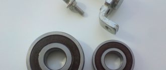
As for the design features itself, the DM consists of:
- two aluminum plates;
- spacers made of plastic;
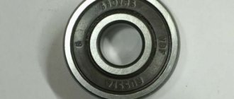
- as well as nine diodes, which are connected to each other by soldering into one structure, that is, a bridge.
Repair and replacement of diode bridge
Since the rectifier device is simple, and the cost of the entire unit is low, the choice of repairing or replacing diodes depends mainly on the availability of free time from the car owner:
- You will have to remove the rectifier assembly in any case;
- Replacing a generator with your own hands will cost a little more, but it will be faster;
- knocking out and pressing in new diodes takes longer, but is cheaper financially;
- if moisture gets on the rectifier assembly regularly, it is easier to remove the diode bridge and take it to a separate unit under the hood, protecting it with a homemade housing, since a working on-board network is worth the time spent.
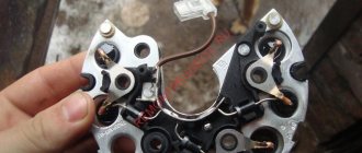
The main mistake when replacing the “horseshoe” of the generator rectifier is shorting the two plates with a bolt. This fastener is swapped from the old diode bridge, and the insulator remains in the square mounting hole. It must be removed and moved to a new location before replacing the diode bridge.
Rice. 12 The insulator under the bolt must be moved to the seat
There are dielectric spacers (getinax or textolite) on the three screws securing the stator windings. The fourth screw without a similar washer is attached to a hole specially designed for it, so it is better to remember its location before removing it.
Rice. 13 One screw is installed without a dielectric washer
When purchasing diodes secondhand on the market or after installing a set of semiconductor devices from your own supplies, their malfunction may be detected:
- in a cold state, the diode “rings” normally (resistance 500 - 700 Ohms in one direction, infinity in the opposite direction);
- After starting the internal combustion engine, when the bridge is heated, the diode “breaks through” and does not cut off the negative voltage value.
Therefore, before checking the diode bridge of the generator with a multimeter, it is better to do it in a state heated to 50 - 80 degrees.
Possible malfunctions: signs and causes
As stated above, the purpose of diode elements is to convert alternating voltage to direct voltage. If one of the diode elements fails, then its malfunction may be indicated by such a sign as a decrease in the voltage level, as well as power in the vehicle electrical network.
For what reasons may problems occur in the operation of the DM:
- Manufacturing defects. As practice shows, many modern DM manufacturers use aluminum shells of fairly low quality in their production. Accordingly, this affects their reliability as a whole. That is why it is recommended to use DM equipped with steel shells, since this directly affects the service life.
- Moisture gets inside the device. Regular exposure to moisture can cause oxidation, in particular, on the surface between the device body and diode elements.
- Engine fluid getting into the unit is one of the most common causes. Exposure to lubricant can lead to disruption of the functionality of the device as a whole, especially if it gets inside the generator unit, directly on the DM.
- Another reason why DMs on “tens” often fail is the polarity of the battery is reversed. If you connect the battery to a charger or accidentally reverse the polarity while “lighting up” the car, this will most likely cause the motor to burn out. Therefore, you should always remember that plus is connected to plus, and minus is connected to minus.
- Regular operation of a vehicle with a weak battery. If the battery does not pull the load and constantly operates under conditions of reduced charge, then the reason may be the inoperability of the DM.
Main signs indicating a faulty diode bridge
A normally operating diode conducts current in only one direction. In the event of a breakdown, a current leak appears, which flows from the on-board network to the starter windings. Today, several types of diode bridges are installed on cars:
- diode bridge without additional cooling;
- diode bridge with passive cooling due to special radiators.
In addition, there are different types of connecting windings and connecting bridge platforms: using welding or soldering. The first sign that the generator is operating unstably due to a broken diode bridge is the rapid and frequent discharge of the battery. There are other reasons why you can indirectly determine the combustion of diodes in a rectifier:
- insufficient spark on the spark plugs;
- headlights with dim light during operation of the power unit;
- interruptions in the sound system;
- significant reduction in cooling fan power;
- poor operation of the air conditioning system.
If any of the above-mentioned signs are noticed, there is no need to panic, but it is better to find out why the diodes burned out, for which you should seek help from the service station specialists.
Diagnostics
The diagnostic procedure must be carried out on a dismantled generator device, so the unit must first be removed. When the mechanism is dismantled, the plastic cover is removed from it, as mentioned above, the DM is located immediately behind it (the author of the video about self-diagnosis with a multimeter is Ramil Abdullin).
For diagnostics you will need a tester - a multimeter - the test is carried out as follows:
- First, the multimeter should be activated in ohmmeter mode. Having done this, the positive probe of the tester must be connected to the diode bus.
- In the same way, connect the negative probe of the tester to the corresponding contact on the diode bridge.
- Next, you need to monitor the tester readings. If the diode bridge is in working condition, then the tester display will show values close to infinity. If there are no such values, then most likely the DM is inoperative and should be replaced. But the diagnosis does not end there.
- Next, you will need to swap the location of the probes, that is, the negative contact is connected to the positive one and vice versa. Having done this, again look at the multimeter reading on the display. If there are no failures in the operation of the DM and the device as a whole is functioning normally, then a value of several hundred Ohms should appear on the tester screen.
- If the DM is equipped with an additional diode, then you can check it too. In this case, the diagnostic procedure is performed in a similar way; you just need to repeat all the steps.
Photo gallery “Self performance test”
Schemes of rectifier blocks for automobile generators.
In rectifier blocks of domestic automobile generators, diodes D104-20, D104-25, D104-35 are usually used, designed, respectively, for maximum permissible currents of 20, 25, 35 A. In three-phase generators, the maximum generator current should not exceed triple the maximum permissible current through diode. So, if diodes are used with a maximum permissible current of 20 A, then when using a rectifier bridge with six such diodes, the maximum generator current cannot exceed 60 A. If a generator with a higher current is required, then you can use a rectifier unit with diodes for a higher maximum permissible current or a rectifier unit with twelve diodes.
Figure 8.1 – Diagram of a rectifier unit with twelve diodes.
It should be noted that doubling the generator current when doubling the number of diodes does not occur, since the current is distributed unevenly between two parallel diodes. From the rectifier unit shown in Figure 8.1 with 20 A diodes, you can get a current of 90-100 A. In order to provide a larger generator output current, you can increase the number of stator winding phases. The number of phases is chosen odd, for example 5,7,9 and so on. When using an even number of phases, the number of rectified voltage ripples decreases by 2 times compared to an odd number of phases, and their amplitude increases, which negatively affects the quality of the generator output voltage.
On special vehicles, a five-phase generator is used with a five-phase main rectifier bridge and a three-phase additional rectifier to power the field winding.
The currents in the field winding are small, so it is not advisable to use a five-phase rectifier. To power the excitation winding, a three-phase rectifier bridge is used, connected so that the voltage at its output is maximum.
Modern generators sometimes use three-phase rectifier bridges with 4 arms.
The fourth arm is connected by input to the neutral of the stator winding and is used to rectify higher harmonics. The fact is that in a real generator the shape of the phase voltage differs from the sinusoid. It represents the sum of harmonics - the first, the frequency of which coincides with the frequency of the phase voltage, and the highest, for three-phase generators, mainly the third.
Figure 8.2 – Diagram of a rectifier block for a generator with five phases and an additional rectifier.
Figure 8.3 – Features of the operation of a rectifier with an additional arm.
A shift of 120° between the phases of the generator for the first harmonic corresponds to a shift of 360° for the third harmonic, 720° for the sixth harmonic, and so on for harmonics that are multiples of three. Therefore, third harmonics and harmonics that are multiples of three different phases of a three-phase generator have vectors directed equally (Uф1mг and Uф2mг in Figure 8.3, a). In linear voltages, which are the vector sum of two phase voltages, harmonics that are multiples of three are destroyed (Ul = Ul').
Figure 8.4 – Phase voltage as the sum of sinusoids of the first and third harmonics.
A conventional rectifier does not rectify third harmonics as it rectifies line voltage.
In order to use the power developed by the third harmonic, an additional arm is added to the rectifier. This arm is connected to the neutral point of the stator winding (see Figure 5.8, b). Thus, phase voltages are supplied to the input of the rectifier unit, which contain harmonics that are multiples of three. Therefore, the rectifier shown in Figure 5.8b additionally rectifies harmonics that are multiples of three. The use of an additional arm increases the generator power by 5–15%.
Expensive cars are equipped with complex electronics that are very sensitive to overvoltages. To get rid of overvoltages, instead of diodes in the rectifier block, zener diodes are used, the stabilization voltage of which is 1.5 times greater than the generator voltage.
Figure 8.5 – Diagram of a rectifier bridge using zener diodes.
If the instantaneous voltage value at the generator output exceeds three times the rated voltage of the generator, the zener diodes will break through and load the generator with additional current, which will lead to a decrease in the pulse amplitude of the generator output voltage.
DIY replacement instructions
In the event of a breakdown, the repair of the DM consists of its replacement, which is done as follows:
- First you need to turn off the ignition, open the hood and turn off the power to the on-board network; to do this, disconnect the battery.
- Once the battery terminal is reset, you will need to disconnect the pink cable responsible for activating the generator assembly. The wire itself is fixed with a bolt and nut; the nut itself will need to be unscrewed.
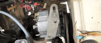
- Now you need to slightly loosen the tension on the top as well as the bottom nuts. Unscrew the tension screws and remove the strap. Inspect it - if the belt shows signs of damage - cracks, delamination - then it is better to change it immediately. If the strap is intact, set it aside.
- After completing these steps, you need to rotate the generator mechanism 90 degrees, this is done so that you can access the lower mounting screw. Unscrew it.
- Next, carefully inspect the body of the dismantled unit. If necessary, clean - there should be no dirt, especially on the connections. Dirt getting inside the generator housing can also lead to its incorrect operation and even failure. Bend the fasteners and remove the cover.
- Next, you need to clean the inside of the rings as carefully, but most effectively as possible.
- After this, all you have to do is dismantle the failed DM and replace it with a working part. When the installation is completed, the structure is assembled in the reverse order. Do not forget to tighten the strap, just make sure that it is not too tight, this is important. Having done this, you will need to start the engine of your car and diagnose the operation of the new DM.
We prepare the diode bridge for self-diagnosis
You can check the functionality of the generator bridge on your own if you understand how the diodes are connected. But before you start diagnosing, you need to carry out preparatory measures. To do this, you need to the generator to gain access to the diodes:
- The fasteners (bolts) holding the front and back covers are unscrewed.
- The next step is to disconnect the housing from the starter winding.
- If the bridge structure is collapsible, then the assembly is unscrewed.
- The positive terminal is disconnected from the generator.
- The method of attaching the minus is checked. If the terminal is independent, it is disconnected.
- After removing the front wall, the bridge is disconnected from the windings. For this purpose, a soldering iron is used to heat the leads until the solder boils, after which they are carefully moved to the side using a screwdriver.
After completing the preparatory work, you need to figure out the question of how to properly check that the diode bridge has burned out ?
Video “How to avoid mistakes when replacing the DM in a VAZ 2110”
More clear instructions for replacing the diode bridge in the “Ten” with a description of the main points and nuances are given in the video below (the author of the video is Semyon Pedan).
Let's start with the fact that a diode bridge is an electrical circuit, a chain of diodes designed to convert alternating current into direct current. A faulty diode bridge is one of the main causes of generator malfunction, and is also a powerful consumer that can drain the battery to zero overnight.
A faulty diode bridge can both discharge and recharge the battery, which can result in major electrical problems. The principle of diodes, in addition to converting current from alternating to direct, is the unipolarity of current transmission from the generator to the battery. In other words, a working diode transmits current only in one direction (generator - battery), a faulty diode transmits current in both directions (battery - generator) or does not transmit anything at all. Diodes burn out due to poor contacts or moisture.
Before you start blaming the diode bridge for all your problems, be sure to check the generator brushes and voltage regulator.
To start checking the diode bridge, you need to remove it, fortunately the process is simple. You can also do without removing the rectifier block (diode bridge), but this is very, very inconvenient.
One way to check the diode bridge is to check the on-board system for current leakage (How to check for current leakage?)! If the current consumption in a stopped engine with electrical appliances turned off is 1A per hour or higher, then most likely the problem lies in the diode bridge. The bridge can only be checked more thoroughly when removed.
Rectifier faults
Since the generator rectifier assembly consists of several semiconductor devices and is protected by a cover in 90% of cases, diagnostics will require electrical tools and partial disassembly of the generator. However, in some cases, the driver can hear signs of a diode bridge malfunction:
- when pulsations occur (alternating voltage is supplied to the on-board network instead of direct voltage), the electric motors of some consumers can reproduce sounds by analogy with a speaker;
- Most often, the drive of the power windows and stove “squeaks”, and the tone changes when the speed of these devices changes, and not the crankshaft speed.
In all other cases, malfunctions of the vehicle generator in the rectifier assembly are diagnosed exclusively by instruments. To do this, you will need a diagram for connecting the diode bridge in a specific modification of the generator, since the symptoms of a mechanical failure are completely similar to the breakdown of electrical parts.
Diagnostics of breakdowns
The rectifier assembly is assembled using various technologies - some parts are attached mechanically, small diodes are soldered into the circuit, large ones are usually pressed in. Therefore, repair of the rectifier may be required, not only if the semiconductor elements fail, but also if they are installed incorrectly on the “horseshoe” of the heat sink plate.
Before ringing a circuit or individual semiconductor, you should visually inspect the structure. Even in the absence of a tester, ohmmeter, or voltmeter, you can use a light bulb and a special battery connection diagram to understand whether the diode is faulty or working correctly.
The diagnostic technique is as follows:
- the back cover is removed from the generator to provide access to the diodes;
- the plate is supplied with a “–” wire from the battery, it is pressed against the housing on the generator, one wire of the lamp touches the diode at the point where the stator winding is connected, the second – to the “+” of the battery, if there is a breakdown, the light will light up;
- The tester is set to 1 kOhm ohmmeter mode; if you swap the multimeter probes, the readings should change from 0 to 400 - 800 Ohms in different directions.
How to remove the generator diode bridge (rectifier unit)?
- We remove the negative terminal of the battery and disconnect/unscrew the wires going to the plastic casing of the generator.
- Disconnect the wire block “D”.
- Remove the protective rubber cap from the tips of the “+” terminal wires. We unscrew the nut securing these wires and remove them from the generator block.
- Next, remove the black plastic casing of the generator itself. To do this, you need to disconnect the three spring clips located around the perimeter of the block.
- We find the voltage regulator, and use a Phillips screwdriver to unscrew its fastenings.
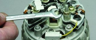
- We take out the voltage regulator assembly with brushes.
- Take the key to “8” and unscrew the 3 bolts securing the bridge.
- We bend the leads to the stator winding to the side and use a Phillips screwdriver to unscrew the capacitor mount.
Let's figure out why the diode bridge in a car generator burns
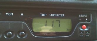
Recently the charger in the car disappeared.
The main component in the electronic system of any vehicle is the generator. Without this unit, a serviceable car, even with a new, one hundred percent charged battery, will not drive for a long time. As follows, this unit must be in working condition at all times, in other words, it must be in good working order.
With all this, initial diagnostics of the car can be carried out without leaving the driver’s seat. But repairs or a detailed check require dismantling the constant current source with its subsequent disassembly in order to open access to the diodes. But before this, the motorist must know the main methods for checking the diode bridge.
How to install a diode bridge (rectifier unit)?
The diode bridge is installed in strictly reverse order.
Background:
My 140 amp generator started howling in an inhuman voice a long time ago, I removed it and sent it for diagnostics. The diode bridge was ordered to be replaced. As a result, the generator was put aside in the nightstand. My old 80-amp generator recently broke down, and I even took the battery with me... In general, I decided to repair the diode bridge on my own, since a new one costs more than 10 thousand rubles, and the auto electrician didn’t know where to buy 50-amp diodes.
You can’t find diodes in Automotive stores; they are rated at a maximum of 30-35 amps, but my task was to find diodes rated at 50 amps. As a result, after surfing the CARGO online catalog, I found the ones I needed. I'm publishing the numbers.
Diode Cargo 50A - 138634 - 6 pcs. Diode Cargo 50A - 138635 - 6 pcs.
For a 140 ampere generator you need 12 diodes - 6+6, for an 80 ampere generator only 6 - 3+3.
We also need a tool, a soldering iron of at least 50 watts with all the accessories. Dye. I chose heat-resistant silicone. I applied it with a brush, so the layer is thicker. Well, not very smelly hands))
Main stages:
— We dismantle the diode bridge — We remove the old diodes — We halve the diode bridge — We install the diodes (carefully hammer them into the case through a wooden spacer) — We assemble the bridge, solder the contacts — We paint carefully in several layers — We put the bridge in place
On one half of the bridge there are diodes of one type, on the other half - of a different type (different polarity). Having the most ordinary multimeter it will not be difficult to understand where each one is located.
Selection of diodes for the rectifier bridge
The main thing they look at when choosing a diode is power.
It depends on the highest rated current generated by the generator. The higher the generator power, the more powerful the diodes. Diodes for the rectifier bridge are conventionally divided into categories: low power diodes, current 300 mA;
medium power diodes, current 300mA – 10 A;
high power diodes above 10 A.
Diodes are divided according to the type of material used, these are germanium and silicon. Most manufacturers prefer silicon diodes. The main reasons for choosing silicon diodes:
· low reverse current;
· high permissible reverse voltage up to 1500 V;
·operability of silicon diodes from -60 to +150оС
Germanium diodes have a low reverse voltage value of up to 400V. They operate in the temperature range from -60 to +85°C.
For example, to replace diodes for a Bosch generator with a 140A for a Touring Custom car. For such a generator you need 50A diodes, for example, Cargo 50A 138634 and Cargo 138635, for a 140A generator you will need 12 pieces, for an 80A generator 6 pieces.
Generator design: its composition
ATTENTION! A completely simple way to reduce fuel consumption has been found! Don't believe me? An auto mechanic with 15 years of experience also didn’t believe it until he tried it. And now he saves 35,000 rubles a year on gasoline! Read more"
The mere fact that a gene is always under high load a priori includes it in the risk group. He needs an eye and an eye. Experienced and caring motorists know this. Beginners and amateurs don’t pay attention, “ruin” the new device and battery, and then wonder why the car doesn’t drive.
What does a gene consist of? Its components necessarily include a rotor or inductor. Its main function is to create a magnetic field inside the device. The rotor has a shaft on which there is an excitation winding. Due to it, the gene is recharged or self-excited.
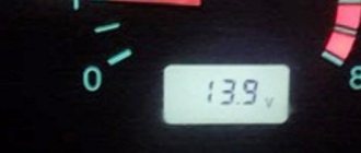
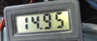
Battery voltage problems in winter
How to increase the charging of the generator on a VAZ 2114 in the winter? This is another problem that concerns the cold season. The fact is that in winter the battery may not have time to warm up. As a result, it constantly discharges.
To prevent such a situation, you should warm it up to at least 0 degrees Celsius. In order to warm up the battery to the desired temperature, you should wait at least 20 minutes. At this time, you need to drive, and don’t stand in traffic jams, otherwise it won’t be of any use.
Why does the gene burn out?
There are many reasons leading to gene (diode) burnout. However, it is customary to highlight the most common:
- dirt or oil has penetrated into the bridge, causing a short circuit;
- on Japanese cars - due to a voltage drop when the generator wears out;
- due to the fault of the voltage regulator, which supplies the rotor, and that, accordingly, to the diode bridge;
- due to a “bad” battery (there are batteries that consume 40A and easily kill the gene);
- the gene was flooded with water;
- the standard fuse responsible for protecting the gene during short circuits has failed;
- The battery terminals were installed incorrectly.
Thus, the generator on the car burns out for various reasons. We are always talking about the combustion of the regulator and diode bridge. Everything is checked quickly based on superficial symptoms. If you need to be 100 percent sure, you have to disassemble the generator.
Forget about fines from cameras! An absolutely legal new product - Traffic Police Camera Jammer, hides your license plates from the cameras that are installed in all cities. More details at the link.
- Absolutely legal (Article 12.2);
- Hides from photo and video recording;
- Suitable for all cars;
- Works through the cigarette lighter connector;
- Does not cause interference to radios and cell phones.