Almost all classic models are traditionally equipped with a standard contact-type ignition system (KSZ). An exception is 21065, which uses a non-contact transistor circuit in which an interruption of the primary winding power circuit is realized using a breaker mounted in the distributor. Below we will consider in more detail how the contact ignition system of the VAZ-2106 is designed and works.
Contact ignition system device
The design of the ignition contact circuit includes the following components:
- lock (switch);
- coil (short circuit);
- breaker (MP);
- distributor (MR);
- regulators, centrifugal and vacuum (CR and VR);
- candles (SZ);
- high-voltage wires (VP).
An ignition coil (IC) with two windings makes it possible to obtain a high current by converting a low voltage.
The mechanical breaker (MP) is structurally made together with a mechanical distributor (MD) in one housing - a distributor. It ensures the opening of the primary winding of the short circuit.
A mechanical distributor (MD) in the form of a rotor with a contact cover distributes current to the spark plugs.
The centrifugal regulator (CR) allows you to change the advance angle (AF) in proportion to the crankshaft speed. Structurally, the CR is made in the form of two weights. During rotation, they act on the movable plate on which the MP cams are located.
The vacuum regulator (VR) makes adjustments to the advance angle (TAA) depending on the load. When the position of the throttle valve (V) changes, the pressure in the cavity behind the V changes. The VR reacts to the degree of vacuum and adjusts the value of the SOP.
Ignition Tuning Guide
Adjusting the VAZ ignition is a priority for many of our compatriots. Before setting the VAZ ignition, you need to check the functionality of the spark plugs and wires. Otherwise, if these elements are not working, you will waste time on adjustments, but you will not achieve the desired result.
So, how to do it right:
- First, unscrew the spark plug and close its hole with your finger or rubber plug. Using a special wrench, rotate the crankshaft until the plug flies out of the hole. If you insert your finger, you will feel the air flow pushing it out.
- The crankshaft must be turned until the mark on its pulley is positioned opposite the mark on the timing cover. After this, you can dismantle the distributor cover. At the same time, make sure that the contact of the timing gear rotor is directed towards cylinder 1.
- Unscrew the nut that secures the distributor and turn it upward. The rotor axis should be set parallel to the axis of the power unit. After this, the nut must be tightened.
- Now, using a control light, connect one of its wires to the coil, namely to its low-voltage contact, and connect the second wire to ground, that is, the car body.
- Turn the key in the lock. The distributor must be turned clockwise until the light goes out. If the lamp is not lit at all, then the system does not need adjustment.
- When the lamp goes out, the breaker should be rotated in the opposite direction. When the lamp lights up again, the device must be fixed in place by tightening the nut.
1. Turn the crankshaft with a wrench.
2. Align the marks on the pulley.
Operating principle and contact system diagram
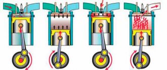
The VAZ-2106 contact ignition system operates according to the following scheme. When the contacts in the breaker close, a low current flows into the primary winding of the short circuit. When the contacts open, a high current is indicated in the secondary winding of the short circuit, which is first transmitted through high-voltage wires to the MR cover and then distributed to the spark plugs.
An increase in crankshaft revolutions leads to an increase in the speed of rotation of the CR, the weights of which diverge to the sides under the influence of centrifugal forces. As a result, the movable plate moves, increasing the SOP. Accordingly, as the speed decreases, the advance angle decreases.
The contact transistor ignition system is a modernized version of the classic circuit, which uses a transistor switch (TC) connected to the circuit of the primary winding of the short circuit. This design solution allows you to significantly increase the service life of the distributor contacts by reducing the current strength of the primary winding.
Ignition system of VAZ2101-VAZ2103 cars, ignition distributorDevice
The ignition system includes: an ignition coil, an ignition distributor, low and high voltage wires and spark plugs.
The ignition order in the cylinders is 1-3-4-2. The installation primary ignition timing is 5-7° (3-5° for BA3-2103 vehicles produced since November 1973).
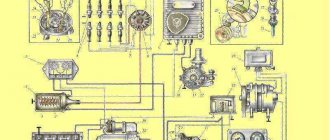
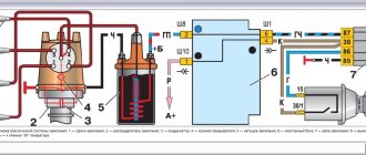
The ignition system circuit consists of two circuits (Fig. 299): 1
the low voltage or primary circuit, which includes the electrical source, ignition switch, capacitor, ignition coil primary, and distributor breaker;
high voltage circuit or secondary circuit, which includes the secondary winding of the ignition coil, rotor with built-in suppression resistor, distributor cap with central contact carbon, high voltage wires and spark plugs.
Distributor. Until 1973, the P125 ignition distributor was used on VAZ-2101 and VAZ-2102 cars. In 1973, a unified ignition distributor P125 began to be used, intended for installation on VAZ-2101, VAZ-2102 and VAZ-2103 cars. It differed from the previously installed one in the characteristics of the ignition timing regulator and the dimensions of the roller shank (Fig. 300.6). Since 1974, the BA3-2103 car has been equipped with the P125-B ignition distributor, and all other cars have the same, non-unified P125 ignition distributor. The P125-B ignition distributor has the same characteristics of the ignition timing regulator as the unified P125, but the dimensions of the roller shank are different (Fig. 300, c).
Rice. 299. Electrical diagram of the ignition system: 1 - battery; 2 - generator; 3 — ignition switch; 4 — ignition coil; 5 — spark plugs; 6 - breaker; 7 - distributor; 8 - capacitor Designation of wire color. Core - brown; Ch - black; GC - blue with a black stripe
Rice. 300. Shafts of the ignition distributor rollers - P125; b - unified P125 c - P12c "
The ignition distribution includes the following devices:
low voltage circuit breaker, octane corrector, centrifugal ignition timing regulator, capacitor, high voltage current distributor.
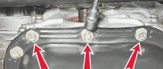
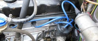
The ignition distributor is installed in the upper left front part of the engine, secured with a special plate 6 (Fig. 301), which presses the housing flange to the upper plane of the cylinder block, and is driven into rotation by the oil pump drive gear, which has a splined hole into which the distributor shaft shank is inserted. .
A cermet bushing 19 is pressed into housing 4 (Fig. 302), in which roller 1 rotates. The bushing is lubricated through a felt wick (filt) from oiler 29. The housing is closed on top with a plastic cover 16, under which the main parts of the ignition distributor are located.
The breaker serves to interrupt the current in the low voltage circuit and consists of a cam 8 with four protrusions and a stand 22 with contacts 27, which the cam opens when rotating. The cam is lubricated with felt felt 20 soaked in oil. An axis is riveted to the stand, on which a lever 24 with a contact is mounted on a textolite sleeve, pressed by a leaf spring 23 to the contact of the stand. A textolite block is attached to the lever, which is in contact with the cam protrusions.
The stand 22 is secured with two screws 21 and 25 on the movable plate 7 of the breaker. The lower end of the lever axis fits into the hole of the movable plate, so when adjusting the gap between the contacts, the stand can be rotated around the axis by first loosening the fastening screws.
The octane corrector allows you to manually adjust the ignition timing within small limits. This may be required after refueling the car, since gasoline of the same brand, but manufactured at different factories, may differ slightly in their
characteristics. The octane corrector rod 5 is attached at one end to the axis 6, riveted to the movable plate, and at the other end to the eccentric axis 18. There are divisions on the eccentric. Each division corresponds to a change in the ignition timing by G along the crankshaft. When the eccentric rotates, the rod 5 moves, turning the movable plate with the stand 22 relative to the distributor shaft.
If you rotate the eccentric in the direction of the arrow <+>, the ignition timing will increase, and in the direction of the arrow <-> it will decrease. In the position of the normal initial ignition timing (5-7° or 3-5° for BA3-2103 vehicles produced since November 1973), the adjustment mark must coincide with the zero of the eccentric scale.
The centrifugal ignition timing regulator automatically changes the ignition timing depending on the engine speed. This is ensured by the fact that the cam bushing 2 (Fig. 303) is connected to the roller 1 not rigidly, but through weights 6 and springs 4 and can be rotated by the weights by 15-15.5° relative to the roller.
When the engine is running, the weights diverge under the action of centrifugal forces, rest their protrusions on plate 5 and, overcoming the resistance of the springs, rotate plate 3 (and therefore cam 2) clockwise relative to the distributor shaft, increasing the ignition timing.
Rice. 301. General view of the ignition distributor installed on the engine: 1 - cover; 2 — octane corrector; 3 - hole for lubrication; 4 - capacitor; 5 — plate fastening nut; 6 — distributor mounting plate
Rice. 302. Ignition distributor P125: 1 - roller; 2 - oil deflector coupling; 3 — hairpin; 4 — body; 5 - traction; 6 - axis; 7 — movable breaker plate; 8 — breaker cam; 9 — driven plate; 10 - drive plate; N - rotor; 12 - central carbon electrode; 13 — output of the central electrode; 14 - resistor; 15 - side electrode; 16 - cover; 17 — weight; 18 — eccentric octane corrector; 19 — roller bushing; 20 - felt; 21 and 25 — screws for fastening the rack with the breaker contacts; 22 _ stand with breaker contacts; 23 — lever spring; 24 — lever; 26 — groove for adjusting the position of the stand; 27 — breaker contacts; 28 — nut securing the tip of the low voltage wire; 29 — roller oiler
Rice. 303. Operation of the ignition timing regulator: a - at idle speed of the engine; b - at maximum roller rotation speed
Rice. 304. Ignition coil B117-A: 1 - external magnetic circuit; 2 and 5 - gaskets; 3 - secondary winding: 4 - primary winding; 6 - output of the end of the primary winding; 7 - cover; 8 - high voltage output; 9 - contact screw; 10 — output <+B>; 11 — body; 12- spring; 13 — coil mounting bracket; 14 - core; 15 - insulator
The higher the rotation speed of the roller, the more the weights diverge to the sides, turning cam 2 to a larger angle.
The springs tightening the plates 5 and 3 differ in the number of turns, wire diameter and length. The spring, which has greater elasticity, is installed with low tension and prevents the weights from moving apart at low engine speeds. The regulator comes into operation at an engine crankshaft speed of 1000 rpm, when the centrifugal force of the weights begins to overcome the resistance of this spring. At higher crankshaft speeds, a second spring comes into action, more rigid, mounted freely on the axles. This provides the necessary change in the ignition timing at different engine speeds.
The distributor consists of a rotor 11 (see Fig. 302) and electrodes installed in a plastic cover 16. The plastic rotor is secured with two screws to the plate 9 of the ignition timing regulator. The rotor is fixed in a certain position. This is provided by square and round holes in plate 9, into which rotor protrusions of the same cross-section fit. The central and outer contacts are riveted on the rotor, between which in the recess there is a resistor 14 with a resistance of 5000-6000 Ohms, designed to suppress radio interference.
A spring-loaded carbon electrode 12 rests against the central contact of the rotor, transmitting high-voltage pulses from the ignition coil to the rotor. When the rotor rotates, these pulses are transmitted from the outer contact of the rotor to the side electrodes 15 embedded in the cover and, further, to the spark plugs. Capacitor 4 (see Fig. 301) with a capacity of 0.20-0.25 μF, mounted on the housing, is designed to reduce sparking between the contacts of the breaker and to increase e. e.e., induced in the secondary winding of the ignition coil.
The ignition coil is used to convert an intermittent low voltage current (12V) into a high voltage current (11-20 kV) to break down the air gap between the spark plug electrodes. It is installed in the engine compartment and is attached to two bolts welded to the bottom of the left wheel mudguard. On cars, an ignition coil of type B117-A (Fig. 304) of domestic production or B 117 produced by NRB can be installed. The characteristics of these coils are the same, and the differences concern only small structural elements. The coil is a transformer on an iron core 14 and an annular outer magnetic core 1. The core is located in a cardboard frame on which a secondary winding 3 is wound, and on top of it a primary winding 4. The windings, together with the magnetic core and core, are placed in a seamless aluminum housing 11 and filled with transformer oil .
The reel body is closed on top with a plastic cover 7, the collar of which is rolled into the body and sealed with a gasket 5 made of oil- and petrol-resistant rubber. The ends of the winding wires are connected to the terminals embedded in the cover. The beginning of the primary and the end of the secondary windings are soldered to pin 10, marked < + B>, and the end of the primary winding is soldered to pin 6 (without marking). The beginning of the secondary winding is connected to the core plates and then through spring 12 and screw 9 to terminal 8 of the high voltage wire. Screw 9 is screwed into the cover and sealed with a rubber washer.
Read more about repair and maintenance of VAZ cars...
Signs of incorrect ignition on VAZ cars
Setting the ignition timing on a vehicle is necessary if the internal combustion engine is being repaired or the distributor is being dismantled. Also, during operation, it undergoes wear and tear, like any other engine systems, and accordingly the following signs of malfunction may appear:
- The motor does not start or has interruptions in operation. Provided that the combustible mixture is supplied correctly, the malfunction may be an incorrect setting of the advance angle, slipping or stretching of the timing chain.
- Poor acceleration and inelasticity of the engine. This means that the combustible mixture is not ignited at the required piston stroke position, which leads to a deterioration in the efficiency of the internal combustion engine.
- High gas consumption. This effect occurs under conditions of late ignition. Part of the combustible mixture does not have time to burn and flies out into the exhaust manifold. In such cases, you can hear characteristic popping noises in the exhaust while the engine is running.
Hard work of the internal combustion engine. This occurs under conditions of early ignition, when the working mixture ignites when the piston position has not reached top dead center.
In such cases, you can hear a characteristic ringing sound in the engine. Such symptoms can lead to burnt out exhaust valves.
Secondary voltage
Now we need to talk a little about secondary voltage, because it determines how well the air-fuel mixture will ignite. Of course, the breakdown voltage should be high if there is a large gap in the spark plug electrodes. You also need to pay attention to the pressure in the combustion chambers. As a rule, the breakdown voltage fluctuates in the range of 8..12 kV. This is the minimum value at which the air-fuel mixture must ignite.
In order for it to light up for sure, it is necessary to double the voltage. As a result, it turns out that a voltage develops in the secondary circuit in the range of 16..25 kV. The reserve is very large, because during the operation of the car, changes constantly occur. In particular, the spark plug gap may gradually increase as the center electrode begins to burn out. The composition of the air-fuel mixture may also change.
If it turns out to be too lean, then for ignition in the gasoline combustion chambers it is necessary to develop a voltage of at least 20 kV. The photo shows the ignition coils that are used in VAZ cars of the classic series. They can be with three terminals or four. The most reliable are the latter, in which there is one terminal from which the high voltage is removed, as well as three for connection to the low-voltage circuit.
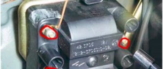
Replacing the ignition switch on a VAZ car
To carry out repair work to replace the ignition switch of a vase, we will need: a screwdriver, a tester and a thin awl. Once you have everything you need, you can begin the repair. On all classic VAZ cars, the ignition switch is located at the bottom, on the left of the steering column. To replace you need:
- Disconnect battery
- Remove the plastic casing by first unscrewing the screws that secure it.
- Then unscrew the two screws securing the ignition switch to the bracket.
- We insert the key and set it to position 0 to disable the anti-theft device.
- Insert the awl into the hole in the bracket and press the latch. Then we take out the lock itself.
- After removal, it is recommended to mark the contact wires so that nothing is mixed up the next time you connect.
Removing the ignition switch on a VAZ-2106 begins with disassembling the steering column casing. We unscrew the five bolts and remove its halves. Before you begin disassembling the electrical part of the lock, it is very useful to disconnect the battery by removing the negative terminal or unscrewing the switch bolt. After this, remove the spring retaining ring from the back of the lock body and remove the contact group. We move it to the side so that it does not interfere, and we begin to remove the lock itself.
It is secured in the steering shaft bracket with two bolts, after unscrewing which nothing happens. It is useless to try to remove the lock from its socket if you do not know about the special stopper. It is located on the lock body under the bracket. We press this stopper into the lock with a thin screwdriver through a small hole in the bracket. Further, according to all the instructions, the lock should be pulled out freely, but this does not work.
An obstacle that is not described anywhere is the anti-theft rod. Even though it is in a “disconnected” state, it still clings to the steering shaft. To remove the lock, you have to manipulate the key. In different positions of the lock cylinder, the anti-theft device also moves and is recessed as much as possible when the key is in the “Starter” position. After a few minutes the lock can be pulled out of the bracket.
Here is the time to write that assembly of the unit should be carried out in the reverse order of removal. And in general, this will be true. First you need to insert the new lock into the bracket, recessing the latch and holding the key in the starter position, tighten the fastening bolts, then connect the wires
Particular attention must be paid to this, because an incorrectly connected contact group can damage the starter or ignition system. We reconnect the wires from the old group to the new one one at a time, checking the numbers on the contacts. After this we assemble the steering column casing
After this, we assemble the steering column casing.
First of all, you need to get rid of the decorative casing of the steering shaft, unscrew the fastening screws and remove it. We performed similar actions when replacing the steering shaft.
After removing the decorative casing, unscrew the two screws securing the ignition switch to the body, then insert the key into the lock and turn on the “0” position, which turns off the anti-theft device. Through the hole in the bracket, press the lock lock with a thin awl and remove the ignition switch from the mounting socket. This completes the repair work to remove the ignition switch.
To replace the contact group of the ignition switch, you need to use a thin screwdriver or an awl to pry the retaining ring from the edge and remove the contact part. When installing a new contact part, orient it so that terminals “15” and “30” are on the side of the locking rod.
At this point, the repair work is completed, install the new ignition switch in the reverse order of removal, connect the wires, transferring the markings from the old switch to the new one. The pinout or connection diagram of the VAZ ignition switch wires is quite simple and understandable, so every car enthusiast can carry out repairs or replace a spare part without the help of car service employees.
Anti-interference
All armored wires, the distributor cap, its body, coil, spark plugs, they have special screens in their design. Separately, it is worth mentioning about high-voltage wires. To eliminate the occurrence of interference, they are manufactured in a special way, in which the resistance is distributed along the entire length.
Inside the ignition distributor, namely on the slider, a constant resistance is included between the central and outer contacts, which can significantly reduce the level of interference. Even the carbon contact, which is located on the spring in the distributor cover, allows us to significantly reduce the level of radio interference.
Repair of contact distributor
It is better to repair the distributor-distributor or diagnose it after first removing the device from the engine. Firstly, it will be much more convenient, and secondly, you will have the opportunity to assess the general condition of the distributor.
Dismantling the VAZ 2101 breaker-distributor
To remove the distributor from the engine, you will need two wrenches: 7 and 13 mm. The order of dismantling work is as follows:
- Disconnect the negative terminal from the battery.
- We find a distributor. It is located on the left side of the power plant cylinder block.
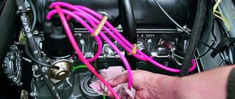
- Using your hand, carefully remove the high-voltage wires from the contacts of the cover.
- Disconnect the rubber tube from the vacuum regulator reservoir.
- Using a 7 mm wrench, unscrew the nut that secures the low-voltage wire terminal.
- Using a 13 mm wrench, loosen the nut holding the breaker-distributor.
- We remove the distributor from its mounting hole along with the sealing ring that acts as an oil seal.
- We wipe the lower part of the shaft with a clean rag, removing traces of oil from it.
Disassembly of the distributor, troubleshooting and replacement of failed components
At this stage we will need the following tools and materials:
- hammer;
- thin punch or awl;
- 7mm wrench;
- slotted screwdriver;
- fine sandpaper;
- multimeter;
- medical syringe for 20 cc (optional);
- anti-rust liquid (WD-40 or equivalent);
- pencil and sheet of paper (to make a list of parts that will need to be replaced).
The procedure for disassembling and repairing the distributor is as follows:
Disconnect the device cover from the body. To do this, you need to bend the two metal latches by hand or using a screwdriver. We inspect the cover outside and inside. There should be no cracks or chips on it.
We pay special attention to the condition of the electrodes. If minor traces of burning are found, remove them with sandpaper.
If the contacts are severely burnt, or the cover has mechanical damage, we add it to the list of replacement parts.
We evaluate the condition of the runner. If it shows signs of wear, we add it to the list as well. Otherwise, clean the slider with sandpaper. Turn on the multimeter and switch it to ohmmeter mode (up to 20 kOhm). We measure the resistance value of the slider resistor. If it goes beyond 4–6 kOhm, we add the resistor to the list of future purchases.
Using a screwdriver, unscrew the two screws securing the slider. Let's take it off.
We inspect the weights of the centrifugal regulator mechanism. We check the condition of the springs by moving the weights in different directions. Under no circumstances should the springs be stretched or dangling. If they are hanging out, we make a corresponding entry in our list.
Using a hammer and a thin drift (you can use an awl), we knock out the pin that secures the shaft coupling. We remove the coupling.
We inspect the splines of the distributor shaft. If signs of wear or mechanical damage are detected, the shaft definitely needs to be replaced, so we “take a pencil” to that too. Using a 7 mm wrench, loosen the nut securing the condenser wire. Disconnect the wire. Unscrew the screw that secures the capacitor. Let's take it off.
We carry out diagnostics of the vacuum regulator UOZ. To do this, disconnect the second end of the hose that comes from the “vacuum manifold” from the carburetor fitting. We again put one of the ends of the hose on the fitting of the vacuum regulator reservoir. We place the other end on the tip of the syringe and, by pulling out its piston, we create a vacuum in the hose and reservoir. If you don’t have a syringe at hand, you can create a vacuum with your mouth, after first clearing the end of the hose of dirt. When creating a vacuum, the movable plate of the distributor must rotate. If this does not happen, most likely the membrane in the reservoir has failed. In this case, we add the tank to our list.
Remove the thrust lock washer from the axle. Disconnect the rod.
Unscrew the tank mounting screws (2 pcs.) with a flat screwdriver.
Disconnect the tank.
Unscrew the nuts (2 pcs.) securing the breaker contacts. To do this, we use a 7 mm wrench and a screwdriver, which we use to hold the screws on the back side. We dismantle the contacts. We inspect them and assess their condition. If they are badly burnt, we add the contacts to the list.
Using a slotted screwdriver, unscrew the screws that secure the plate. Let's take it off.
We remove the movable plate assembly with the bearing from the housing.
We check the bearing for play and jamming by shaking and turning the inner ring. If these defects are identified, we prepare it for replacement. We purchase parts according to our list. We assemble the distributor in the reverse order, replacing the failed elements with new ones. There is no need to install the cover and slider yet, since we will still have to set the gap between the contacts.
Instructions
There are several popular methods for setting the ignition angle on VAZ cars.
Installation with strobe
In this option, you do not need to remove the distributor and valve cover, and the installation time will not exceed five minutes.
- Loosen the distributor nut, noting its initial placement in advance.
- We connect the negative wire of the strobe to the ground of the car, and the “plus” wire to the coil and a special clamp to the wire of the first cylinder.
- The light beam, strictly directed at the pulley, will accurately show the optimal location of the distributor.
By gradually turning the distributor, it is necessary to correctly align the marks on the crankshaft pulley and the marks on the front timing cover. We fix the distributor nut.
Installation by marks
The mark on the pulley number 4 is combined with the mark on the front cover. The values of the marks are as follows: 1-100 degrees, 2-50, 3-00. When installing the ignition. when the engine is running on 92 gasoline, the mark for 0 degrees is selected.
We set the ignition to the light bulb
Before starting the installation, you need to take a 12-volt light bulb and solder two wires to it. Then, using a wrench, turn the crankshaft to the TDC position of the piston of the 1st cylinder.
- We place the marks opposite each other on the crankshaft pulley and the front cover.
- Remove the distributor cover so that the distributor is in the position of the first cylinder.
- We attach one of the wires from the light bulb to the ground of the car, and the second to the low-voltage wire inside the distributor.
- Turn on the ignition. If the ignition is installed correctly, the light will not light up.
- Otherwise, we install the distributor in such a position that the light does not light (i.e., the contacts are open).
When using this installation method, the light bulb can be replaced with a multimeter.
Installation by ear
Warm up the engine to operating temperature. Then loosen the nut securing the distributor. Slowly turn the distributor to the right and left until the engine operates optimally at idle without unnecessary knocking or detonation. Tighten the distributor fastening nut.
Malfunctions of the VAZ 2101 ignition switch and their symptoms
The ignition switch may fail due to the breakdown of one of its component parts. Such malfunctions include:
- breakage of the cylinder (wear of pins, weakening of their springs, wear of pin sockets);
- wear, mechanical damage to the locking rod or its spring;
- oxidation, burning, wear or mechanical damage to contacts, contact terminals.
Breakage of the larva
A sign that it is the cylinder that has broken is the inability to insert the key into the ignition lock or turn it to the desired position. Sometimes the cylinder fails when a key is inserted into it. Then, on the contrary, difficulties arise with its extraction. In such cases, you should not use force in an attempt to restore the lock's functionality. This can break the key, and instead of replacing one part of the device, you will have to change the entire lock.
If the key does not turn or cannot be removed from the lock, the cylinder is most likely broken
Lock rod malfunction
The locking rod itself is difficult to break, but if you apply enough force and jerk the steering wheel while the shaft is locked, it can break. And it is not a fact that the steering shaft will begin to rotate freely. So if the lock breaks while the steering wheel is fixed, under no circumstances should you try to resolve the issue by force. It's better to spend a little time, disassemble it and fix it.
It may also happen that due to wear of the rod or weakening of its spring, the steering shaft will no longer be fixed in position “III”. Such a breakdown is not critical, except that it will become a little easier to steal the car.
The locking rod may also break
Contact group malfunction
Problems with a group of contacts occur quite often. Typically, the cause of its malfunction is burning, oxidation or wear of the contacts themselves, as well as their terminals to which the wires are connected. Signs that the contact group has failed are:
- no signs of operation of instrumentation, lighting lamps, light alarms, heater fan motors and windshield washer when the key is in position “I”;
- lack of starter response when moving the key to position “II”;
- constant supply of voltage to the vehicle’s on-board network regardless of the key position (the ignition does not turn off).
There are two ways to deal with such malfunctions: repairing the contact group, or replacing it. If the contacts are simply oxidized or slightly burnt, they can be cleaned, after which the lock will work normally again. If they are completely burnt out, or worn out so much that they cannot perform their functions, the contact group must be replaced.
If the contacts are burnt or slightly oxidized, they can be cleaned