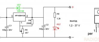
I thought about this thing last winter, when short trips around the city (home-work, home-shop, etc.) with all consumers turned on began to make themselves felt. Many people have probably heard about installing a “boost diode on the voltage regulator,” and so, after reading this article, I thought: in this situation, the voltage in the on-board network is not manually regulated, it simply becomes greater by the value by which the voltage drops when current passes through a diode. First, a little theory: when current passes through a diode, the voltage drops by an average of 0.5 volts (depending on the diode), and the standard regulator thinks that the voltage has dropped in the on-board network and makes the generator produce more voltage. Practice: we take the same circuit as for the “boost diode” and add to it a second diode and a 3-position switch, and you can use any diode, just so that it is designed for a current of at least 5A, then we assemble everything like this scheme
And voila first position 14.2 V, second position 15.4 V, third position 14.8 V
The voltage stabilizer in the on-board electrical system of a car is the most important component without any exaggeration. Not only the stability and longevity of the battery will depend on the quality of its work. At the same time, even a completely serviceable stabilization device does not always guarantee compliance with the voltage and quality of power supply of the vehicle’s electrical network. Car enthusiasts often wonder how to make the generator voltage regulator relay more reliable - contact a service station specialist, assemble or improve it yourself? There are many options.
Modern stabilizers
On modern vehicles, as a rule, self-oscillating relays are installed. They work on the principle of turning off the power to the excitation coil when the voltage reaches the upper limit of 13.5-13.8 V and connecting at the lower voltage threshold of 14.5-14.6 V.
Thus, the output voltage fluctuates constantly. Theoretically, this is not considered a disadvantage, since the voltage does not exceed acceptable limits. Still, this is not entirely safe. Surely experienced drivers know that the weak point of this type of relay is the transition moments when the rotor speed or load current changes sharply. A particularly unfavorable moment occurs with a large load current at low speeds. At these moments, voltage fluctuations often exceed the upper threshold. Due to the short duration of such surges, the battery will not fail immediately, but each time its capacity and, accordingly, resource is reduced.
This problem is solved in different ways. Sometimes car enthusiasts simply replace the self-oscillating relay with an outdated contact-vibration relay. A more optimal solution would be to replace the relay with a pulse-width stabilizer or upgrade the “native” one with the help of small additions.
SHI stabilizer
Pulse-width stabilizers are characterized by more stable operation, that is, an almost constant voltage is supplied to the vehicle network, and small deviations within the normal range are smooth. The device circuit uses the same parts as in the original, but at the same time the K561TL1 microcircuit is included. This made it possible to assemble a multivibrator and a short pulse shaper on the 1st node. The output switch control unit has also been simplified due to the use of a field-effect transistor with increased power.
Stabilizer operation cycle
When the ignition is turned on, a low logic level appears at the output of trigger DD1.1. As a result, transistor VT1 opens with the charging current of the capacitor SZ. It, in turn, begins to supply a high level to the inputs of element DD1.2, simultaneously discharging capacitor C4. When a low level appears at the output, DD1.2 opens the field-effect transistor VT3. The current from the stabilizer output flows through the excitation winding of the generator.
After the pulse stops, a high level is formed at the output of DD1.1 and transistor VT1 closes. Capacitor C4 is charged by the current passing through resistor R5 from the generator, which is controlled by transistor VT2. While the voltage on capacitor C4 drops to the lower switching limit of trigger DD1.2, it will switch. A high level will appear at its output, which will close transistor VT3. In order to protect the input circuits of the DD1 microcircuit, the voltage of capacitor C4 is limited by the diode VD4, which, when it is subsequently charged, will not lead to switching DD1.2. When a low-level pulse is again formed at the output of the generator, the process begins to repeat.
Thus, stabilization is carried out by the duration of the on state of the field-effect transistor, and the process is controlled by a measuring device, as well as a current generator. When the voltage at the generator output increases, the collector current of transistor VT2 increases. As the amperage increases, capacitor C4 begins to charge faster and the duration of the on state of transistor VT3 decreases. As a result, the current that flows through the excitation winding of the generator decreases and, of course, the output voltage of the generator decreases.
When the voltage at the output from the generator decreases, the current at the collector of transistor VT2 decreases. As a result, the charging time of capacitor C4 increases. This leads to a longer period of switching on of the transistor VT3 and the current that flows through the excitation winding of the generator increases. The generator output voltage also increases.
How to check the pH on a VAZ-2110 without removing it
If you find at least one of the listed signs, do not be lazy to check the voltage regulator on your VAZ-2110. This procedure will not take more than 10 minutes. To do this, you will need a voltmeter or multimeter turned on in its mode, as well as an assistant. The verification procedure is as follows:
- We start the car engine and warm it up to operating temperature.
- Without turning off the engine, we connect one voltage probe of the generator, and the second to the “ground” of the device.
- We ask the assistant to turn on the low beam headlights and press the accelerator pedal, keeping the speed at 2000-2500 thousand rpm.
- We measure the voltage with the device.
For the VAZ-2110, the voltage regulator should produce 13.2-14.7 V. This is the norm. If the voltmeter readings differ from those shown, diagnostic measures should be continued.
Voltage Regulator Upgrade
This is another option to improve the quality of the relay and its resistance to transient moments. The standard relay 50.3702-01 was taken as a basis, with only one resistor and capacitor added to the circuit.
In the diagram, the modification is indicated in red and, as you can see, does not require much effort or special experience in radio electronics. When the voltage in the on-board electrical network increases, capacitor C2 begins to charge. In this case, part of the current flows through the base of transistor VT1 and is proportional in magnitude to the rate of voltage increase. This leads to the opening of transistor VT1 and the closing of transistors VT2 and VT3. In this case, the current in the excitation coil decreases, and earlier than without an additional installed circuit. This allows you to significantly reduce voltage fluctuations in the network or eliminate them altogether. The same goes for reducing voltage. In other words, the permissible voltage limits are narrowed, and the smoothness of stabilization increases.
In this diagram, you can also introduce another rational proposal. As you know, the output voltage of the generator is optimized depending on the ambient temperature and in winter it should be higher by 0.8 V, reaching somewhere around 14.6 V. According to the standard, seasonal adjustment is performed by removing or installing jumpers S1, S2 and S3. Installing jumpers eliminates resistors R1, R2 and R3 from the circuit and the output voltage increases. When the jumpers are removed, the transistors turn on again and the voltage drops. To avoid this, the mentioned transistors can be replaced with one trimmer and the output voltage can be adjusted more easily and with greater accuracy.
A generator voltage regulator relay has been created to adjust the “voltage” supplied to the on-board network and to the battery terminals in a given range of 13.8 - 14.5 V (less often up to 14.8 V). In addition, the regulator adjusts the voltage on the self-excitation winding of the generator.
Car alternator output voltage problem
The list of functions of the generator necessarily includes recharging the on-board battery, which is carried out with a certain current to ensure a long service life. The simplest way to set its value is to slightly exceed the voltage taken from the output of the relay-regulator over the current value of the battery voltage. In this case, a serious problem immediately arises, which is due to the fact that, depending on the ambient temperature, the value of this excess should be different.
An obvious and fairly easily implemented solution to obtain a given output voltage using temperature correction of the regulator response threshold by installing an appropriate sensor is of low efficiency. The reason for this is that the temperature in the engine compartment, due to its proximity to a heated engine, differs from the air temperature, and it is not possible to determine the degree of this difference by simple means.
Another problem in determining the set value of the charging current is due to the fact that even at a constant ambient temperature, the load on the on-board network varies within wide limits. This leads to a “failure” in the battery charge level and difficulty starting a cooled engine after parking.
A good way to solve these problems is to switch to a relay-regulator, which makes the necessary adjustments by discretely changing the voltage that the generator creates. The specified value of the response threshold of this device is set by the driver independently using a three-position toggle switch. Some regulators connect automatically and contain an internal sensor that monitors the instantaneous value of the on-board network voltage. In both cases, the selection of the cutoff threshold is carried out taking into account external factors, primarily the current temperature and operating conditions of the vehicle.
Purpose of the voltage regulator relay
Regardless of experience and driving style, the car owner cannot ensure the same engine speed at different times. That is, the crankshaft of the internal combustion engine, which transmits torque to the generator, rotates at different speeds. Accordingly, the generator produces different voltages, which is extremely dangerous for the battery and other consumers of the on-board network.
Therefore, replacing the alternator regulator relay should be done when the battery is undercharged or overcharged, the light is on, the headlights are flashing and other interruptions in the power supply to the on-board network.
Interconnection of car current sources
The vehicle contains at least two sources of electricity:
- battery - required at the moment of starting the internal combustion engine and the primary excitation of the generator winding; it does not create energy, but only consumes and accumulates at the time of recharging
- generator – powers the on-board network at any speed and recharges the battery only at high speeds
Both of these sources must be connected to the on-board network for the correct operation of the engine and other electricity consumers. If the generator breaks down, the battery will last for a maximum of 2 hours, and without the battery, the engine driving the generator rotor will not start.
There are exceptions - for example, due to the residual magnetization of the excitation winding, the standard GAZ-21 generator starts on its own, subject to constant operation of the machine. You can start a car “from a pusher” if it has a DC generator installed; with an AC device, such a trick is impossible.
Voltage regulator tasks
From a school physics course, every car enthusiast should remember the principle of operation of a generator:
- when the frame and the surrounding magnetic field move mutually, an electromotive force arises in it
- The stators serve as the electromagnet of DC generators, the EMF, accordingly, arises in the armature, the current is removed from the collector rings
- In the alternating current generator, the armature is magnetized, electricity appears in the stator windings
In a simplified way, we can imagine that the magnitude of the voltage output from the generator is influenced by the value of the magnetic force and the speed of rotation of the field. The main problem of DC generators - burning and sticking of brushes when removing large currents from the armature - has been solved by switching to alternating current generators. The excitation current supplied to the rotor to excite magnetic induction is an order of magnitude lower, making it much easier to remove electricity from a stationary stator.
However, instead of terminals “–” and “+” constantly located in space, car manufacturers received a constant change in plus and minus. Recharging the battery with alternating current is not possible in principle, so it is first rectified with a diode bridge.
From these nuances the tasks solved by the generator relay flow smoothly:
- adjusting the current in the excitation winding
- maintaining a range of 13.5 - 14.5 V in the on-board network and at the battery terminals
- cutting off the power to the excitation winding from the battery when the engine is turned off
Therefore, the voltage regulator is also called a charging relay, and the panel displays a warning light for the battery charging process. The design of alternating current generators includes a reverse current cut-off function by default.
How to stabilize voltage
We ourselves are to blame, but there are certain complaints about the standard voltage regulator. He, poor thing, cannot take into account the mass of tasks that we pile on his little head in the process of improving the car and adding various devices. A new solution has appeared, especially relevant in VAZ cars of the tenth family and above. Not because these cars are most often stuffed with additional devices, but because the generator and relay regulator are designed close to the rated current consumption.
The three-level voltage regulator VAZ 2110 works in close conjunction with the generator. There is no need to remind that the generator produces an electrical direct current of variable value. That is, the higher the engine speed, the greater the output voltage the generator would produce, and this is not useful for all devices. If there were no voltage regulator, it would jump in the on-board network from 10 to 16 volts and higher, and this is unacceptable for most instruments and devices.
Types of regulator relays
Before you independently repair the voltage regulation device, you must take into account that there are several types of regulators:
- external – increase the maintainability of the generator
- built-in – in the rectifier plate or brush assembly
- regulating by minus - an additional wire appears
- positive regulating – economical connection scheme
- for alternating current generators - there is no function for limiting the voltage on the excitation winding, since it is built into the generator itself
- for DC generators – an additional option for cutting off the battery when the internal combustion engine is not working
- two-level - obsolete, rarely used, adjustment by springs and a small lever
- three-level – supplemented with a special comparison device board and a matching indicator
- multi-level - the circuit has 3 - 5 additional resistors and a tracking system
- transistor - not used in modern cars
- relay – improved feedback
- relay-transistor - universal circuit
- microprocessor - small dimensions, smooth adjustment of the lower/upper threshold of operation
- integral - built into brush holders, therefore they are replaced after the brushes wear out
GU or generator
The generator in any automotive electrical circuit performs the dominant functions. The normal functioning and operation of the machine depends on it. Reliable PG is installed in all foreign cars and models of the domestic automobile industry.
For example, a GU is placed on the “six”, the charge of which satisfies the need for electricity of any standard component. If you do not overload the generating device of the “six”, then the car is capable of driving many, many more kilometers. However, it is important to carry out preventive procedures in a timely manner - monitor the belt tension and the condition of the brushes.
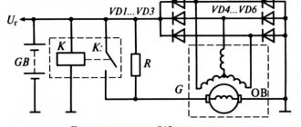
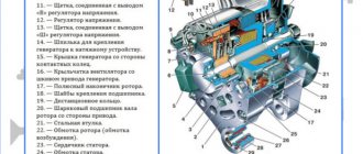
The GU is connected according to the classical scheme. Using the VAZ 2106 generator as an example, let’s consider its functioning. This GU is marked as G-221. It is an AC synchronous electric machine with ELMG excitation. A VB (rectifier) with 6 diodes is built inside the GU.
| 1 | generator rotor winding |
| 2 | generator |
| 3 | generator stator winding |
| 4 | generator rectifier |
| 5 | accumulator battery |
| 6 | ignition switch |
| 7 | battery charge indicator lamp |
| 8 | battery warning light relay |
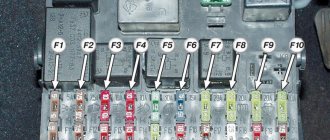
| 9 | fuse box VAZ -2106 |
| 10 | throttle |
| 11 | temperature compensation resistor |
| 12 | additional resistors |
| 13 | voltage regulator |
A simple and understandable scheme that does not require any subtleties or specific knowledge. On the “six” the PG is located on the engine on the right. It is attached to the tension bar with a nut and to the bracket with its claws.
As you can see, the diagram shows an external regulator. It is marked with the number 13. The generator is indicated with the number 2, the fuse box is indicated with the number 9.
Separately, I would like to consider the relay, which plays an important role in the “six” generator circuit. First of all, it serves to provide information to the driver about the charging status. As is known, it is created by a generating device.
The relay is made on the same principle as all devices that function according to the same properties. The connection is made to terminal 30 of the generator. A separate wire goes through the fuses to the 3Z (lock).
The action of the relay boils down to the following: as soon as the voltage of the BS decreases (falls below the 12-volt value), the relay contacts open, the indicator is activated, giving a sign to the driver.
To better understand the connection diagram, it is recommended that you also familiarize yourself with the principles of battery charging:
- as soon as the key is turned into the 3Z, an electric pulse is supplied to the relay regulator through the fuse (pin 15);
- in the regulator the voltage is transformed and goes further to the positive brush of the GU;
- then, through the brush, the voltage goes to the excitation winding of the GU;
- then - to the negative brush, through which it is brought to ground.
After the relay is activated or after the normal voltage value has been reached in the BS, the GU begins to generate current with the required value. The indicator lamp goes out, and the circuit starts working in factory mode. But when the total voltage drops, the current is not enough, and the contacts open, which leads to the discharge lamp burning.
The constant switching on of the charge indicator lamp indicates that the gene is not working properly. This happens for various reasons. First, you should check the fuses: if they are active, then both relays deserve attention: the regulator and the charger. If they are also in order, then faults must be looked for in the generating device itself.
Before proceeding with replacing the relay, it is recommended to carefully check the functioning of the regulator. The car starts, the speed is kept within the range of 2500-3000 rpm. After this, you need to turn off all current consumers, except the ignition. Then you need to measure the voltage at the battery terminals.
Charging may disappear in the following cases:
- If the generator brushes are worn out.
- In case of malfunction of the generating device.
- If the charging relay is faulty.
- If the rectifier unit (diode bridge) fails.
Thus, installing an external relay-regulator instead of a built-in one will bring a lot of benefits. The fact is that modern charging systems have much more power. Thus, modern memory systems are much more complex than old-style systems.
Forget about fines from cameras! An absolutely legal new product - Traffic Police Camera Jammer, hides your license plates from the cameras that are installed in all cities. More details at the link.
- Absolutely legal (Article 12.2);
- Hides from photo and video recording;
- Suitable for all cars;
- Works through the cigarette lighter connector;
- Does not cause interference to radios and cell phones.
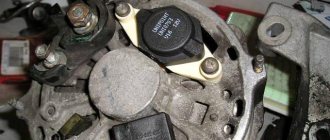
On the “classic” you can find 2 types of voltage regulator relays: built into the generator and external. The difference lies in the model of the generator that is installed on the car.
On older Zhiguli models (VAZ 2101, 2102, 2103, 2106, 2121 with carburetor engines) a G-221 generator is installed, and the external voltage regulator is a small “box”, which is secured with two nuts on the left mudguard of the body. It is precisely the replacement of such a regulator that will be discussed in this article.
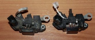
On later VAZ models (2104, 2105 and 2107) there is a G-222 generator, and the voltage regulator is already built into the generator housing and is a small black “tablet”.
Operating principle of the regulator relay
Thanks to built-in resistors and special circuits, the relay is able to compare the amount of voltage generated by the generator. After which, too high a value leads to the relay being turned off, so as not to overcharge the battery and damage electrical appliances connected to the on-board network.
Any malfunctions lead to precisely these consequences: the battery becomes faulty or the operating budget increases sharply.
Summer/winter switch
Regardless of the season and air temperature, the operation of the generator is always stable. As soon as its pulley begins to rotate, electric current is generated by default. However, in winter the insides of the battery freeze, and it replenishes the charge much worse than in summer.
The summer/winter switches are either on the body of the voltage regulator, or the corresponding connectors are marked with this designation, which you need to find and connect the wiring to them depending on the season.
There is nothing unusual in this switch, these are just rough settings of the regulator relay, which allows you to increase the voltage at the battery terminals to 15 V.
Connection to the generator's on-board network
If, when replacing a generator, you connect a new device yourself, you need to take into account the following nuances:
- First you should check the integrity and reliability of the contact of the wire from the car body to the generator housing
- then you can connect terminal B of the regulator relay with the “+” of the generator
- Instead of “twists” that begin to heat up after 1–2 years of operation, it is better to use soldering of wires
- the factory wire must be replaced with a cable with a minimum cross-section of 6 mm2 if, instead of a standard generator, an electrical appliance rated for a current of more than 60 A is installed
- The ammeter in the generator/battery circuit shows which power source is currently higher in the on-board network
Advantages of using a three-level relay and features of its installation
In practice, three-level regulators designed for the 9th and older VAZ models have become widespread. This is due to the fact that replacing the standard relay with a three-level one provides the following advantages:
- stabilization of alarm operation in severe frosts;
- increasing the brightness of headlights and interior lighting lamps;
- a sharp increase in the efficiency of the heater;
- increasing the speed of power windows.
Kits for VAZ “ten” and 14th models are quite common; there are also devices for “Volga” and “Gazelle”. Their use on these vehicles gives a similar effect.
A three-level relay-regulator is purchased in the form of a ready-to-install kit, which includes detailed illustrated instructions. The main elements of the kit are a contact group, a relay itself with a slide-type switch for selecting the stabilization voltage, and connecting wires.
Before starting replacement work, it is advisable to charge the battery and then disconnect its negative terminal.
The contact group of the new device is mounted directly on the seats of the previously dismantled old one; installation does not require the use of adapters and other auxiliary elements. The connecting wire is pulled through the generator cover (you may need to cut a hole in it to the required size), and the relay itself is attached to a free mounting stud with the terminals facing down. When installing, additionally check for reliable ground contact. After installing and assembling the generator, we check it.
Regulator relay diagnostics
Voltage regulator failures can be determined by indirect signs. First of all, this is incorrect battery charging:
- overcharge - the electrolyte boils away, the acid solution gets on the body parts
- undercharging - the internal combustion engine does not start, the lamps are dimly lit
However, it is preferable to diagnose with instruments - a voltmeter or tester. Any deviation from the maximum voltage value of 14.5 V (in some cars the on-board network is designed for 14.8 V) at high speeds or the minimum value of 12.8 V at low speeds becomes the reason for replacing/repairing the regulator relay.
Built-in
Most often, the voltage regulator is integrated into the generator brushes, so a level inspection of this unit is necessary:
- After removing the protective cover and loosening the screws, the brush assembly is removed out
- When the brushes are worn out (less than 5 mm of their length remains), replacement must be carried out without fail.
- Generator diagnostics with a multimeter are carried out complete with a battery or charger
- The “negative” wire from the current source is closed to the corresponding regulator plate
- The “positive” wire from the charger or battery is connected to a similar relay connector
- the tester is set to voltmeter mode 0 - 20 V, the probes are placed on the brushes
- in the range of 12.8 - 14.5 V there should be voltage between the brushes
- when the voltage increases above 14.5 V, the voltmeter needle should be at zero
In this case, instead of a voltmeter, you can use a lamp, which should light in the specified voltage range and go out when this characteristic increases above this value.
The wire that controls the tachometer (marked W only on relays for diesel engines) is tested with a multimeter in tester mode. It should have a resistance of about 10 ohms. If this value decreases, the wire is “broken” and should be replaced with a new one.
Remote
There are no differences in diagnostics for the remote relay, but it does not need to be removed from the generator housing. You can check the generator voltage regulator relay with the engine running, changing the speed from low to medium, then high. Simultaneously with the increase in speed, you need to turn on the high beams (at a minimum), the air conditioner, the monitor and other consumers (at a maximum).
Thus, if necessary, the vehicle owner can replace the standard voltage regulator relay with a more modern modification of a built-in or remote type. Diagnostics of performance is available on your own with a regular car lamp.
Device check
The relay-regulator of the voltage of the VAZ 2106 generator, “kopecks”, and foreign cars is checked equally. As soon as you remove it, look at the brushes - they should be more than 5 millimeters long. If this parameter is different, the device must be replaced. To carry out diagnostics, you will need a constant voltage source. It would be desirable to be able to change the output characteristic. You can use a battery and a couple of AA batteries as a power source. You also need a lamp, it must run on 12 Volts. You can use a voltmeter instead. Connect the plus from the power supply to the voltage regulator connector.
Accordingly, connect the negative contact to the common plate of the device. Connect a light bulb or voltmeter to the brushes. In this state, voltage should be present between the brushes if 12-13 Volts are supplied to the input. But if you supply more than 15 Volts to the input, there should be no voltage between the brushes. This is a sign that the device is working properly. And it doesn’t matter at all whether the voltage regulator relay of the VAZ 2107 generator or another car is diagnosed. If the control lamp lights up at any voltage value or does not light up at all, it means that there is a malfunction of the unit.