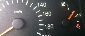
If the arrow on the dashboard of the fuel level sensor of a Lada Priora remains motionless, regardless of the amount of gasoline filled, then it is necessary to urgently begin to look for problems that could cause this type of problem. All work can be done independently in a garage, and the only necessary tools you will need are a set of screwdrivers, pliers and a 10mm wrench.
Fuel level sensor for Lada Priora
If the arrow on the dashboard of the fuel level sensor of a Lada Priora remains motionless, regardless of the amount of gasoline filled, then it is necessary to urgently begin to look for problems that could cause this type of problem. All work can be done independently in a garage, and the only necessary tools you will need are a set of screwdrivers, pliers and a 10mm wrench.
Lada Priora hatchback 2008, engine Gasoline 1.6 liter., 98 hp, Front drive, Manual - DIY
Comments 1
After replacing the sensor with a new one, it was still glitchy for the first 3 days (it hung in the lower position and did not float up), then it got used to it and it became just great.
We pay for photo reports on car repairs. Earnings from 10,000 rubles/month. Write:
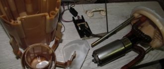
Replacing the fuel level sensor itself on a Lada Priora is not that difficult, although to do this you will first need to remove the fuel pump. However, this is a small obstacle to not changing the sensor yourself. Replacing the fuel level sensor on a Priora is in many ways similar to a similar procedure on Kalina and Grant (1.6 engine), only the sensor mounting is slightly different.
Troubleshooting
The Lada Priora FLS is relatively inexpensive, but before purchasing a new part, you should make sure that the inoperability of this element is not caused by a banal lack of contact between individual elements of the electrical circuit. Most often, such problems can be observed directly at the places where the wires are connected to the sensor. It is recommended to remove the terminals and clean the contact elements using “zero” sandpaper.
If after performing this operation the fuel level indication is not restored and there is no visible damage to the electrical wiring, then you will need to replace the FLS with a known good product.
What's the result?
Taking into account the above, it becomes clear that although the fuel level sensor is structurally simple, various breakdowns (both mechanical and electrical) can disable this element or cause malfunctions in its operation.
One way or another, the problem needs to be solved, otherwise the driver will have to constantly separately record data on how many kilometers have been traveled since the last refueling, how much more can be driven and when to refuel.
Finally, we note that often the best option is to replace the FLS with a new one; at the same time, it may also be necessary to change the fuel level sensor float. Less often it is possible to carry out repairs by removing oxides, moving to working sectors, etc.
At the same time, the most serious nuisance that leads to incorrect fuel level readings is considered to be a damaged gas tank. In order for the fuel sensor to work normally, in this case it is necessary to repair or replace the fuel tank.
Why is it necessary to clean the fuel pump mesh? When is it better to change and how to clean the fuel pump mesh? How to properly remove the fuel pump, subtleties and nuances.
What is the FLS fuel level sensor intended for: the design of the fuel sensor, types of fuel sensors and features, the operating principle of the FLS.
How to change a fuel pump. Location of the fuel pump, releasing pressure in the system, unscrewing the fuel lines, removing the pump, reassembling.
The causes of whistling and increased noise during operation of the fuel pump are overheating of the pump. How to diagnose and fix the problem yourself. Tips and tricks.
Why does the fuel pump grid need to be changed? How to remove the fuel pump yourself to replace the filter. Features of reassembly after replacing the fuel pump mesh.
How to determine why the fuel pump does not pump or works poorly. Fuel rail pressure, pump diagnostics. Wiring, relays, fuel pump fuses.
Replacement process
Before you start replacing the Lada Priora FLS, it is recommended to leave a minimum amount of gasoline in the tank. Then the car is placed on a level surface, and the work is performed in the following sequence:
- Recline the rear seat.
- Open the hatch that blocks access to the sensor.
- Disconnect the wires from the contacts.
- Clean the part of the gas tank where the FLS mount is located from dirt and dust.
- Loosen the clamps and remove the hose.
- Unscrew the 8 bolts with a “10” key.
- Remove the sensor from the gas tank.
Installation of a new sensor is carried out in the reverse order of removal. When performing installation work, care must be taken not to damage the float or bend the lever to which this element is attached. The bolts securing the part should be tightened evenly, taking care not to strip the threads.
After installation and connection, the operation of the FLS should be checked. To do this, fill approximately half the tank with gasoline and drive on a bumpy road at slow speed. If the sensor readings approximately correspond to the fuel level, and the arrow on the dashboard does not deviate when driving on an uneven surface, then replacing the sensor can be considered successful.
Removing and disassembling the fuel module
We are carrying out work to replace the fuel level indicator sensor, fuel pressure regulator, strainer and fuel pump. Relieve the pressure in the power system (see “Replacing the fuel filter”). Disconnect the wire terminal from the negative terminal of the battery. Inside the car, lift the rear seat cushion (see “Removing the rear seat”) and bend the sound insulation valve that closes the hatch cover in the floor of the body under the rear seat.
Use a Phillips screwdriver to unscrew the two screws securing the hatch cover...
...and remove the cover. Lifting the wire harness block clamp...
...disconnect the block from the fuel module cover connector.
By pressing the spring clamp, disconnect the tip 1 of the tee from the fitting of the fuel module cover. By squeezing the clamps (in the direction of the arrows) of tip 2 of the fuel supply tube, disconnect the tip from the fitting of the fuel module cover.
Using a 10mm socket with an extension, unscrew the 8 nuts securing the pressure plate of the fuel module. Remove the spring washers and the ground wire from the tank neck studs.
Remove the pressure plate.
Carefully, trying not to damage the fuel level indicator sensor float, remove the fuel module from the tank. We drain the remaining fuel in the module into a previously prepared container.
If replacement is necessary, remove the ring plastic spacer.
Please note: when installing the spacer later, its cut must coincide with the protrusion on the fuel module cover
Remove the rubber sealing gasket. We close the hole in the fuel tank to prevent foreign objects from getting into it. We disassemble the fuel module on a workbench. If it is necessary to replace the o-rings of the fuel pressure regulator or the regulator itself...
...disconnect the tip of the ground wire from the terminal on the regulator body.
Using a screwdriver, remove the fuel pressure regulator mounting bracket.
Using pliers, remove the regulator from the module cover socket.
Remove the two rubber sealing rings of the regulator. Install the fuel pressure regulator in reverse order. We replace the regulator O-rings with new ones. Before installing the regulator O-rings, apply a thin layer of engine oil to the O-rings. To replace the fuel gauge sensor or fuel pump, the fuel pressure regulator does not need to be removed. From the inside of the module cover...
...use a screwdriver to press out the fixing plate of the common wire block...
...and disconnect the wire block from the cover connector. By pressing the latch...
...disconnect the wire block from the fuel pump. To remove the fuel level sensor...
...we release the two sensor latches...
...and move the sensor along the grooves of the housing towards the cover.
Remove the fuel level indicator sensor with wire blocks. Install the fuel level indicator sensor in the reverse order. When replacing the fuel pump, it is better to remove the fuel level sensor to avoid damaging it.
Use a screwdriver to pry up the drain tube... ...and disconnect it from the module body.
There is a retaining ring located in the groove of one of the guide posts of the module cover. We remove it by prying it with the blade of a slotted screwdriver.
By pressing the four latches of the pump holder...
...remove the fuel module cover assembly with the holder and the fuel pump.
Remove the spring from the guide post of the cover.
...remove the strainer.
Remove the lock washer from the slot in the strainer housing.
Using a screwdriver, press out the plastic latch of the holder...
...and use your finger to push the fuel pump out of the holder. We heat the plastic corrugated tube on the pump nozzle over a container of boiling water...
...and remove the tube from the pump connection. The car is equipped with a BOSCH fuel pump 0580454035.
A valve is installed in the fuel module housing to prevent fuel from leaking out of the housing. Assembling and installing the fuel module is carried out in the reverse order
When installing the strainer, pay attention to the condition of the lock washer; if it is dented, it must be straightened or replaced. When installing the fuel module into the tank...
...arrow 1 on the fuel module cover should be directed backwards (towards the trunk). Arrows 2 on the fittings of the fuel module cover indicate the direction of fuel movement. We put the tips of the tee and the fuel pipe onto the fittings of the module cover until the latches click. Before closing the hatch cover in the floor of the body under the rear seat, it is necessary to check the tightness of the fuel module connections. To do this, connect the wire terminal to the “negative” terminal of the battery and turn on the ignition.
Stopped showing the fuel level of Priora 16 valves
- To the beginning of the forum
- Forum Rules
- Old design
- FAQ
- Search
- Users
stretch out all the masses. if it doesn't help, change the air
But here, it seems, there is a problem with the compatibility of the “smart” device (more precisely, its firmware) and the FLS itself
If you pour 5 liters into an empty tank, the needle may not rise, or just a little bit.
Thanks for the advice. I will talk to IPG. Here's another reason.
Fill up with gas to start...
I think he’ll send you there—to a gas station, I mean.
By the way, I remembered... I had a similar problem over the summer. It turns out there was half a tank, I go to the gas station and fill it with 20 liters. The arrow shows 35l. Well, I think at the gas station they fucked me with 5 liters. freaks
Well, in general, I skated again to the forecastle, I arrive at another gas station, fill it full and again the same crap, the needle does not reach 5 liters to full. Well, I still think the float is leaky. I rolled it down to the remaining 10 liters in the tank. I filled it with ten - it shows exactly half a tank. And until it’s full, well, it doesn’t reach five liters and that’s it. In general, this happened several times and you drive the same way, and the needle still stands at 3/4 of the tank, then it only slowly decreases. In general, after several refuelings the needle began to slowly rise while driving, and then immediately after refueling it began to rise. I began to wonder why this could be and there was only one conclusion. When I went to visit relatives in another city, the car was parked near the house on a hill for a week, so the front was very pulled up and the back was down. And this crap appeared right after that. Fuck knows what was stuck in the FLS, but now it seems to have been cured.
Source
Troubleshooting
The Lada Priora FLS is relatively inexpensive, but before purchasing a new part, you should make sure that the inoperability of this element is not caused by a banal lack of contact between individual elements of the electrical circuit. Most often, such problems can be observed directly at the places where the wires are connected to the sensor. It is recommended to remove the terminals and clean the contact elements using “zero” sandpaper.
If after performing this operation the fuel level indication is not restored and there is no visible damage to the electrical wiring, then you will need to replace the FLS with a known good product.
Replacing the FLS on a Priora with your own hands
So, when the pump is removed from the gas tank, you can begin to remove the sensor. For this we need a flathead screwdriver.
First of all, disconnect one wire by pulling it slightly down.
Then the second, but already a plug with several wires:
The plugs are attached quite simply, but at the same time securely. In order to remove them, you need to press the latches and at the same time pull to the side. After this, you can release the wires from the module and pull them out.
Then you can begin to remove the FLS. To do this, move the two locking hooks to the side, as shown in the photo below.
And move the FLS up until it is completely removed.
The result of the work done can be seen in the photo below, when the fuel level sensor is completely removed from the Priora fuel pump module.
As you can see, there will not be any particular difficulties when replacing this sensor. The price of a new one is no more than 350 rubles, so this repair will not be too expensive. Installation occurs in the reverse order and will not take more time than removal.
For greater clarity, I advise you to watch the video report below.
How does the device work?
To understand the problem yourself, you need to understand how the fuel level is measured and information is transmitted to the device indicator. The circuit implemented in most vehicles includes the following main elements:
- a float made of lightweight polymer is immersed in the gas tank and is often combined with the pump block;
- gasoline sensor – lever-type potentiometer (otherwise known as rheostat);
- pointer arrow with scale;
- connecting wires.
In many modern cars, an electronic control unit is connected to the system.
The classic rheostat is an open coil of high resistance wire. A lever equipped with a contact and attached to the float rises or falls with the level of fuel in the tank, and the contact moves along the turns of the winding. The classic scheme works simply:
- The rheostat and the pointer device are connected in series in the circuit, both are powered from the vehicle's on-board network.
- When moving the float with the lever, the resistance of the potentiometer changes.
- A change in resistance causes an increase or decrease in the current in the circuit, to which the indicator arrow reacts. The scale is graduated according to the resistance values corresponding to the filling of the gas tank.
The updated version of the system works with the participation of a controller. The fuel level arrow receives a processed digital signal from the electronic unit that supplies power to the potentiometer. The principle of operation does not change, but the circuit allows you to obtain more accurate readings.
Connecting the on-board computer of the VAZ tenth family
The route on-board computer (MBK or BC) has become an integral part of modern cars. I don’t think it’s worth talking about how useful it can be, but how to connect the on-board computer yourself is of interest to many. And also, is it possible to connect an additional on-board computer to the car? There are many trip computers for the “ten” (State, Gamma, Multitronics, Orion, Prestige, etc.), and as a rule, instructions for the on-board computer that describe the connection process are included. But it’s not uncommon for us to receive a used bookmaker, without the documentation we need. Installing an on-board computer with your own hands is not difficult, because the necessary block for connecting the BC is already inside the dashboard. It is a 9-pin trapezoidal block. The best way to get to it is through the right window of the dashboard. The pinout of the standard on-board computer connector is shown in the figure. Additional 10 and 11 contacts are not used on all BCs and are intended for connecting an external air temperature sensor. After we insert the block into the trip computer, all that remains is to connect the K-line. Why is K-Line needed? It is through this wiring from the ECU that the most significant information for us is transmitted (error codes, internal combustion engine temperature, etc.). The K-line is located in the diagnostic block (which is used at service stations to diagnose a car) to the left of the steering wheel, not far from the gas pedal. Our task is to connect the K-line to the on-board computer, that is, lay a separate wire from the BC block to this diagnostic block. Thus, the on-board computer will receive the information it needs and the diagnostic block will remain operational. The diagnostic block of the VAZ 2110, depending on the year of manufacture of the car, can be of two types: Euro-2 (GM) or Euro-3 (ODB-II). Where to find the K-line in the block is shown in the diagrams:
Why does the fuel level sensor show incorrectly or the fuel level does not work?
Let's start with the fact that many people mistakenly believe that if the fuel level sensor does not work, this does not affect the overall functionality of the engine and its systems. In fact, in such a case, there is not only a great risk of being left without fuel at the most inopportune moment (for example, far from a gas station on the highway), but also of causing certain vehicle devices to fail.
More precisely, we are talking about the fuel pump. In a nutshell, the fuel pump in the power supply system of injection engines is submersible, constantly in the fuel, and is cooled by the fuel.
It is for this reason that a normally working fuel level sensor indicates that there is no fuel and refueling is needed. When the level is reduced to the limit, the warning lamp lights up. At the same time, at least 3-5 liters of fuel still remain in the tank itself, which allows you to partially cool the pump, avoid debris and dirt from getting into the fuel supply system from the bottom of the tank, and also drive a few more kilometers if necessary.
If the sensor shows incorrectly or does not work, the driver often has to drive with the level light on, there is always too little fuel in the tank, the pump overheats (especially in hot weather) and quickly fails. Also, dirt from the bottom of the tank can prematurely clog the fuel pump filter (mesh filter), as well as the fuel filter itself, etc.
In other words, if the fuel sensor in the car does not work, this can cause not only inconvenience, but also a number of other troubles. In order not to have to clean the fuel system, as well as to increase the service life of the fuel pump or avoid replacing it, it is recommended to troubleshoot the FLS as soon as possible.
Priora dashboard test
order in accordance with pressing the button: 1. Tidy test 2. Software version (1.1 IMHO) 3. Errors (the number 14 was displayed) 4. Deleting errors. Can you tell me more about this procedure? Which panel?
Can you tell me more about this procedure? Which panel?
if these are errors, then not the ECU, but the combination itself
This is what is written in the “Murzilka”: 1. The ignition is turned off. Battery included. 2. Press the “Reset” control button and, holding it pressed, turn on the ignition. All positions of the familiar areas (segments) should light up on the LCD—LCD control. 3. Press any of the control buttons. The LCD should display the program version (Ver 1.0). 4. Press any of the control buttons. The following error codes (if any) should be displayed on the positions of the first and second lines of the LCD: 2-overvoltage of the on-board network; 3-fuel level sensor error (if a break in the sensor circuit is detected within 20s); 4-error of the coolant temperature sensor (if an open circuit of the sensor is detected within 20s); 5-outside temperature sensor error (if there are no sensor readings within 20s, indication on the LCD is “-C”); 6-engine overheating (the criterion for triggering the acoustic alarm has been met); 7-emergency oil pressure (the criterion for triggering the acoustic alarm is met); 8-defect of the brake system (the criterion for triggering the acoustic alarm is met); The 9-battery is discharged (the criterion for triggering the acoustic alarm is met); E-determination of an error in a data packet stored in EEPROM. 5. Press the “Reset” control button and hold it for no more than 3 seconds. (maybe a typo, I need more than 3c). Error codes should clear to zero. 6. Press any of the control buttons. All positions of the familiar areas (segments) should light up on the LCD—LCD control.
From yourself if you do not press any control buttons for about 15-30 seconds. the panel enters the operating state.
“Reset” is the one that resets the daily mileage
PS I copied it somewhere from the forum
Where does this information come from?
Well, then tell me what the combination errors are. 7 If it's not difficult of course
(the criterion for triggering the acoustic alarm is met);
Tell me how to read fault codes through a check in a Priora? The “Change engine” light came on and there was nothing to look for. The terminal was removed, but the light still came on. No changes in engine performance were noticed.
We did this: Click on the daily mileage on the dashboard and turn on the ignition. The tidy starts to go crazy, and the display shows the following: (First display reading) UEr 2.1 (Second display reading shows the following) -23456 789E
Tell me how to read fault codes through a check in a Priora?
This is what is written in the “Murzilka”: 1. The ignition is turned off. Battery included. 2. Press the “Reset” control button and, holding it pressed, turn on the ignition. All positions of the familiar areas (segments) should light up on the LCD—LCD control. 3. Press any of the control buttons. The LCD should display the program version (Ver 1.0). 4. Press any of the control buttons. The following error codes (if any) should be displayed on the positions of the first and second lines of the LCD: 2-overvoltage of the on-board network; 3-fuel level sensor error (if a break in the sensor circuit is detected within 20s); 4-error of the coolant temperature sensor (if an open circuit of the sensor is detected within 20s); 5-outside temperature sensor error (if there are no sensor readings within 20s, indication on the LCD is “-C”); 6-engine overheating (the criterion for triggering the acoustic alarm has been met); 7-emergency oil pressure (the criterion for triggering the acoustic alarm is met); 8-defect of the brake system (the criterion for triggering the acoustic alarm is met); The 9-battery is discharged (the criterion for triggering the acoustic alarm is met); E-determination of an error in a data packet stored in EEPROM. 5. Press the “Reset” control button and hold it for no more than 3 seconds. (maybe a typo, I need more than 3c). Error codes should clear to zero. 6. Press any of the control buttons. All positions of the familiar areas (segments) should light up on the LCD—LCD control.
Purpose and location of the knock sensor
During explosive self-ignition in the combustion chamber of the fuel assembly, engine detonation appears. To monitor the occurrence of engine vibrations, a knock sensor (DS) is designed (video author – StarsAutoCom).
The DD is a plastic case, inside of which there is a sensitive piezoceramic disk element that generates an electrical impulse under mechanical influence from the resulting vibrations, and transmits information to the ECU controller. The detonation device is located on the front side of the cylinder block under the intake module.
Location of the device on Priora
Priora relay and fuse blocks
Location of relays and fuses in the DELRHI 15493150 mounting block
Location of relays and fuses in the mounting block 1118-3722010-00
K1 Relay for turning on low beam and side lights of headlights (automatic lighting control system) K2 Relay for turning on heated rear window K3 Relay for turning on starter K4 Additional relay K5 K6 Relay for turning on high speed (automatic mode) windshield wiper K7 Relay for turning on high beam headlights K8 Relay for turning on sound signal K9 Relay for turning on the sound alarm signal K10 relay for turning on the fog lights K11 relay for turning on the electric heating of the front seats of the headlights
What to do if the gauge shows the fuel level incorrectly?
It becomes extremely inconvenient to operate a car if the fuel level indicator on the dashboard is lying or not working. To avoid getting into a hopeless situation with an empty tank, the driver has to record the odometer readings and calculate the approximate mileage based on fuel consumption. Another option is to constantly carry a spare canister filled with gasoline or diesel fuel in the trunk. Getting rid of these inconveniences is a trip to a car service center or self-diagnosis and troubleshooting.
The fuel level is incorrectly shown: what should the driver do?
First of all, if the fuel level arrow shows incorrect data, you need to start diagnosing the main elements of the fuel level sensor. Let's start with the fact that different cars may have different types of fuel level sensors:
- the simplest and most common on passenger cars is the lever-type FLS;
- a tubular sensor is often found on large machines;
- non-contact fuel level sensors are used for engines running on methanol or ethanol;
At the same time, fuel level sensors with a potentiometer predominate, and of the lever type. If such a sensor fails or incorrectly displays the fuel level, the reason often comes down to the fact that the potentiometer contacts have oxidized, the tracks or slider of the resistor are worn out, the resistor itself has become unusable or does not correspond to the nominal value.
- As a rule, if the potentiometer contacts have oxidized, the information about the fuel level in the fuel tank does not correspond to reality. In this case, the indicator may periodically show the exact level, but then the readings are again incorrect. In this case, the fuel level light works normally.
To check the variable resistor of the FLS, you first need to inspect it visually. In cases where oxides are visible that clearly differ in color, attention should be paid to the total amount and extent of oxidation.
If the amount of oxides is not large, then they can simply be cleaned. You can also use the solution to move the slider. The method is suitable when only part of the tracks are oxidized.
In a situation where oxidation is widespread, there is nothing left but to replace the fuel level sensor. Replacement is also needed if the tracks or runner are damaged.
The main sign that the slider or tracks are worn out is the complete failure of the sensor. Less often, it happens that the sensor works, but only in certain sectors. Upon inspection, you can see that the tracks are worn out, the slider is damaged, etc.
By the way, if it is possible to bend the slider to the working area, then the functionality of the fuel level sensor can be restored. However, if the slider itself is damaged or the tracks are severely damaged, it is better to give up trying to repair the fuel level sensor. In this case, it is more advisable to immediately buy and install a new sensor.
Common problems
The system for monitoring the amount of fuel in the gas tank is subject to the following malfunctions:
- the indicator arrow is zero regardless of the amount of fuel remaining in the tank;
- the device does not display the fuel level correctly: it is located at the top or bottom;
- the arrow “jumps” or changes readings in a short period of time;
- The yellow minimum fuel indicator indicator does not light up.
Link. In some domestic car models, the fuel level indicator is still factory. An example is the Chevrolet Niva SUV of early releases, where the device greatly underestimates the actual fuel level. The driver, following the sign, went to a gas station, but found the tank full to the top.
The needle drops to zero for several reasons:
- A lever that gets stuck or jammed.
- The float lost its seal and sank to the bottom.
- Open circuit due to oxidized contacts or wiring problem.
- Failure of the indicator itself or the lever sensor - potentiometer.
Typically, erroneous readings and “jumps” of the needle are the result of contamination of the rheostat and cursor. On a car with high mileage, these parts can wear out - a thin layer on the plates wears out, causing contact between them and the runner to disappear.
The fuel level sensor in the tank sends conflicting signals that are reflected on the dashboard.
One of the reasons for the minimum level indicator not working is a burnt out light bulb on the instrument panel. Less common are problems with the final contact located inside the tank or broken electrical wiring. In newer systems, the lamp is also turned on by a command from the controller when the resistance of the potentiometer lever reaches a certain value.
Lighting
Light bulbs, Headlight lamp, Halogen lamps, Xenon lamps, LED lamps, PTF lamp, Rear PTF lamp, Tail lamp lamp, Brake lamp, License plate lamp, Brake lamp, Reversing lamp, Parking lamp, Turn signal lamp, Instrument panel lamp, Trunk lamp, Engine compartment lamp, Interior lamp, Heater backlight lamp, Headlight, Left headlight, Right headlight, Xenon headlight, Headlight washer, Headlight washer pump, Headlight washer nozzle, Headlight range control, Additional headlight, Finder headlight, Headlight ignition unit, Sensor ground clearance, Headlight mount, Headlight cover, Headlight reflector, LED headlight, Headlight glass, Fog light (PTF), Fog light, PTF mount, Fog light, PTF frame, Tail light, Reversing light, Brake light, Running lights, Side lights , Reflector (reflector), Side marker, Parking lights, Turn signal, Side turn signal, Rear turn signal, Front turn signal, Repeater, Lamps, License plate light, Trunk light, Door light, Engine light, Dashboard light, Interior light, Rotating light
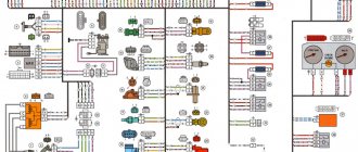
Instrument cluster block diagram
| № | Decoding |
| 1 | Electric power steering |
| 2 | Emergency gang control VAZ-2170 |
| 3 | Connection to oil pressure sensor |
| 4 | Parking brake indicator light |
| 5 | Electronic anti-theft device |
| 6 | Airbag control module |
| 7 | External lighting switch |
| 8 | Right turn signal indicator and doubler |
| 9 | Left turn signal indicator and backup |
| 10 | Engine control unit |
| 11 | Disabling the passenger's front airbag |
| 12 | Seat belt warning light |
| 13 | ABS brake system unit |
| 14 | Steering column switch button |
| 15 | Brake expansion tank indicator |
| 16 | ABS safety control module |
| 17 | Main beam headlight control unit |
| 18 | Shield backlight module |
| 19 | General disadvantage of the device |
| 20 | Constant positive battery terminals |
| 21 | Ignition switch contact |
| 22 | Fuel flow meter |
| 23, 24 | Steering wheel turn switches |
| 25,26 | Overboard temperature sensors |
| 27 | Fuel sensor VAZ-2170 |
| 28 | Speed sensor |
| 29 | Coolant temperature sensor |
| 30 | Tachometer signal |
| 31 | Shield diagnostics |
| 32 | Generator Regulator Relay Terminal |
Electrical connection diagram for heater wiring harness PRIORA 21723
- heater wiring harness block to the front wiring harness block;
- air mixing gearmotor;
- evaporator temperature sensor;
- electric fan 2172;
- speed controller;
- recirculation gearmotor.
Parking system sensor diagram 2172-3724248
1,2,3 – parking system sensors; 4 – block of the wiring harness of the parking system sensors to the block of the rear wiring harness.
Rear license plate light pinout
1. Supply voltage to the lights illuminating the rear number 2,3. Priora 4 license plate lamps. Electric trunk lid locking motor
Functionality check
Usually, many different and supposedly effective methods of checking using a tester or shorting a wire to ground are described. Alas, on a Priora there is only one 100% correct way to check the FLS. And this is done on the removed fuel pump module.
The description of removing this module is available in many articles and takes up a large amount of space. Therefore, we can only clarify that it is located under the rear seat of the Priora under a special hatch in the body. Above the gasoline tank.
Therefore, the transition to an already removed module.
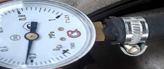
Therefore, the procedure is as follows. Disconnect the chip with wires from the module connector. Turn on the ignition. Wait for the fuel pump relay to operate. Use a test lamp to check the presence of current on the wire to the sensor.
Make sure that the fuel level sensor float is in its lowest position. Connect the wires. Wait 5 seconds. The gas tank reserve light on the panel should light up. Slowly raise the float to half its free stroke. The indicator arrow should accordingly show half the tank. Raise the float all the way. Accordingly, the arrow will show a full tank. This is with a working sensor.
If this does not happen, visually inspect the contact plate, wipe it and try again. If there are no changes. You can change the device.
Replacing the FLS
This is very easy to do with the module removed. The new unit is sold complete with a bundle of wires and connectors. You just need to disconnect the wires from the pump. Remove the chip from the inside of the module cover and, by snapping the two levers, remove the sensor plate up the wall. That's all, you can install a new one. And check its operation using the above method.
Video showing the device described in the topic:
Diagnostics and repair methods
To check and resolve problems, do some preparatory work:
- Look for the vehicle's service hatch, which gives access to the electric fuel pump lock and float mechanism. Usually located under the rear seat where the fuel tank is installed.
- Unscrew the mounting flange and pull the assembly out through the hole. Clean all contacts and the rheostat plate, and reinstall the unit.
- Prepare a “check” with a light bulb and a multimeter.
The first step is to accurately determine the “culprit” - check the sensor and pointer separately. The functioning of the device is diagnosed as follows:
- Turn on the ignition and connect one terminal of the multimeter or indicator to vehicle ground.
- Connect the second contact to the positive terminal of the wire going into the technological hole. The meter should show the voltage of the on-board network.
- Remove the positive terminal and short it to ground. If the instrument on the panel is working normally, the arrow will point to a full tank. This means that the fuel level sensor is not working.
- If 2 wires go to the gas tank, connect them alternately to the ground of the car. From one the indicator lamp should light up, from the second the pointer should move to maximum. If any of these symptoms occur, replace the sensor.
If there is a voltage of 12 volts on the wires, but after a short circuit to ground the arrow does not respond, you will have to disassemble the dashboard and remove the device. Similar actions are taken when the minimum gas remaining indicator does not work.
It is a little more difficult to independently check the updated system installed in cars of recent years; simply closing the terminals will not do anything. Using a multimeter, make sure that there is supply voltage on the wires, then you need to connect another working sensor to them. If the arrow on the dashboard reacts to the movement of the float, the element must be replaced.
Thorough cleaning of the slide and rheostat turns helps when the fuel gauge is trivial. The moving contact can be slightly bent so that it passes over the unworn part of the coils. Clean the potentiometer lead strips with a soft cloth moistened with alcohol to avoid damaging the cell surface.
Some gasoline sensor malfunctions can be fixed in the garage:
- a “sunken” float with a crack is replaced as an assembly with a lever or separately (depending on the make of the car);
- disconnected wires are connected using a regular soldering iron;
- the damaged rheostat plate is replaced with a new one if spare parts for your car are available.
At the moment, repairing the fuel level sensor is becoming irrelevant. Considering the cost of a new element, it is easier and more reliable to replace a non-working part.
If the indicator and remaining fuel counter work correctly, but the arrow on the device is not correct, try making adjustments. Carefully bend the float shaft in the desired direction and check the reading again. To achieve maximum accuracy, the operation will most likely have to be repeated several times.
Many owners of VAZ cars are faced with the problem of unreliable information about the remaining fuel. And, unfortunately, there may be several options for failure.
Faulty wiring, a failed fuel level sensor, or mechanical damage to the gas tank itself are the most common problems with this defect. If during the diagnostic process it turns out that the problem is in the sensor, it must be replaced.
In terms of the location of the fuel level sensor in the car, Priora inherited a similar position from its predecessors. Replacement consists of the following items:
1. Disassembling the fuel module
2. Removing and installing a new sensor
3. Install the fuel module
In a Priora car, the fuel level sensor is located in the fuel module, which also includes a fuel pump and a fuel filter.
The rear seat must be removed for disassembly. There is a small hatch underneath. Unscrew the two screws holding the hatch cover. The fuel module is located directly below it. Disconnect the retaining clip from the connector on the top of the module.
Then we disconnect the tees and fuel supply pipes. To do this, press the spring clips and disconnect. The fuel module is fixed with a pressure plate and screwed with 8 nuts. We unscrew them, then remove the spring washers and the wire going into the ground.
Then remove the pressure plate and the fuel module itself. At this stage you need to act very carefully, as there is a high probability of damaging the sensor float.
After disassembly, it was time to remove the faulty sensor. If the fuel level sensor in a Priora car fails, most likely the reason is that the contacts on the rheostat have become unusable. And this can only be solved by replacing the entire sensor. It is held on the fuel module body with only two clamps.
Before squeezing them and moving them towards the cover, you need to disconnect the wire from the fuel pressure regulator. Then you need to carefully remove the retainer from the module cover. You need to be very careful here, as the latter is quite fragile. It will be more convenient to disconnect it with a screwdriver. The sensor must be removed along with the accompanying cables. Install the new sensor in reverse order.
Before reinstalling the module, check that the rubber gasket and plastic O-ring are in the correct position. Please note that there is a slot in the spacer. It must be positioned so that the cut coincides with the protrusion of the fuel module cover. Then install the remaining parts in reverse order.
Please note that if the fuel level sensor fails, the Priora has a very obvious drawback: the fuel level needle does not move, no matter how much fuel is poured into the tank. Therefore, if the problem does not go away after replacing it with a new sensor, then most likely this is not the problem. In this case, it is necessary to check the integrity of the wires, as well as the condition of the contacts.
Since the process of replacing the fuel level sensor is quite labor-intensive, it makes sense to review other components of the fuel module. This should be done for both convenience and your comfort. Replace faulty parts if necessary. This extra work will save you time later.
What is the most unpleasant thing about the Priora engine fuel system? Right. There is no fuel level. This is monitored by a special sensor in the fuel tank. It's called a fuel level sensor. Present on all cars. But on vehicles with an ECM (electronic engine management system), this becomes especially important. Because. About this and the structure of this part in the article.
How to prevent the problem
It is almost impossible to prevent sensor damage, since mechanical wear of the sectors or float is an absolutely natural phenomenon. Therefore, if the indicator needle begins to behave strangely, and the check reveals problems with the sensor, it is better to replace it as an assembly, fortunately its price is not very high.
The same statement is true if the indicator itself breaks down. Service work to prevent damage to this device is not provided - only replacement if a malfunction is detected. Problems with electrical wiring, including a break in the wire leading from the fuel level sensor to the indicator, can also be solved by replacing the wire.
Source
Adjusting the readings
If the arrow periodically increases and decreases the values, then adjustment will help in this case.
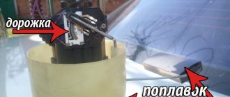
Adjusting the fuel sensor (FLS) - removing the fuel pump
- Raise the rear sofa.
- We remove the fuel pump and clean everything from dirt. (More information about removing the fuel pump here).
Preparing to remove the fuel pump
If in any position the arrow indicates incorrect values, then it is necessary to bend the adjusting tongues on this side so that the float rod can move to the right or left freely, depending on its location.
Adjusting the control arrow on the instrument panel
If the problem is the arrow on the instrument panel, then you need to remove the instrument panel and adjust it manually.