The cylinder head (cylinder head) is one of the most important components of the engine. The head of most modern engines contains a gas distribution mechanism, a partially manufactured combustion chamber, and channels for the lubrication and cooling systems through which working fluids circulate. In the event of certain malfunctions, it may be necessary to remove the cylinder head both to repair the head itself and the mechanisms inside it, and to gain access to parts and elements in the cylinder block (for example, the CPG).
We also recommend reading the article on how to properly tighten the cylinder head bolts when installing them on the engine. From this article you will learn about the features and sequence of tightening the cylinder head bolts, as well as various nuances when performing this procedure yourself.
The reasons why you have to remove the head can be different. Quite often, the cylinder head is dismantled as a result of engine overheating, in case of need to replace the cylinder head gasket or repair the timing belt. A frequent reason for removing the head is also the appearance of cracks in its body or the appearance of other defects. In such situations, the block head is removed for diagnostics on a test stand and then repairs are carried out. Quite often, engine modifications during minor tuning or deep boosting of the engine involve dismantling the cylinder head. Please note that this operation is considered quite serious and requires certain skills and special equipment. For this reason, we intend to further talk about how to remove the cylinder head yourself and do it correctly.
When is it necessary to repair the head?
Work on dismantling, repairing and installing the cylinder head in a car may be required for the following malfunctions:
- A white emulsion forms on the dipstick for diagnosing the level of motor fluid or under the plug for filling it. This indicates a breach of the cylinder head gasket or damage to the head housing (cracks) and refrigerant entering the lubrication system. The emulsion may be barely visible.
- Thick, white smoke began to come out of the car's muffler; drops of liquid could break out when the power unit was running. Most likely, this is a coolant and its entry into the exhaust system is associated with damage to the cylinders. The antifreeze level will be reduced, and the appearance of steam may be caused by overheating of the internal combustion engine and increased condensate content. But if white smoke comes out constantly, this indicates a broken cylinder head gasket.
- Oil stains or a greasy film have appeared on the surface of the antifreeze in the expansion tank; its presence may appear in the radiator unit. Engine fluid could get into the cooling system through cracks in the gasket or the block head itself. The exception is cars whose owners flush the cooling system with used motor fluids. Of course, this cannot be done.
- Small bubbles may get into the neck of the radiator device. This indicates that exhaust gases from the exhaust system flow from the combustion chamber into the cooling system. There is damage or a defect somewhere, most likely in the gasket itself or on the structure of the block head. If bubbles form when replacing consumables, this is normal. But if their formation is observed regularly, diagnostics of the power unit is required.
- Exhaust gases escape through a damaged gasket in the cylinder head. This problem is rare, but can be easily diagnosed. You just need to take a closer look.
- Engine fluid began to leak from under the cylinder head gasket. The problem may be poor tightening of the head screws. This procedure must be performed in a certain sequence, otherwise you can strip the threads and break the studs. The tightening process must be done using a torque wrench.
- If there is a gasket breakdown or the head is damaged directly between the cylinders, it will be difficult to determine. Signs of such a malfunction include an increase in fuel consumption and a drop in power of the power unit. The problem may be accompanied by a decrease in compression in one or more cylinders, usually this occurs in neighboring devices.
The “ICE Theory” channel spoke in detail about the need to repair the cylinder head.
Cracks in the block
If there are cracks between the cooling jacket in the engine and the oil channels, then this is the most serious defect that you can encounter. If a used part is selected to replace the cylinder block, it must also be carefully examined for deformations.
Even minor microcracks will cause the coolant to mix with the oil. Damage between the cooling system jackets and the cylinder walls will certainly lead to the appearance of antifreeze in the combustion chamber.
Microcracks can form from overheating, as well as due to casting defects. The cast block may have pits and other defects. In the case of the cylinder head, this is also a replacement of the VAZ cylinder head.
Process
Before proceeding with the removal and repair of the VAZ 2109 cylinder head, it is necessary to carry out some preparatory work in accordance with the order.
Removal
- First of all, remove the air purifier housing.
- Disconnect the hoses and wires from the carburetor or injector.
- Next, you need to disconnect the pants from the manifold.
- We remove the distributor.
- Unscrew the valve cover.
- Remove the carburetor and manifolds.
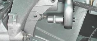
- To unscrew the head bolts on a VAZ 2109, you will most likely need a wrench and a hexagon, because the bolts are tightened with decent force.
Pipe as a lever
Remove the head mounting bolts with washers.
We take out the bolts
- We remove the VAZ 2109 cylinder head from the power plant unit.
- We remove the gasket.
Gasket that has expired and needs to be replaced
Also, if necessary, we carry out repairs or modifications to engine block components.
Tuning
Qualified adjustment, modification and tuning of the VAZ 2109 head will help to fully reveal the capabilities of your power unit. You've probably heard a lot about this, read or even watched videos on the Internet. Typically, when tuning, the channels are bored and smoothed, thereby reducing the turbulence that reduces power. The valves are changed to larger ones and ground into the seats. Tuning may also involve replacing standard valve guides with bronze ones.
Valve lapping
Lapping control is carried out as follows:
- the assembled head lies on its side;
- liquid is poured into the collector holes (ordinary water can be used).
If the liquid does not flow through the valves, this means that the work was done efficiently and the valves were ground in correctly. After all faults have been eliminated, you can begin installing the head.
Installation
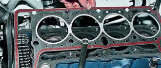
Begin assembly by installing a new gasket
Attention! The holes in the gasket must coincide with the guides, which are located at the corners of the block
New gasket
- You need to install the head carefully, do not move the gasket from its place at this moment.
- We insert the bolts into their places and begin tightening with a torque wrench.
Tightening with a torque wrench
Next, we install the dismantled equipment, injector or carburetor, in reverse order. Fresh coolant is added. Wires and hoses are connected.
Attention! This operation requires some knowledge and skills. Therefore, before performing it, you should know that the bolts need to be tightened according to a certain pattern and with a certain force
It would be useful to read additional material on this topic and watch video instructions.
How to remove the reel and replace the line
Trimmer owners, mostly newbies, are confused, bordering on panic, when it becomes necessary to change the cutting tool or the line in the reel. Very often, when trying to unscrew the mower head, users simply render it unusable, unaware that it is unscrewed in the opposite direction. To avoid this, if you need to change tools, it is recommended that you read the step-by-step instructions below.
- Before securing the line in the reel, turn off the motor engine or disconnect the electric trimmers to avoid injury that could occur if the cutting tool is accidentally started.
Unscrew the cap attached to the transfer shaft. To do this, the shaft must be fixed by aligning the holes on the washer and on the shaft and inserting a metal rod or screwdriver into them.
Unscrew the nozzle. You should know that the thread is left on the shaft. Therefore, turn the trimmer coil to the right, that is, clockwise. Disassemble the mower head. Most often, the head cover is attached to fasteners. To remove it, you need to secure these clips into the case by squeezing the edges of the cover. In case your trimmer is equipped with a semi-automatic mower with a button at the bottom, the nozzle should be removed carefully, as you can lose the spring, which sometimes flies out when removing the cover.
Cut the required amount of fishing line. Typically its length is 5 meters. Use cord with the diameter specified in the tool's instructions. It is not recommended to exceed the maximum line diameter, as this will increase the load on the engine and increase gasoline consumption.
Find the middle length of the cord and fold it in half. You will have a cycle. Special grooves are cut inside the coil (there may be holes). Insert a loop from the line in this groove.
Insert the line onto the reel by turning it counterclockwise. The cord filling should be as flat as possible, the coils should be laid without overlap and with good tension. When the winding is finished, leave free ends of the line about 20 cm long and fix them in the grooves on the sides of the coil.
Assemble the sliding head. Before finally assembling the nozzle, do not forget to insert the spring and washer (if it exists). Place the reel in the housing and thread the ends of the cord through the holes or tabs.
Attach the cover and secure it with the latches.
Screw the nozzle back onto the gear shaft and secure it with a screwdriver. To twist the trimmer coil, it will be to the left (counterclockwise).
How to control the quality of work?
To ensure the quality of the work done, be sure to check the tightening torque (use a torque wrench for this).
When doing the job, you must wait until the bolt reaches its “yield point.” It's easy to diagnose. Once you set the required tightening torque, it will not change.
In doing so, keep two important points in mind. If you increase the torque to a level of 20 kgcm, but the bolt does not turn, then it needs to be changed.
The reason is too much strength. If it is impossible to tighten the bolt and the torque decreases all the time, then it should also be replaced.
Stages
- The cylinder head mounting bolts should be tightened using a torque wrench with the tightening torque specified in the VAZ 2106 operating instructions.
- Next, we reassemble in reverse order. At the same time, we control the coincidence of the marks and adjust the belt tension. The valves should also be adjusted.
- After final assembly, you need to check the operation of the engine.
This completes the replacement of the gasket on the VAZ 2106.
There is nothing complicated in the procedure; a car enthusiast can do it independently, even with little experience in repair work. This way you can save on car service costs.
Diagnostics
There shouldn't be any problems installing the new gasket. But repairs can sometimes be difficult for inexperienced mechanics. Let's consider the main options for diagnostic work:
- The most basic check is to determine the plane adjacent to the block. It often bends under the influence of high temperatures, in other words, from overheating. To do this, apply an iron ruler edgewise to the plane, after which the gap is checked using a feeler gauge. If it exceeds 0.1 mm, then it is better not to use this part anymore;
- Perform a visual inspection. This makes it possible to identify mechanical damage, such as cracks;
- Check the condition of the valves. First of all, they look at the condition of their saddles. If there are scratches, then it is best to grind the valve. In case of severe damage, they are replaced. At the same time, they look at the condition of the valve springs. To remove the valves, you will have to purchase a special puller. If they are suspected of increased wear, new ones are installed.
Inspection, troubleshooting and repair
Valve seat profile for engines mod. 402 and 4021
A - intake valve seat;
B - exhaust valve seat
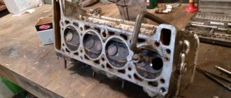
1. After disassembling the cylinder head, wash all parts in gasoline, wipe and dry. Clean the combustion chambers from carbon deposits.
2. Inspect the block head. If there are cracks on the bridges between the valve seats or on the walls of the combustion chambers, or signs of burnout, replace the cylinder head.
3. Using a metal ruler and feeler gauges, check whether the flatness of the surface of the head adjacent to the block is broken.
To do this, place the ruler with its edge on the surface of the head, in the middle along, and then across, and use feeler gauges to measure the gap between the plane of the head and the ruler.
If the gap exceeds 0.1 mm, replace the head.
4. Inspect the valves. If cracks, warping of the valve head, burnout, or deformation of the stem are detected on the working face of the valve, replace the valve.
Minor marks and scratches on the working face of the valve can be removed by lapping.
5. Check the condition of the valve springs. Replace bent, broken or cracked springs.
6. Check the condition of the valve seats. There should be no signs of wear, holes, corrosion, etc. on the working chamfers of the seats.
Minor damage (small marks, scratches, etc.) can be removed by grinding the valves. More significant defects can be removed by grinding.
When grinding, maintain the seat dimensions indicated in the figure. After grinding, check the runout of the seat chamfer relative to the hole in the valve guide; the maximum permissible runout is 0.05 mm.
After grinding the seats, grind the valves. Then thoroughly clean the block head and blow it with compressed air so that there are no abrasive particles left in the channels closed by the valves and in the combustion chambers.
7. Check the gap between the guide bushings and valves. The clearance is calculated as the difference between the diameter of the hole in the bushing and the diameter of the valve stem.
The maximum permissible gap is 0.25 mm. If the gap exceeds the specified value, the valve and guide sleeve must be replaced.
The old bushing is pressed out using a mandrel from the side of the combustion chamber.
Before installation, new bushings must be cooled in carbon dioxide (“dry ice”), and the block head must be heated to 160–175 ° C.
Then insert the bushing into the cylinder head so that it protrudes from the valve spring side above the cylinder head by 20 mm.
The bushing should fit into the head freely or with little force.
After installation, expand the hole in the bushing to a diameter of 9.0 +0.022 mm.
Then grind the valve seat, centering the tool on the hole in the bushing.
8. You can check the block head for cracks as follows. Connect a compressed air hose to one of the holes in the cooling jacket.
Plug all holes in the block head with wooden plugs. Lower the head into a bath of water and apply compressed air at a pressure of 1.5 atm. Air bubbles will emerge where cracks form.
9. Clean with wire and blow out with compressed air the holes in the rocker arm axle, in the rocker arms and in the adjusting screws.
Check the tightness of the bushings in the rocker arms. If the bushing does not fit tightly, it needs to be replaced, since during engine operation it can turn and block the hole for supplying oil to the pusher rod.
Assembly
Assemble the block head in the reverse order of disassembly. Before installation, lubricate oil seals, valve stems and valve rocker shafts with engine oil.
Install the valves in accordance with the marks made during disassembly.
Install the gasket of the thermostat housing and the gasket of the rear cover of the block head with a Hermesil type sealant.
Installation
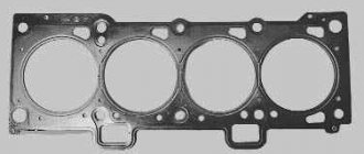
When installing the cylinder head, it is recommended to replace the cylinder head gasket.
The cylinder head is installed in the reverse order of removal.
Tightening torque 83–90 Nm (8.3–9.0 kgf m). After installing the cylinder head, adjust the clearances in the valve drive.
Install the block head in the reverse order of removal.
Tighten the cylinder head fastening nuts in two stages:
Stage 1 - 40–60 Nm (4.0–6.0 kgf m);
Stage 2 - 83–90 Nm (8.3–9.0 kgf m).
Problems when paying with bank cards
Sometimes difficulties may arise when paying with Visa/MasterCard bank cards. The most common of them:
- There is a restriction on the card for paying for online purchases
- A plastic card is not intended for making payments online.
- The plastic card is not activated for making payments online.
- There are not enough funds on the plastic card.
In order to solve these problems, you need to call or write to the technical support of the bank where you are served. Bank specialists will help you resolve them and make payments.
That's basically it. The entire process of paying for a book in PDF format on car repair on our website takes 1-2 minutes.
If you still have any questions, you can ask them using the feedback form, or write us an email at [email protected] .
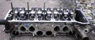
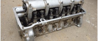
What does the cylinder head consist of?
The cylinder head is an engine unit into which many different, equally important parts are installed. In general, as far as the design of the internal combustion engine is concerned, there is no such thing: this is an important detail, but this is not important. Each part has its own functions and affects the operation of the motor.
Design of the cylinder head assembly
- Cylinder head.
- Cylinder head gasket.
- Valve guide bushing.
- Oil deflector.
- Cylinder head cover gasket.
- Cylinder head cover.
- Power strip.
- Plug for filling oil into the internal combustion engine.
- Cylinder head bolt.
- Cylinder head cover mounting stud.
- Cylinder head cover nut.
- Front cylinder head cover gasket.
- Stub.
Cylinder head device:
- One or more camshafts.
- Combustion chambers.
- Mounting points for the gas distribution mechanism (GRM).
- Cooling system jacket.
- Channels through which liquids circulate and gases are removed.
- Channels for supplying engine oil.
Installation
So, before us is the opened head of the block. All we have to do is remove the old gasket and install a new one in its place
It is important to thoroughly clean the contact surface. If this is not done, oil will leak through small channels into the adjacent chamber and mix with antifreeze.
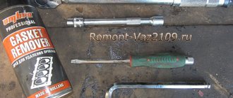
Experts recommend using a special spray.
It’s called “to remove gaskets.” Its cost is about 400 rubles. A volume of 300 ml is enough for several doses. Instructions for use are quite simple. It is necessary to apply the spray to the surface of the block and after ten minutes, remove the remaining element with a clean piece of rag.
The new gasket already has red silicone sealant on it. All we have to do is install it in its rightful place. Using two guides, we center the element in the block. Now all that remains is to assemble the engine.
Types of cylinder head gaskets
Manufacturers of automobile engines use the following types of sealing elements:
- Asbestos. The products are characterized by high heat resistance, sufficient elasticity and resilience. Typically included in repair kits.
- On an asbestos-free basis. Less practical than the above - small shrinkage coefficient, limited service life.
- Metal. They are rightfully considered the best sealant option. It ensures the most uniform distribution of pressure around the perimeter and the fit of the joining planes.
Important! When choosing a sealing element for the cylinder head, it is not recommended to save money - disassembling the engine only to replace it, as a result of premature wear, is more expensive than immediately installing an expensive but high-quality product.
This is interesting: Frequency of engine oil changes - determine the timing and learn how to change it yourself
What is needed to replace the cylinder head?
It is necessary to disassemble, replace and restore the cylinder head on an 8-cylinder or other engine after preparing the tools:
- a special mandrel will be required for pressing oil seals;
- micrometer, necessary for measuring valves, as well as guide elements;
- reamer, will be used to unfold new bushings;
- special mandrels for dismantling (pressing out) and installing new bushings;
- a set of countersinks, designed to restore valve seats;
- special devices for desiccation of valve spring elements;
- set of wrenches;
- new cylinder head gasket;
- an electric stove is used for heating if it is to be troubleshooted, as well as for warming up the bushings before pressing.
Before repairing the cylinder head, it is imperative to prepare the necessary spare parts and tags; their composition depends on the car model and the type of defect.
User Alex ZW talked about repairing the cylinder head, as well as what is required to complete this task.
https://youtube.com/watch?v=XPt_bXDCR6s
Preparing tools
Preliminary preparation of all necessary tools will save time when dismantling the mechanism. To remove you will need:
- Flathead screwdriver.
- Knife.
- Containers for coolant and engine oil.
- Wire cutters.
- Pliers.
- Hammer.
- Socket wrenches.
Experts also recommend having a torque wrench. The tool is mainly used only when installing the cylinder head, but sometimes it may be needed when removing it. Since all car models have their own characteristics, it is better to find a manual for a specific car in advance.
Causes of defects
The purpose of the head is to form a combustible mixture of air and fuel, which is created in the combustion chambers. It is used to ignite and propel the vehicle. The cylinder head, like any other machine component, is not immune to defects. Malfunctions can occur spontaneously or as a result of a traffic accident or wear and tear of the unit.
All failures are associated with:
- defects in the production of the cylinder head;
- high load on the node;
- incorrect or insufficient maintenance;
- poor quality lubrication of the internal components of the device;
- lack of protection against freezing or corrosion in the refrigerant circuit.
Signs of a broken cylinder head gasket
Prerequisites for checking the condition of the gasket are presented:
- traces of engine oil or antifreeze are visible on the perimeter of the junction of the head and the engine base;
- when checking the oil, there is a light foamy coating on the dipstick, indicating that cooling liquid has entered the crankcase;
- light thick smoke from the exhaust pipe, after warming up the internal combustion engine, also informs about the presence of antifreeze in the crankcase;
- grease stains in the cooling expansion tank or radiator indicate oil leakage into the cooling system.
Important! If, during inspection, one or more signs are identified, it is necessary to take measures to identify the causes, and possibly replace the gasket. Otherwise, the consequences will entail a major overhaul of the engine.
What does a breakdown in the cylinder head gasket lead to?
Operation of a vehicle with a damaged sealing element is presented as follows:
- the car will have difficulty starting, and during operation it may smoke and traction will deteriorate;
- the engine will stall during operation, and its speed will be unstable;
- compression may be lost in the cylinders;
- If the engine oil is diluted with antifreeze, the internal parts will “grind” each other.
As a result, a visit to a service station is guaranteed to replace parts and assemblies that have fallen out of working order.
Cylinder head, valve drive
Timing belt
- Lower toothed belt guard (various designs; to remove, unscrew the bolt and remove the vibration damper).
- Bolt (tightening torque: 10 Nm).
- Bolt (tightening torque: 10 Nm).
- Bolt (tightening torque: 20 Nm).
- Upper toothed belt guard (various designs; when installing, carefully align with the lower toothed belt guard).
- Toothed belt (before removing, mark the direction of rotation with chalk or a marker).
- Bolt (tightening torque: 25 Nm).
- Nut (tightening torque: 10 Nm).
- Washer.
- Bolt (tightening torque: 100 Nm; to loosen and tighten, hold with counter support 3036).
- Tension roller (various designs).
- Camshaft sprocket.
- Toothed belt protection (various designs).
- Nut (tightening torque: 10 Nm).
- Bolt (tightening torque: 20 Nm).
- Segment key (ensure tight fit).
- Rear toothed belt guard (various designs).
- Tensioner roller installation bolt (tightening torque: 25 Nm).
- Intermediate sprocket (mark the correct installation position; the narrow jaw of the sprocket should be directed outward, and the TDC mark of the first cylinder should be visible from the front).
- Crankshaft sprocket (the contact surface between the sprocket and the crankshaft must be free of oil; can only be installed in one position).
- Crankshaft sprocket bolt (tightening torque: 90 Nm + another ¼ turn (90°); replace with a new one after each removal; do not apply oil to the threads; use counterhold 3099 for loosening and tightening).
- Intermediate sprocket bolt (tightening torque: 100 Nm; use counter support 3036 to loosen and tighten).
- Toothed belt tensioner (various designs).
- Bolt (tightening torque: 10 Nm).
Removal
1. Remove sound insulation -arrows-.
2. Remove the generator drive belt (see the corresponding section above).
3. Remove the upper toothed belt guard -arrows-.
4. Mark the direction of rotation of the timing belt with chalk or a marker.
5. Align the crankshaft to the TDC mark of the piston of the first cylinder -arrows-, turning it by the central bolt of the pulley in the direction of normal engine rotation.
Note
At the same time, the mark on the front of the camshaft sprocket must align with the mark on the toothed belt guard -arrows-. If the marks do not match, turn the crankshaft one more full turn.
6. Unscrew the vibration damper bolts.
7. Unscrew the bolts of the lower toothed belt guard -arrows-.
Installing a timing belt on an Alfa Romeo Twin Spark
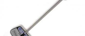
- Make sure that the piston of the first cylinder is at TDC. Use the dial indicator (5).
- Hold the camshafts with wrenches (9) and (10), loosen the bolts securing the timing pulleys.
- Except 147: Remove the third bearing caps of both camshafts, pos. (11) and (12).
- 147: Remove the second bearing cap (16) for the intake camshaft and the third bearing cap (17) for the exhaust camshaft.
Note: Before removing, mark the bearing caps for proper installation.
- In place of the covers, install the camshaft clamps (11) and (12) or (16) and (17).
Note: To prevent damage to the shaft, ensure complete alignment of the cam and the cam slot in the retainer.
- Install the belt in the following order: Crankshaft.
- (A) except 147:100-124 Nm.
- Indicator (5).
- Except 147: 13-16 N m.
- (A) except 147: 21 - 26 Nm.
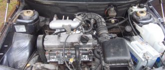
Malfunctions when removal and installation of the cylinder head are required
There are a number of malfunctions due to which the cylinder head of the VAZ “six” has to be removed from the car for further diagnostics or repairs. Let's look at them in more detail.
Gasket burnt out
The following signs indicate that the cylinder head gasket has failed (burnt out or was punctured):
- the appearance of leaks or gas breakthrough at the junction between the engine block and the head. With this phenomenon, extraneous noise appears in the operation of the power plant. If the outer shell of the seal ruptures, traces of lubricant or coolant may appear;
- formation of an emulsion in motor oil. This happens when coolant gets into the oil through the gasket or when a crack forms in the BC;
- the appearance of white smoke from the exhaust system. White exhaust occurs when coolant enters the combustion chamber of the engine. In such a situation, the liquid level in the expansion tank gradually decreases. Untimely repairs can lead to water hammer. Water hammer is a malfunction that is caused by a sharp increase in pressure in the sub-piston space;
- entry of lubricant and/or exhaust gases into the engine cooling system. You can detect whether lubricant has entered the coolant by the presence of oil stains on the surface of the liquid in the expansion tank. In addition, when the seal of the gasket is broken, bubbles may appear in the tank, indicating that exhaust gases have entered the cooling system.
Video: Damage to the cylinder head gasket
Damage to the cylinder head mating plane
The following reasons can lead to the formation of defects in the mating surface of the block head:
- long-term operation of the power unit;
- motor overheating;
- poor quality coolant.
Defects of this kind are eliminated by processing the plane, with preliminary dismantling of the head.
Damage to the mating plane using the example of the Kalina cylinder head
Cracks in the block head
The main reasons that lead to the appearance of cracks in the cylinder head are overheating of the engine, as well as improper tightening of the mounting bolts during installation. Depending on the nature of the damage, the head can be repaired using argon welding. In case of serious defects, the cylinder head will have to be replaced.
Overheating of the engine can lead to a crack in the cylinder head.
Wear of guide bushings
With a high mileage of the engine or the use of low-quality engine oil, the valve guides wear out, which leads to a violation of the tightness between the seat and the valve plate. The main sign of such a malfunction is increased oil consumption, as well as the appearance of bluish smoke from the exhaust pipe. The problem is resolved by replacing the guide bushings.
Valve seat wear
Valve seats can wear out for several reasons:
- use of low quality fuel;
- long engine mileage;
- Incorrect ignition setting.
The malfunction can be solved by straightening or replacing the saddles. In addition, the ignition system must be checked.
Seat defects lead to a loose valve fit and loss of combustion chamber tightness.
Broken spark plug
Quite rarely, but it happens that as a result of over-tightening the spark plug, a part breaks off on the thread in the spark plug hole. To remove the remains of the cylinder head spark plug element, you need to dismantle the threaded part and unscrew it using available tools.
CPG malfunctions
If there is a problem with the cylinder-piston group of the engine, the cylinder head also has to be removed. The most common failures of the CPG include:
- increased wear of cylinders, rings and pistons;
- piston damage;
- occurrence of rings.
If the cylinders are worn excessively, the engine is completely disassembled to replace the piston group, as well as to bore the internal cavity of the cylinders on a machine. As for the damage to the pistons themselves, although they rarely burn out. All this leads to the need to dismantle the cylinder head and replace faulty parts. If the rings are stuck, normal operation of the cylinder and the engine as a whole becomes impossible.
If the rings are stuck, normal engine operation is disrupted
DIY cylinder head repair
To carry out repairs, you will have to disassemble the cylinder head. Conventionally, the diagnostic and troubleshooting procedure can be divided into several stages.
First stage
Checking and repairing the cylinder head at the initial stage is carried out as follows:
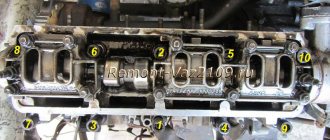
- The two fastening nuts are unscrewed and the device is dismantled. The nut securing the bracket for the supply line of the water pump mechanism is unscrewed several turns. The bolt that secures the fuel pipe holder is removed, and the device itself is removed. Then you need to unscrew three more nuts that secure the receiver device, as well as two that secure the bracket. The latter is removed after the actions are completed.
- It remains to unscrew two more nuts that secure the receiver; a wrench is used for this. The tightening of the nut for fixing the bracket of the receiver device is loosened. The unit itself is then dismantled. The nuts securing the bracket and the intake manifold are unscrewed, and both parts are removed. You also need to unscrew the fastenings of the exhaust manifold device and dismantle the unit.
- Carefully remove the two gaskets on the intake manifold and exhaust manifold. These items must be replaced even if their condition is generally satisfactory. Then the cylinder head must be placed so that the housings of the bearing elements are directed upward. Wooden spacers are pre-installed under the assembly, this prevents damage to the valves.
- Two nuts, as well as a screw that secures the rear cylinder head cover, are unscrewed, after which it is removed. There is a rubber seal under the head of the fastening element. Using a spark plug wrench, unscrew the spark plugs. Then you need to evenly unscrew the ten nuts securing the fastenings of the front and rear housings of the camshaft bearing elements. The washers, as well as the housings themselves, are dismantled.
- If the key in the camshaft groove is not installed tightly, it must be removed. Then the timing pulley block is dismantled from the cylinder head, and the oil seal is removed from the assembly. The valve pusher elements with adjusting washers are removed. After removing the next pusher, it is necessary to mark each element and the washer that secures it with numbers. This will avoid mistakes during further installation. There is no need to remove shims from devices unnecessarily.
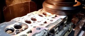
- The combustion chambers are cleaned from traces of carbon deposits, for this you can use acetone or fuel, the residues are subsequently removed. A visual diagnosis of the cylinder head is performed. If there are defects in the form of cracks or traces of burnout in the chambers, the device is completely replaced; its repair is impractical. It is necessary to remove burrs if they are present on the surface of the cylinder head.
- The work plane, which is adjacent directly to the block, is diagnosed. To complete the task, you need to place the ruler edge-on on the surface itself and measure the gap, first along the diagonals, and then along. If the size of the play is more than 1 mm, the cylinder head is replaced with a new one. To diagnose the tightness of the device, you need to unscrew the two nuts that secure the exhaust line of the cooling system. The hose itself is then removed.
- Then you need to plug the hole in the engine cylinder head under the exhaust line. To do this, you can use a dry cardboard gasket, after installing which the fixing nuts are tightened.
- Then fuel or kerosene is poured into the channels of the water jacket. If the fluid level decreases after filling, this indicates the presence of cracks and the need to replace the cylinder head. When the diagnosis is completed, the cardboard gasket is removed.
- The condition of the bearing surfaces under the pulley journals on the cylinder head and bearing housings is diagnosed. If the inspection shows traces of defects or scoring as a result of wear, the head is replaced along with the bearings.
User Alexander Skripchenko in his video, using the example of a VAZ 2108 car, showed what mistakes should not be made when performing cylinder head repairs.
Second stage of repair
At the next stage of repair, the following actions are performed:
- The oil system channels are flushed. To perform this task, it is necessary to plug the hole located on the side of the combustion chamber; it is located between the third and fourth cylinders. Then fuel is poured into each channel; you need to wait about twenty minutes to remove contaminants. After this, the fuel is drained and the plug is dismantled. Then you need to finally flush the channels with fuel using a blower or compressor.
- To diagnose valve tightness, fuel or kerosene is poured into the combustion chambers. If within three minutes after filling the liquid does not leak out, then the valve elements are intact and do not need to be replaced. When the kerosene begins to come out, the parts are ground in.
- A support, for example, a bearing, is installed under the valve being dismantled. A device is installed to compress the spring elements of the parts, after which they are compressed. Using a screwdriver or tweezers, the so-called crackers are removed. Then the upper plate of the spring element, as well as the devices themselves, are removed. In the same way, crackers, springs and plates are removed from other valves.
- Then you need to mark the valve elements in accordance with the cylinder numbers. By pushing these parts from below, you need to remove them from the cylinder head. The valve stem seals are removed using pliers or a special device. Then the lower plates of the valve spring elements are removed. The latter are cleaned from traces of carbon deposits using a metal brush, after which they are visually diagnosed.
- Valves must be replaced if they have deep defects or scratches on the working surface. Devices with cracks, deformed rods, plates, or burn marks must be replaced. If the damage on the surface is shallow, then the situation can be corrected by grinding in. When this method does not solve the problem, parts are polished using a special machine. When performing this task, it is imperative to maintain the overall dimensions; each car manufacturer has their own.
- The condition of the valve seats is diagnosed. Their surfaces are not allowed to show signs of wear, corrosion, etc. Seats can only be replaced by specialists; if the defects are not serious, they are corrected by grinding in. Significant damage can only be removed by sanding. When performing a task, it is important to maintain the dimensions so that the ground devices can be used.
- At the next stage, the condition of the external and internal spring element of the valve is diagnosed. Parts must be replaced if they are worn, broken, bent or have cracks. To diagnose the elasticity of the external spring element, its height is measured, first in a free state, and then under load. The internal part is checked in the same way. If the checked elements do not meet the required values, they must be replaced.
The channel “ICE Theory” spoke in detail about the repair procedure and assembly of valve elements of the cylinder head.
Third stage
Algorithm of action when performing the final stage of diagnostics and repair:
- The valve pusher elements are checked. If there are defects in the form of scratches and burrs on the working surface of the device, they must be replaced. Damage to the adjusting washers is also not allowed. We are talking about wear, scratches, scuffing, etc. Otherwise, the parts must be replaced with new ones. On the surface of the washers there may be concentric marks of running-in, which appeared as a result of impact with the camshaft cams.
- The gaps between the valve elements and guides are checked. The nominal amount of play for inlet devices is from 0.022 to 0.055 mm, for inlet devices - from 0.029 to 0.062 mm. The value of the maximum permissible gap for both types of parts varies in the range of up to 0.3 mm. The backlash itself is directly defined as the difference between the diameter of the hole in the bushing and the valve element stem. It is better to carry out diagnostics in a workshop, since the test will require a special device - a bore gauge.
- If the gap is less than the maximum permissible value, then to eliminate it you can resort to replacing the device. Otherwise, you will have to change the guide sleeve. To perform this task, it is necessary to press out the defective element from the side of the combustion chamber; a special mandrel is used for this. Spare parts are supplied with bushings equipped with retaining rings. The outer diameter of such a part is larger, and the size of the hole for installing the valve element is smaller.
- The bushing is installed using the press-fit method from the camshaft side; it must first be treated with engine fluid. The part is installed until the lock ring stops in the cylinder head. The hole in the bushing is unfolded using a special reamer. For intake elements it must be increased to approximately 8.022-8.040 mm, and for exhaust elements - to 8.029-8.047 mm.
- If you are installing an old part, you must first remove burrs from its surface. After completing the task, grinding the valve element to the seat is required. The element is installed in the cylinder head, taking into account the previously indicated markings. Before installing the part, its rods must be treated with motor fluid. The lower plates of the spring elements are being installed.
- The oil seals are being installed.
- The camshaft is checked; this unit must be replaced if there are signs of wear on its journals or cam surfaces in the form of large marks or scuffs. In workshops equipped with specialized tools, it is possible to diagnose the radial runout of the camshaft journals; this value should be no more than 0.02 mm. It is also necessary to check the play between the support holes, as well as the pulley journals; this value will ideally be no more than 0.2 mm.
- The camshaft is installed together with the bearing element housing.
- A new cylinder head gasket, exhaust manifold, and intake manifold are being installed. Under the nuts that secure this hose and manifold, there are larger nuts compared to the other fastening elements.
The user Autoreanimator spoke in more detail about replacing and installing a new cylinder head gasket.
Assembly, preparation for starting the engine
Assembly is carried out in reverse order
Install a new valve cover gasket Install a new timing belt Check the marks Assemble the timing case Alternator belt, power steering belt All connectors, both coolant flanges, gasoline hoses, air tubes Fill with coolant
Turn the starter on the engine a couple of times with the explosive coil disconnected.
We start the engine... Immediately after starting the engine, the hydraulic compensators may knock, but the knocking quickly goes away.
Volkswagen Technical Site 1999-2017 Volkswagen Technical Site (VWTS)
How can I find the information I need here?
Decoding the factory equipment of the car (English) Decoding the factory equipment of VAG in Russian! Diagnostics of
Volkswagen, Audi, Skoda, Seat, error codes.
If you have not found information on your car, look at the cars built on the platform of your car. Most likely, the information on repair and maintenance will be suitable for your car.
GAZ 2004, 136 l. With. - spare parts
Belokurikha
GAZ 3110 Volga, 2000
50 000 ₽
Toguchin
GAZ 31105 Volga, 2006
128 000 ₽
Novosibirsk
GAZ 3110 Volga, 1998
50 000 ₽
Ekaterinburg
GAZ 3102 Volga, 2005
90 000 ₽
See more cars on Drome
Participate in the discussion can only registered users.
Login Register