The ability to reliably block the engine from starting in the event of an alarm is necessary for the alarm system. Another thing is that it is not so easy to block the engine correctly: by modern standards, it is considered necessary for the car thief to spend at least half an hour bypassing the protective circuits. Therefore, it is not without reason that it is said that an alarm installer must think like a thief: when installing an alarm, the first question he asks himself is “how can it be turned off or bypassed?”
Blocking via CAN bus
However, on modern cars there is an even more elegant way to block the engine from starting. In this case, there are no physically broken circuits, and there are no additional connections: it is enough for the alarm to have a connection with the car’s CAN bus.
The essence of such blocking is that when an alarm is triggered, the alarm transmits a blocking command via the bus and repeats it all the time until the alarm goes off. And until the thief turns off the central unit, attempts to start the engine will be useless. If we take into account that with proper installation of the central unit, half of the interior will need to be disassembled to remove it, then this method is clearly the leader in terms of efficiency. At the same time, there is no reason to fear reliability: the blocking relay can break, the contacts can oxidize, and this blocking is exclusively virtual and appears only when needed.
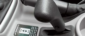
How do you know if your car can be locked via CAN bus? For StarLine systems, just go to can.starline.ru and select your car model to get an available list of CAN functions for it. In it we are interested in “Engine blocking” and “Engine start prohibition” - in the first case, the check mark opposite means that the alarm is capable of turning off a running engine, in the second - preventing it from starting.
How to program important options
Important alarm options include the following:
- alarm key fob battery saving mode;
- car engine temperature control;
- remote engine start.
The key fob programming guide goes through the following steps:
- The ignition key is set to the on position without starting the car engine.
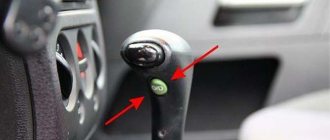
- It is necessary to press and hold the button on the override alarm key fob.
- After six beeps, the button is released to the off position.
- Buttons two and three should be pressed until a certain sound signal is heard.
- Turn off the ignition, everything is ready.
Installation process
- We prepare the wiring. We crimp the connectors.
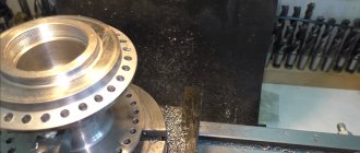
- The new VAZ 2110 starter relay must be mounted under the hood in a place so that it is definitely not flooded with water from puddles and rain. Many specialists install the relay on the stud of the washer reservoir.
- We bring the wire from the relay to the starter and connect it to the place of the red wire (it is with the “dad”). This is the connection point for the traction relay. This way we energized the coil of the new relay.
- We put a new wire with an 8 (mm) ring connector onto the positive terminal of the starter and tighten it tightly with a bolt. This wire goes to pin 87 in the new relay. I hope the VAZ 2110 starter connection diagram is clear to everyone.
- From the new relay on pin 30 we pull a wire with a “female” connector to the starter, to the place where the traction relay is connected.
- We connect the lead from pin 85 on the new relay to ground.
- We cover all wiring with a corrugated sleeve and thoroughly insulate it so that the wiring and contacts are not exposed to moisture.
- We do a test drive.
That's it, the additional VAZ 2110 starter relay (diagram attached) has been successfully installed.
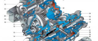
VAZ 2106 starter connection diagram
- starter;
- generator;
- accumulator battery;
- pull-in winding of the traction relay;
- ignition switch;
- traction relay holding coil
| 1 – drive side cover; | 14 – relay cover; |
| 2 – retaining ring; | 15 – contact bolts; |
| 3 – restrictive ring; | 16 – collector; |
| 4 – drive gear; | 17 – brush; |
| 5 – overrunning clutch; | 18 – armature shaft bushing; |
| 6 – drive ring; | 19 – cover from the collector side; |
| 7 – rubber plug; | 20 – casing; |
| 8 – drive lever; | 21 – shunt coil of the stator winding; |
| 9 – relay anchor 2106; | 22 – body; |
| 10 – holding winding of the traction relay; | 23 – stator pole fastening screw; |
| 11 – pull-in winding of the traction relay; | 24 – anchor; |
| 12 – relay coupling bolt; | 25 – armature winding; |
| 13 – contact plate; | 26 – intermediate ring. |
Starter for tractors Belarus MTZ 82(80)
The power unit in the electric starting system is the starter. Depending on the type of starting system on the MTZ 82 tractor, electric starters are used both to start the PD 10 starting engine and directly to start the diesel engine. As for the starter start of the launcher, we note that they use units of the ST 352 D, ST 362A brands with a power of 0.6 hp. The article will focus on the components installed for electric starting of a diesel engine: their varieties and technical characteristics, advantages and disadvantages, causes of operational problems, features when choosing and purchasing a component.
Hidden control relay
The disadvantage of relay interlocking is obvious - you have to pull the control wire from the central unit to the connection point, and it needs to be hidden in standard harnesses. Having found this wire, the thief will be able to use it to trace both the location of the relay and the location of the central alarm unit.
To avoid this, complex electronic relays are used, controlled both via a radio channel (as in StarLine alarms) and by code pulses via standard wiring. Let's consider the operation of the StarLine R2 radio blocking relay.
This device is compact enough to even be woven into the wiring harnesses themselves, and has been supported by StarLine alarms for a long time. To communicate with the central alarm unit, the same dialogue code is used as to control the alarm itself; it is impossible to force the activated relay to turn off using means like code grabbers.
The relay can switch current up to 10 amperes; it is possible to use both a normally closed and a normally open circuit. In the latter case, open the case and cut the wire loop on the board.
After connecting the relay to the blocked circuit (no more than two R2 relays can be used), it is registered in the memory of the central unit. For this:
- With the ignition off, you need to press the Valet alarm button 7 times;
- turn on the ignition and wait until 7 short siren signals sound;
- connect the power wire of the prescribed radio relay to a circuit where there is always +12 V. The relay will be registered in the memory of the central unit, after which the siren will emit 1 signal;
- if you connect a second relay, then apply power to it in the same way. After pairing with the central unit, 2 siren signals will sound;
- turn off the ignition;
- Disconnect power from the central alarm unit for at least 10 seconds.
Remember that when performing the procedure for re-registering key fobs, you must also repeat the re-registration of the installed radio relays.
Starting from the 4th generation of StarLine alarm systems (A94/A64, B94/B64, D94/D64, E91/E61, E90/E60, A93/A63 and onwards, which have the letter “S” in the serial number of the central unit - for example, B94SW405618988) , it became possible to use a more modern relay R4. It has an increased current load and a special mode for controlling the electric hood lock. In this way, you can connect an electric lock without running power wires from it into the interior, and from the point of view of car security, this is much more effective. At the same time, StarLine R4 implements two interlocks - through a built-in key using an NC or NC circuit and through an external relay using a NC circuit.
However, you will need to connect the INPUT output to one of the additional channels of the central alarm unit. At the same time, it is configured to work with a code relay. For example, the following channels are used on StarLine B94/D94 alarms:
The control function of the selected channel is set to value 3. Next, to register the code relay, it is connected to power and ground, after which:
- Connect the INPUT and OUTPUT wires together without disconnecting the INPUT from the additional channel.
- With the ignition off, press the Valet button 7 times.
- Turn the ignition on and then turn it off immediately.
- When the relay is registered in the unit’s memory, the hood lock will automatically close and open.