How to remove the steering wheel on a Priora? Step-by-step instruction
- 24 mm socket wrench;
- pipe 30-40 cm long (for support);
- 5 mm hex wrench;
- screwdriver (flat blade).
- 1. Disconnecting the wire from the negative terminal of the battery;
- 2. Installation of the steering wheel, the position of which will fully correspond to the movement of the car strictly in the forward direction;
- 3. First, unscrew the 2 fastening screws, while turning the airbag itself. To do this, use a screwdriver to disconnect the wire block;
- 4. We remove the latch and remove the wiring block, which is located on the airbag;
- 5. The next step is to use a screwdriver to press out the clamp of the wire block that goes to the sound signal;
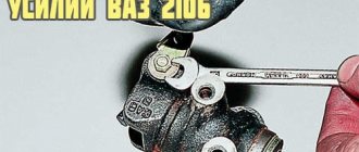
- 6. With a special 24 mm key. loosen the steering wheel nut;
- 7. Then, grasping the steering wheel with our hands, with sharp movements, swaying in different directions, we pull the steering wheel toward ourselves;
- 8. Having torn the steering wheel from its place, unscrew the nut 24 to the end and remove it;
- 9. Under no circumstances should you press hard on the moving part of the slip ring.
AutoFlit.ru
Maintenance and testing of the VAZ generator
Generator Maintenance
- in cleaning external surfaces.
- in checking the fastenings of the generator to the engine.
- in checking the reliability of wire connections with the generator and voltage regulator
- in checking the tension of the generator drive belt (if the tension is weak, the generator will operate unstably; if it is strong, the belt and bearings will wear out quickly). The check should be carried out every 10 thousand km. mileage
- in checking the condition of the generator belt (there should be no cracks or delaminations on it).
- in checking the condition of the generator bearings (remove the belt and rotate the generator rotor by hand; if jamming, play, noise or clicks are observed, the bearings should be replaced).
Replacing the brake light, tail light, turn signal lamp on a Priora
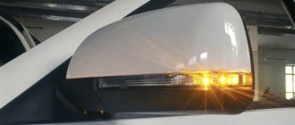
To remove one of the lamps, you need to grab its “socket” with your hand and turn it slightly counterclockwise. After which the lamp is removed from the base of the lantern.
Now, in the same way, we take the lamp itself, and turning it counterclockwise relative to the socket, we remove it.
Replacing the lamp is carried out in the reverse order. It is worth keeping in mind that when installing new bulbs in the Priora's taillight, you must adhere to the same rules as with the front headlights. That is, you should not touch the glass of the lamp with bare or dirty hands, otherwise this will lead to a decrease in its service life.
After all the necessary work has been completed, you can begin installing the flashlight in its place by tightening all the retaining screws and closing the special technological pocket with Velcro. The price of each such lamp is no more than 50 rubles, and if you replace the lamp, you will have to fork out for it, since you can buy it no cheaper than 1400 rubles for a standard factory-made DAAZ.
Photo report on removing the steering wheel yourself
First of all, read the material on removing the driver's airbag on a Priora. Then, when you have dealt with this, you can proceed further. Disconnect the power wires to the sound signal.
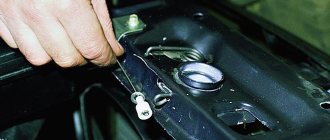
Then we put the head on 24 and rip off the nut, but don’t unscrew it completely yet. Before you start knocking it off the shaft, you need to mark the position of the steering wheel relative to the shaft - you can make marks on the steering wheel and casing.
When the nut is loosened, leave it on the shaft for now. Then we take and knock down the steering wheel from the reverse side, tapping it with medium force - on both sides.
When it comes off the splines, you can finally unscrew the nut and remove it from the shaft.
Carefully thread the horn power wires, as well as the airbag power wires, through a special hole.
And now the steering wheel is finally freed and you can remove it completely from the Priora.
If there is a need for replacement, then we perform it in the reverse order. Of course, the installation is carried out according to the marks that were originally set. The fastening nut must be tightened with a torque of 31 to 41 Nm. But you can take the average value and tighten it with a force of 40 Nm.
Common causes of malfunctions
All that remains is to talk about why such situations arise and what the motorist himself needs to do in order to restore the functionality of the horn.
Since a car signal consists of a fairly large number of components, the reasons must be looked for in them. To do this, it is good to understand the device, design and principle of operation of the warning system.
- Blown fuse. A trivial but common problem. The fuse is located in a special block. Look for information in the instruction manual. Sometimes simply replacing the fuse is enough;
- Burnt out relay. Since the horn is powered through a fuse and a relay, the latter is also necessarily checked in the mounting block, and changed if the problem is with it;
- Broken horn. If everything is fine with the relay and fuse, the problem may be in the device itself. To check, you can take the element and directly supply power through the battery. When the horn is working, the signal appears;
- Short circuit. The place to start your search is with the safety socket. And then move along the chain;
- The contact ring on the steering wheel is worn out. It will need to be replaced if necessary;
- The clamping contacts on the column are worn out. A characteristic feature of domestic cars;
- The contacts have oxidized. Check the contact group for rust or signs of oxidation;
- The winding on the horn has burned out. The problem is solved by replacement;
- Violation of electrical contact;
- The cable on the steering wheel where there is an airbag is broken.
Removing and installing a rear light on a Priora
So, first of all, we open the trunk lid, and on the inside we find a special technological window with Velcro that needs to be opened. It is through this that you can get to the flashlight mounts.
It is worth noting that from the inside it is not mounted with bolts, but with special plastic screws that secure the lamp to the car body. There are three of them in total, of course, each of them must be unscrewed. After this, we move the lantern to the side from the outside, as is clearly shown in the photo below.
If it is necessary to replace the rear light, then each of the lamps should be pulled out of the light housing from its rear part. More on this below.
Procedure when the window regulator does not work
The design of the Priora's window regulators differs from the usual ones, which use a relay and a window regulator fuse. AVTOVAZ made the glass control using an electrical package control controller (TSBKE), which is located near the ECU.
1. Check the TsBKE fuse in the mounting block (F31, 30A).
2. Remove the door trim and check the voltage at the power window motor terminals using a multimeter or a 12V test lamp.
If there is no voltage, then check the serviceability:
- window control unit (buttons in doors)
- wiring (connector connection)
- electrical package control unit, which is located above the ECU unit (more on this below)
If current flows to the electric motor, but the glass does not move, then we check:
- malfunction of the window lift motor (for example, the drive motor brushes are stuck/sticking, the plastic gear in the gearbox is worn out)
- The window lift cable is frayed
- glass is jammed (distorted)
The most common problems with power windows are:
- Faulty double-glazed window control unit (GCU)
- Window lift motor malfunction
- Skewed, broken power window cable
- Poor contact
What functions does the block provide?
The main functional purpose of the device is to monitor and control the electrical system in the car. Some important functions for which the block is responsible:
- fog lights, low beam, side lights;
- lighting in the car interior;
- direction indicators;
- power window system;
- operation, adjustment and heating of side mirrors;
- anti-theft system;
- signaling;
- door locking;
- trunk lighting;
- instrument panel lighting.
Partial, and even more so complete failure of the unit causes significant trouble for any car owner. The biggest problems are caused by the failure of the comfort unit in dense city traffic conditions.
Types and causes of malfunctions
Statistics show that 70 percent of Lada Kalina car owners, to one degree or another, encounter problems associated with incorrect operation or complete failure of the horn. The fact is that the horn itself is installed between the radiator and the car body, so it is exposed to increased negative effects of an aggressive environment (dampness, high temperature, cold, icing). The main, main reason for the failure of the unit is the oxidation of contacts and conductive elements.
The most common reasons affecting performance:
- failure of the viburnum horn relay;
- rust of the internal elements of the speaker, which appears as a result of condensation;
- lack of contact on the movable ring of the power button;
- faulty viburnum horn fuse.
Diagnosis of the causes of the malfunction
If your sound signal does not work on Kalina, it is best to start checking its functionality with the fuse and relay, which are located in the mounting block. After the functionality has been checked, it is necessary to inspect and test the contacts of the horn itself using a multimeter. Quite often, the device for sending sound signals has various oxidations and contaminations, and before replacing it with a new product, it makes sense to disassemble and thoroughly clean all the component parts of the unit, especially in the places where the contact wires are connected.
Replacing the Priora comfort unit
Before purchasing a new product, you must be sure that the cause of the malfunction lies precisely in it. To do this, you can install a known-good unit in your car and test the operation of problematic units. If, with a new, serviceable device, electrical consumers operate normally, the old comfort unit is faulty. Otherwise, use an integrated approach, check fuses, relays, wiring, and all kinds of drives. In other words, the entire technical chain with which the faulty unit usually comes into contact during operation.
Replacement of the device is carried out in 7 simple steps:
- We put the car on the parking brake.
- Open the hood, loosen the negative terminal and remove it from the battery.
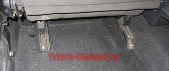
- We move into the car interior. For ease of operation, we roll the front seats back into the cabin as far as possible.
- We prepare the tool. Using a screwdriver, unscrew the mounting bolts and remove the 2 side walls.
- Using a 10mm wrench, unscrew the two fastening nuts.
- Carefully remove the block itself. When removing, rotate the product so that it does not hit other elements. Disconnect two contact connectors, the first is power, the second is information.
- Remove the faulty product and install a new one.
In the future, in order to inspect, diagnose or repair the Priora comfort unit, you will need to remove its protective housing. When purchasing a new unit, keep your sales or sales receipt. If you purchase a faulty device, this will allow you to return or exchange it for a new one. Prices for the product vary depending on the specific seller and range from 2,500 rubles to 10,000 rubles.
Lada Priora Hatchback “Priorka” › Logbook › Long ago and banal: signals from the Volga.
. In the second month after buying the car. Ideally, each signal should be attached to a strip of springy steel, then it will be even louder. But there is not much space in front of the radiator. Initially, I didn’t want to place signals, as many do, on the right and left behind the bumper, on the right and left of the side members. It is not right. Sound waves should have no obstacles in their path.
I installed Volgov ones. I had to slightly file the plastic of the horns on the side of the A/C radiator, otherwise they were very close. All power wires are 4mm2 (four squares) and of minimum length, laid in corrugations. Soldering everywhere, no crimping. A wire with a closed adapter for a 20A blade fuse comes from the positive terminal of the battery. I used closed terminals (in housings) and filled them with graphite (or Litol, I don’t remember) to reduce oxidation.
I also coated the signal studs and nuts generously with graphite.
Additional relay on the washer reservoir mounting stud. Directly from the stud, I took the ground through the terminal for the relay winding (pin 85). The 86th contact of the relay was connected with a wire to the standard signal connector.
Closed adapter for a 20A blade fuse near the positive terminal of the battery (hid behind the battery):
So these signals worked for almost 7 years. In the winter of 2017-2018, one tone began to fail, and then stopped working altogether. And a year ago I replaced them with a new set.
6 years ago signals from the Volga were installed. Original (Lyskovo). I took them off my broken 9 before selling it (probably a bad omen in vain. The Priora was beaten many times later...). So these signals are from 2010.
At the end of last year they started to glitch. And the signal volume was no longer the same. At the beginning of January of this year, one signal simply failed (high tone) and subsequently worked spontaneously.
Sports steering wheel (Pros and Cons)
Conclusion
over your safety. The worst option is if you buy a steering wheel that is made of hard material and is not capable of deformation.
above the price. a branded steering wheel is usually manufactured at the factory, under the careful supervision of specialists
This kind of enterprise sometimes specializes exclusively in “steering wheels”, so attention, effort, knowledge and resources are aimed only at making a steering wheel, which, once picked up, cannot be let go. The price of a high-quality steering wheel cannot be lower than a standard factory one.
undergoing technical inspection
You will not pass MOT if you have an alternative steering wheel installed and do not have a certificate confirming that this steering wheel complies with GOST.
xn—2111-43da1a8c.xn—p1ai
Troubleshooting methods
If the check reveals a short circuit, it is easier to immediately replace the part with a new one. To restore normal conductivity on the “nickels” and correct a break in the holding winding at the fastening point, disassemble the spare part, desolder the terminals, clean the copper from oxide, reassemble, and tighten the fasteners.
Depending on the manufacturer and year of manufacture, the solenoid relay comes with a detachable housing (the cover of the power contacts is secured with screws) and with a one-piece housing (rolled into the metal of the housing). Diagnostics of both types of parts can be carried out without opening them, but there is a problem with repairs: with “one-piece” parts, the body is very difficult to assemble neatly and can easily be damaged during assembly. A cracked cover is unsuitable for further use. If you have little experience in fine work with electromechanical devices, it is easier to purchase a new, known working relay.
Do-it-yourself removal and disassembly of a VAZ generator
Replacing the VAZ 2110 generator
- Disconnect the generator excitation wire.
- Unscrew the nut securing the wires to terminal “B+” using a “10” wrench.
- Remove the “B+” terminal wires.
- Remove the generator tension bar.
- Unscrew the nut of the lower mounting of the generator using a “13” wrench.
- Remove the mounting bolt.
- Remove the tens generator.
Removing the generator voltage regulator
- Release the 3 spring clips and remove the protective cover of the generator diode bridge.
- Unscrew the 2 screws securing the voltage regulator using a Phillips screwdriver.
- Disconnect the block with the wire from the output of the relay-regulator and remove it.
Removing the diode bridge from the generator
- Unscrew 3 bolts that connect the terminals of the stator windings to the rectifier block (1) using an 8-mm spanner, and 1 more bolt holding the diode bridge (2). Remember how the isolating and thrust washers are installed.
- Bend the wires of the stator winding leads to the side.
- Unscrew the capacitor mounting screw using a Phillips screwdriver.
- Remove the diode bridge along with the capacitor. Unscrew the 2 contact bolt nuts using a 10mm socket wrench. Remove the spacer and insulating bushings from the bolt, remove the bolt from the diode bridge and the capacitor tip from the contact bolt.
Replacing the front and rear bearings of the generator
- Before removing the front and rear covers of the generator, you should mark their location with a marker.
- Unscrew the 4 bolts using an 8mm socket wrench.
- Open the generator covers using a flathead screwdriver.
- Disconnect the back cover from the front along with the stator winding.
- To remove the front bearing of the generator, you need to attach a suitable object to it, for example, a “27” socket. Then knock it out with hammer blows.
- Lubricate the bearing seat.
- The front bearing is installed using the old one. Place it on top and carefully drive the bearing in a circle.
- The front generator bearing is installed.
- If a special puller is not available, then a large open-end wrench will be required. We pick up the rear bearing with a wrench, as shown in the photo.
- Lightly hit the key with a hammer and move it around in a circle to remove the rear bearing of the generator.
- The rear bearing has been removed from the generator rotor shaft.
- Installation of the rear bearing can be done using a piece of pipe of a suitable diameter (for example, a deep “19” socket). Using light blows of a hammer, press the new bearing onto the generator rotor shaft.
xn--2111-43da1a8c.xn--p1ai
Video review on removing and installing the steering wheel on a Priora
The video repair report shown below is embedded from my author's YouTube channel, so you can watch this video either on this site or follow the link to the channel.
Symptoms: The steering wheel is bent.
Cause: The steering wheel is faulty.
Tools: flat screwdriver, socket set, wrench set, Phillips screwdriver.
1. Remove the negative cable terminal from the corresponding battery terminal.
2. Set the steering wheel to the position corresponding to the straight-line movement of the car.
3. Unscrew and remove the two airbag mounting screws.
4. Rotate the airbag.
5. Pry off the green retaining element of the control wire block using a screwdriver.
6. Move the fixing element to the side.
7. Disconnect the wire connector and then remove the airbag.
8. Press out the retaining element of the wiring harness block.
9. Disconnect the wired horn connector.
10. Mark the relative position of the steering shaft and steering wheel using colored markers.
11. Lightly unscrew the nuts securing the steering wheel to the shaft.
12. Rip the steering wheel off the steering shaft using sharp blows with your hands.
13. Completely unscrew the steering wheel mounting nut.
14. Remove the steering wheel.
Installation of the steering wheel is carried out in the reverse order of dismantling, observing the marks on the steering wheel and on the shaft.
Sources
- https://almazcar.ru/priora/lada_priora_diametr_rulya.html
- https://priora-remont.ru/kak-snyat-rul-s-podushkoj-bezopasnosti/
- https://www.avtika.ru/qa/771-snjatie-zamena-ustanovka-rulja-lada-priora
Alternative options
In this case, the possibilities are limited solely by the imagination of the Vesta owner. Most often, sound signals from the Volga are installed on the Lada, since their sound is much louder. But there are other ways. The most common options for such “modernization” are:
- installation of signals from the Volga - in this case, different installation methods are possible (with connecting a relay in the cabin or under the hood)
— installation of other signals;
— installation of a signal with an integrated compressor;
— a combination of signal and high beam.
Installation of signals from Volga
It involves not only installing “shells” directly on Vesta, but also various options for connecting them. It is worth remembering that the sound signal from the Volga can be either old or new. However, they have no differences, except for a slight difference in tonality:
— sound signals Volga-3110 (22.3721/221.3721) – low and high tone;
- sound signals Volga, RAF S302/303D - low and high tone.
Sound pressure – 105-118 dB.
It is necessary to take into account that simply replacing the signals on Vesta will not work, because their current consumption is different. For Vesta this figure is 5A (passport data), although in reality it usually does not exceed 3.5A. Signals from the Volga consume 8A each, which gives a total of 16A. Therefore, for their installation it is necessary to use a 4-pin type relay. In particular, you can use relay 904.3747-10.
In addition, on Vesta, only one plug is supplied to the factory signal - “Plus” is permanent, since it supplies power to the fan, and “Minus” comes from the button on the steering wheel. Regarding the Volga signals, they only need “Plus”, because “Minus” goes directly through the metal mount to the body.
It is also necessary to take into account the dimensions of the sound signals - the Volgov ones are larger than the standard ones on Vesta. Therefore, installation in factory locations is excluded. In addition, it is not advisable to mount them directly to the body, as this will lead to vibration, and the sound of resonating metal will be mixed with the horn. So the best solution would be to use a bracket. The advantage of this option is its low cost - a set of “Volgov” signals will cost about 1,000 rubles.
Installation of relays in the interior of Lada Vesta
This is done directly in the fuse box. To carry out the work you will need the following components:
— sound signals from the Volga;
— 4-pin type relay;
— terminals – wide (6 units) and narrow (1 unit).
For installation, it is best to use the free space in the fuse box, to which the wires from the contact relay, which is responsible for activating the signal on the steering wheel, are transferred. In the place that has become vacant, a wire from relay contact “87” is placed. Next, you will need to remove the wire from the 13th contact block and insert it into the 13th connector “87” of the relay contact.
To supply “Plus”, you will need to feed the wire to relay contact “30” from connector “Ш5-6”, using a jumper of contact “86”. In this case, you will have to insulate the wire in red-white or black-white color, since “Plus” always goes to it.
This method has a number of advantages:
— location of wiring under the hood;
— installation of the relay in the appropriate block, which guarantees dryness;
— use of a separate “Plus”.
However, if you have a complete lack of experience and knowledge in the field of car electrics, it is better to contact an auto electrician when installing a relay in the cabin.
Installation of a relay under the hood of Lada Vesta
Regarding the components, they are similar, but the list will need to be supplemented with a few more elements:
— pendant type fuse;
- plastic corrugation - 2 meters.
The installation of the beeps themselves is carried out in a convenient place, and the connection is made according to one of two schemes:
- Using “Plus” directly from the fuse block;
- Using “Plus” directly from the battery, using a separate fuse.
In general, the second option is preferable. The relay should be located in a place protected from moisture. In addition, it is recommended to first wrap this component in polyethylene or insulate it.
The work is quite simple - you will need to dismantle the Vesta bumper and remove the factory signal, and then you can begin assembly. First, it is necessary to properly insulate the wires, and it is recommended to pass the wire that connects the signals through the corrugation so that it does not fray over time. Then you will need to fix the relay, after which you can put everything back together.
Combined option
This method involves retaining the standard Vesta beeps, but installing “Volgov” ones as additional ones. At the same time, combining 2 different tonalities will be a very original and specific move. Fixation is carried out in the same way as in previous cases, in any convenient place through a bracket. After which you will need to properly insulate all connections so that dirt and moisture do not get on them.
Installation of other sound signals on Lada Vesta
It is not necessary to concentrate exclusively on “Volgov” signals, since you can use beeps from other manufacturers. There are a lot of options on the market from different brands that you can buy - MITSUBA HOS-04GL, Elephant CA-10100 12v, GMP France / 410-510Hz and others.
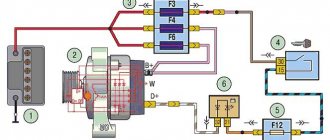
Relay and fuse blocks
The VAZ-2170 has three relay and fuse blocks:
- main block;
- mounting block;
- additional mounting block.
Luxury "Priors" with air conditioning have another additional block in which relays and fuses are located that are responsible for the operation of climate control equipment.
Main power fuse block
The main unit is located in the engine compartment of the car next to the battery and expansion tank. It is protected from above by a removable plastic casing. The main unit contains only six fuses that are responsible for the operation of the main (power) electrical circuits of the car.
To replace the fuses in the main unit, you need to disconnect the ground on the battery, remove the cover and replace the faulty part. VAZ-2170 mounting block
Relays and fuses in the cabin
The mounting block is located in the car interior under the dashboard on its left side. It is protected by a removable plastic panel attached to the “torpedo” using three latches. To remove the panel you need to turn each of these latches 900 degrees. After this, the panel will be completely removed.
The location, number, and markings of relays and fuses in the Priora mounting blocks may differ depending on the type of vehicle equipment.
Mounting block fuses
To remove the mounting block from its seat, you only need a screwdriver with a Phillips bit. She needs to unscrew the screw securing the block, then, pulling it towards you, disengage it from the fastening hooks.
Before replacing relays and fuses, you must disconnect the negative terminal from the battery. To remove the main unit, you will need to disconnect all terminals with wires connected to it, having previously marked their location.
Additional mounting block
The additional VAZ-2170 mounting block is located behind the panel of the right tunnel trim on the left leg side of the front passenger. To get to it, you need to unscrew the screws securing the cladding and remove it.
The additional mounting block contains three fuses and two relays.
To replace fuses and relays in the additional unit, there is no need to remove it from its mounting location. To remove the relay, you should unscrew the corresponding nut securing it with an “8” wrench. Before carrying out work to replace the relay, fuses or the entire unit, it is strongly recommended to disconnect the ground wire from the battery, and also disconnect the wiring harness block of the electronic engine controller from the additional connector mounting block.
Control and protection unit for climate control devices
In “Priors” equipped with climate control equipment, another additional mounting block is installed. It is located next to the main unit, and is attached to the “glass” of the left rack. Depending on the manufacturer of the climate system, the relays and fuses in it may have different locations and purposes.
Recommendations
Comments 50
You can install one set without a relay and not worry, but if you install 2 sets or more, then you cannot do without a more powerful (than standard) relay. I have 2 sets of Volgov horns, for them I took a separate + from the battery and through a relay.
I’ve been driving with Volgov signals for seven years, everything works fine, I connected it without any modifications, I took the car from new, I didn’t even bother whether there was a relay there or not, I signal often.
I installed Volga signals on the Priora, without a relay, without replacing the standard fuse. This is not the first car I have changed the signal. Nothing ever burned down anywhere. I use the signal, but I didn’t go to a wedding while driving.
don't get carried away! I installed it without a relay and I’m happy, everything is fine. and I like to honk at all sorts of woodpeckers)
I’ve been driving with Volga signals for 4 years without additional relays and everything is fine! At a friend’s wedding, he honked a lot because the rest of the cars had factory beeps)))))
install a relay and that’s it... the chip itself will be a control plus for you, they’ve already given you the circuit... do it right.
I don’t know what’s wrong with the signal and what’s connected with it, I just want to screw your brains with what you wrote. The fuse that you wanted to change to a larger one is needed not by the signal, but by the wiring, like any other, that is, if you increase it and load the wire, it will melt and then light up, and the oversized fuse will not even light up unless it is shorted to ground... this It’s a mistake of many people and you have to remember that fuses, circuit breakers at home, are installed for adjustment, not for devices... regarding the relay, just take it out and it says on it how many amperes can be loaded on it, it’s simple. and by the cross-section of the wire you can determine the maximum current for it and you will understand what is the maximum for wiring in this case, you can install a fuse, download the sign on the Internet for yourself))
Thank you) Yes, I already realized that I was stupid)) I’ll install an additional relay)
I don’t know what’s wrong with the signal and what’s connected with it, I just want to screw your brains with what you wrote. The fuse that you wanted to change to a larger one is needed not by the signal, but by the wiring, like any other, that is, if you increase it and load the wire, it will melt and then light up, and the oversized fuse will not even light up unless it is shorted to ground... this It’s a mistake of many people and you have to remember that fuses, circuit breakers at home, are installed for adjustment, not for devices... regarding the relay, just take it out and it says on it how many amperes can be loaded on it, it’s simple. and by the cross-section of the wire you can determine the maximum current for it and you will understand what is the maximum for wiring in this case, you can install a fuse, download the sign on the Internet for yourself))
... well, I’ve been driving with Volgov for 8 years without special extras and everything is fine. and apparently I’m not alone. in my opinion, these are the pens of “experts”
And no one is forcing anyone to install a relay, people are just trying to point out the truth :) Do you know how reliability is calculated for products for the defense industry? (I think you can hardly imagine) For example: all power circuits (over 10A) are duplicated by a second wire = ) one of the examples of reliability... It’s bad that we have such a mentality... Everything is “Russian at random” And the chimney with the hood is at random... And these are not “the pens of experts”, you can’t fool physics... there are a lot of people like this: “My life my rules”...
I think comparing the requirements for defense equipment and the beeps on the Priora... this is kind of extreme. It’s not just maybe, but it works. long and hard. When I installed the amplifier on speakers and a sub, I calculated the cross-section of the wire and the fuse. when I made the box for the subwoofer, everything was also taken into account and done “measure seven times - cut once.” Rationality is needed in everything IMHO. and putting duplicate wires on everything... it's overkill.
Well, no one talks about redundancy) here they say it correctly... You can’t fool physics. Note that I wasn’t the only one who said about the need for installation... it means there’s something in it
everyone decides for themselves what and how to do. I have my own experience. I’m writing about him. The theory is difficult - I’m not a physicist (but an economist)
I didn’t install anything, no additional relay, no additional fuse, everything is standard. Everything works, everything beeps. Details in the blog.
I don’t know about Prior, but in 10 families, when connecting Volga signals without pressing the signal button, they immediately start yelling, since the control wire is the mass of the car. And Volga signals, on the contrary, + is the manager. So in our case we install an additional relay. And this way we simply correct the situation. The first time I plugged in the Volga signals myself and they started yelling. I had to install a relay. Well, I think it was possible to change places in the steering wheel itself. Noya did not do this.
I didn’t bother with the relays and the signals in general, I just installed the Volgo signal and that’s it, it never burned out. My only mistake was that I installed the signals on the lower grille of the bumper (water, snow, etc. clog the signals)
I took the plus with the battery; for this you need an additional relay. And I hung an additional relay on the standard wiring.
Install it and don’t worry, I understand if you’re throwing weddings then you need a relay, otherwise a one-time pipe won’t do anything, my opinion
For a year now everything has been working smoothly through the original relays and fuses.
If something short-circuits in the signals, the wiring will float!
Fuses protect against this.
The standard wire will start to melt faster than the 15-20A fuse you installed.
Who installed this fuse? The regular one is worth it!
Is the standard one enough for a 14A load? With a short press it is possible. If it lasts for a long time it will fly out
Enough. Time it? )
What I’m saying is that if you compare the operating parameters of Volga signals with the cross-section of the original wire and protection, it becomes clear that the original wire and protection are not designed for this load. Working to the limit
I'll check it out anyway. I'm already interested.
What I’m saying is that if you compare the operating parameters of Volga signals with the cross-section of the original wire and protection, it becomes clear that the original wire and protection are not designed for this load. Working to the limit
How to choose
Having decided to replace a relay or fuse in a Priora, take full responsibility for their selection and purchase. Under no circumstances should you buy cheap parts of unknown quality and origin.
It is better to give preference to original products produced by VAZ. As a last resort, buy relays or fuses from one of the well-known companies, such as Bosh, Hella or Tesla.
Replacing the sound signal on a Lada Vesta is a simple procedure that any owner should be able to perform. After all, driving without a properly working horn is a priori unsafe, and taking a car to a service station due to such a breakdown is an unreasonably large amount of time. However, replacement in the event of a malfunction is not the only need. Many people are simply not satisfied with the volume or tone of the sound signal, and they replace the standard Vesta components with alternative ones. Therefore, both of these paths need to be considered in more detail.
How to connect the Volga signal
Standard sound signals of LADA cars consume no more than 5A, and Volga horns consume 7A each. In this regard, to connect them it is necessary to use a 4-pin relay. The Volga signal connection diagram is universal for all cars:
Before starting work, it is recommended to disconnect the negative terminal from the battery. All wires are laid in corrugation. We place the relay in a place protected from moisture and dirt. The whole process is also shown in the video:
About the guarantee. If you independently modify the car in terms of electrical components, there is a possibility of refusing warranty service for the car. Therefore, the installation of signals from Volga should be carried out at a service center, where after connection they will be ready to provide a document confirming the quality of work. You can also contact an authorized dealer for such modifications.
Are you satisfied with the operation of the standard sound signal on the LADA model? Are you ready to install a Volga horn? Let us remind you that we previously looked at other methods that can make operating a car more comfortable. For example, installing a gas tank cap bracket or how to make a flip-flop ignition key.
How to check the generator on a car without removing it? Our review
- When the engine is running, the light that monitors the battery charge is either constantly on or blinking.
- The battery spontaneously discharges or boils away;
- The headlights shine dimmer than they should;
- The operation of the motor is accompanied by rattling or a low, continuous squeak. Alternatively, the generator may howl;
- As the engine speed increases, the brightness of the headlights increases sharply. This phenomenon is considered normal when revving at idle speed. However, once the headlights reach normal brightness, the intensity should no longer change. If you accelerate - they burn brighter, release the pedal - they dim, which means the generator is clearly unhealthy.
- The generator drive belt is inspected. The degree of tension is controlled; If delaminations, tears or cracks are detected, the belt is immediately replaced. In some situations, more complex actions are not required;
- The fuse is checked - like any other, it quite often fails;
- Next, you need to make sure that the rotor rotates freely, the wires are not pinched or frayed anywhere, the contacts have not come loose, and the housing is not cracked;
- The charging relay is replaced with a new one - this is the easiest way to make sure that everything is in order with it. In most cases, a visual inspection cannot give complete confidence in its performance.
- The engine starts. The meter remains connected to the battery;
- All the electrics on board start to work randomly: the heater turns on, the headlights turn on/off, more gas is periodically given, you can turn on the audio system;
- During the described executions, testimony is taken. If the voltage remains stable between 14 and 14.2 V, your difficulties are not caused by the generator. If jumps of no less than 0.5 V are noticed (and usually they reach 1 V), you have a direct path to a specialist who will find what has gone wrong in this node;
- Bearings can fail (it is they that cause the whine and whistling of the generator); the reason for the non-working condition can be clogged or worn out generator brushes, worn or again clogged rings.
AutoFlit.ru
Replacing the standard sound signal in case of breakdown
First you need to prepare the car for work by putting the parking brake on and turning off the ignition. Then you need to lift the hood and, armed with a “10” key, disconnect the negative terminal from the battery. Then you should dismantle the front bumper, which is best done with an assistant, so as not to damage the paintwork on the bumper itself and on the wings of Vesta.
Once this is completed, all that remains is to disconnect the plug with the wires from the signal horn. Then you can dismantle the signal itself, the bracket of which is attached to the body with one nut. For dismantling you will need an extension, a wrench and a 13mm socket.
Assembly is carried out in the reverse order - you need to secure the signal, inspect its operation, install the bumper with an assistant and tighten the terminal on the Vesta battery.
Installing LED tail lights on Priora
As for LED tail lights for Lada Priora cars, their prices are of course a little higher. Namely, a set of such lighting equipment can be purchased for around 3,200 rubles. As for installing a flashlight instead of a standard one, there is absolutely nothing unusual here.
It is necessary to disconnect the power connector for the flashlight, which is standard for all types of Priora, and then, after removing the old flashlight, install a new one with LED lights in its place. There is no need to perform any additional actions or manipulations. And the result of the work done can be seen in the photo below:
The Priora has three brake lights: two in the rear lights and an additional one installed in the spoiler. Their purpose is to warn drivers of cars moving behind about braking. Operating a vehicle with non-functioning brake lights is prohibited. If the lights on the Priora do not light up, you need to contact an auto electrician or fix the problem yourself. In the latter case, the driver needs to have a minimum set of tools to find and eliminate the causes of the malfunction.
Lada Priora Hatchback “Priorka” › Logbook › Long ago and banal: signals from the Volga.
. In the second month after buying the car. Ideally, each signal should be attached to a strip of springy steel, then it will be even louder. But there is not much space in front of the radiator. Initially, I didn’t want to place signals, as many do, on the right and left behind the bumper, on the right and left of the side members. It is not right. Sound waves should have no obstacles in their path.
I installed Volgov ones. I had to slightly file the plastic of the horns on the side of the A/C radiator, otherwise they were very close. All power wires are 4mm2 (four squares) and of minimum length, laid in corrugations. Soldering everywhere, no crimping. A wire with a closed adapter for a 20A blade fuse comes from the positive terminal of the battery. I used closed terminals (in housings) and filled them with graphite (or Litol, I don’t remember) to reduce oxidation.
I also coated the signal studs and nuts generously with graphite.
Additional relay on the washer reservoir mounting stud. Directly from the stud, I took the ground through the terminal for the relay winding (pin 85). The 86th contact of the relay was connected with a wire to the standard signal connector.
Closed adapter for a 20A blade fuse near the positive terminal of the battery (hid behind the battery):
So these signals worked for almost 7 years. In the winter of 2017-2018, one tone began to fail, and then stopped working altogether. And a year ago I replaced them with a new set.
6 years ago signals from the Volga were installed. Original (Lyskovo). I took them off my broken 9 before selling it (probably a bad omen in vain. The Priora was beaten many times later...). So these signals are from 2010.
At the end of last year they started to glitch. And the signal volume was no longer the same. At the beginning of January of this year, one signal simply failed (high tone) and subsequently worked spontaneously.