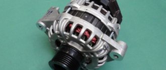
Generator connection diagram for Lada Priora VAZ-2170, 2171 and 2172
Lada Priora VAZ-2170, 2171 and 2172 are equipped with a generator 5102.3771 with the following characteristics:
- Maximum output current at 14 V = 80A
- Adjustable voltage, Volts = 13.8–14.4
- Power density = 205 W
- Generator weight = 5.4 kg.
The figure above shows a wiring diagram for the generator on the Priora , here is its explanation:
1 – battery;
3 – main fuse block;
6 – battery fault warning light
The voltage to excite the generator when the ignition is turned on is supplied to the “D+” terminal of the regulator through the battery warning lamp No. 6 in the instrument cluster. After starting the engine, the excitation winding is powered by three additional diodes installed on the generator rectifier block. The “W” output of the generator is not used on Lada Priora cars. The operation of the generator is monitored using the battery warning light located in the instrument cluster. When the ignition is turned on, the lamp should be on, and after the engine starts, it should go out. If the lamp does not go out after starting the engine, you need to take a multimeter in your hands and check the presence of voltage supply to the on-board network from the generator.
Source
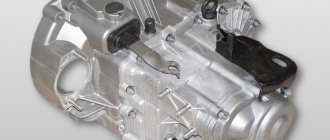
Generator device
A generator is an electrical machine that converts mechanical energy into electrical energy.
The main elements of the generator are the stator and the armature. The figure below shows the Priora generator disassembled and all its parts are described.
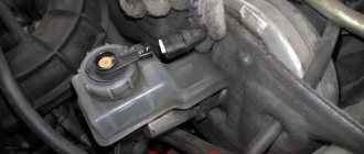
Initially, the generator produces alternating current, after which the alternating current, passing through the diode bridge, is rectified and becomes constant.
Scheme VAZ-2170 - VAZ-21728 Lada Priora
Complete information is provided about electrical equipment, wiring, relays and fuses of VAZ-2170 - VAZ-21728 vehicles. The collection is intended for auto electricians and those who, having some knowledge of circuit design, can carry out minor auto repairs with their own hands. The Lada Priora sedan (VAZ-2170) has been produced since 2007, the VAZ-2172 hatchback since 2008, and the VAZ-2171 station wagon has been produced since 2009. In 2013, the car was modernized and they began installing an AMT robotic gearbox (21723, 21728).
There are 4 main harnesses in the Priora electrical circuit:
- from the instrument panel;
- providing motor control;
- front electrical harness;
- rear electrical harness.
All these harnesses are connected to each other using detachable connections. The connectors are located under the dashboard. Each of the harnesses is assigned a serial number.
In addition to the main ones, there are also secondary ones:
- installed in the front passenger door;
- identical in both the left and right rear doors;
- installed in the driver's door;
- connecting the backlight of the license plate;
- connecting the electrical package.
Each element in the diagram corresponds to a number with an explanation. Since all elements are standardized, their designations are identical on car diagrams of all car manufacturers. Next to each electrical appliance, the connectors that go to them are indicated. The pins or sockets of the pads are also numbered.
Basic generator malfunctions
The following parts are most often susceptible to breakdown in a generator:
- Electric current collector brushes;
- Breakdown of the diode bridge;
- Break or short circuit of the stator winding;
- Bearing failure;
- Excessive wear of collector rings;
- Damage to the voltage regulator;
- Generator pulley wear;
- Capacitor breakdown;
In case of all the above-described breakdowns, it is necessary to repair the generator.
Lada Priora wiring block diagrams
1,2,3,4 – blocks of the instrument panel wiring harness to the blocks of the rear wiring harness; 5 — block of the instrument panel wiring harness to the block of the ignition system wiring harness; 6,7,8 — blocks of the instrument panel wiring harness to the blocks of the front wiring harness; 9 – lighting control module; 10 – ignition switch; 11 – on-board computer mode switch; 12 – windshield wiper switch; 13 – passenger airbag module; 14 – light signaling switch; 15 – instrument cluster; 16 – hours; 17 – diagnostic block; 18 – recirculation switch; 19 – control unit for windshield wiper and external lighting; 20 – micromotor gearbox for driving the heater control damper; 21 – rear window heating switch; 22 – alarm switch; 23 – brake signal switch; 24 – electric amplifier control unit; 25,26 — blocks of the instrument panel wiring harness to the radio; 27 – mounting block: K1 – relay for turning on low beam headlights and side lights; K2 – relay for turning on the heated rear window; K3 - starter activation relay; K4 – additional relay; K6 – relay for turning on high speed windshield wiper (automatic mode); K7 – headlight high beam relay; K8 – sound signal relay; K9 – relay for turning on the alarm sound signal; K10 – relay for turning on fog lights; K11 – relay for turning on the electric heating of the front seats; K12 – windshield wiper activation relay (intermittent and automatic modes). 28 – lampshade lighting of the glove box; 29 – glove box lighting switch; 30 — automatic lighting control switch; 31 – electrical package controller; 32 – controller of the automatic climate control system; 33 – rotating device; 34 – driver airbag module; 35 – sound signal switch.
Alternator belt: how to tension, what tension should be and how to check
How to tension the alternator belt
Many car owners are interested in the question: how to tighten the alternator belt? After all, the battery charge level and the voltage in the car’s electrical network depend on this. Also, the condition of the belt itself, as well as the condition of the crankshaft bearings and the generator shaft, depend on how the generator belt is tensioned. Next, we will analyze in detail how to properly tension the alternator belt with a specific example.
The importance of tension level and checking it
Let's consider what unpleasant consequences an incorrect level of tension will lead to. If it is weakened, then there is a high probability of slippage. That is, the generator drive will not operate at rated speed, which in turn will lead to the level of voltage generated by it being below normal.
The result is an insufficient level of battery charging, insufficient electricity to power the vehicle systems, and operation of the electrical system under increased load.
If the belt is too tight, this can also cause excessive wear on the belt itself. And in the worst case, even to its breakage. Also, excessive tension has a detrimental effect on the bearings of the crankshaft and generator shaft, because they have to work under conditions of increased mechanical load. This leads to excessive wear and speeds up their failure.
Tension check
Tension checking process
Now let's look at the issue of checking tension. It’s worth mentioning right away that the force values are unique and depend not only on the make and model of the machine, but also on the generators and belts used. Therefore, look for the relevant information in the manuals for your car or in the operating instructions for the alternator or belt.
This will also be influenced by the presence of additional equipment installed in the car - power steering and air conditioning.
In general terms, we can say that if you press the belt on the longest section between the pulleys with a force of about 10 kg, then it should deviate by approximately 1 cm
Instrument cluster block diagram
| № | Decoding |
| 1 | Electric power steering |
| 2 | Emergency gang control VAZ-2170 |
| 3 | Connection to oil pressure sensor |
| 4 | Parking brake indicator light |
| 5 | Electronic anti-theft device |
| 6 | Airbag control module |
| 7 | External lighting switch |
| 8 | Right turn signal indicator and doubler |
| 9 | Left turn signal indicator and backup |
| 10 | Engine control unit |
| 11 | Disabling the passenger's front airbag |
| 12 | Seat belt warning light |
| 13 | ABS brake system unit |
| 14 | Steering column switch button |
| 15 | Brake expansion tank indicator |
| 16 | ABS safety control module |
| 17 | Main beam headlight control unit |
| 18 | Shield backlight module |
| 19 | General disadvantage of the device |
| 20 | Constant positive battery terminals |
| 21 | Ignition switch contact |
| 22 | Fuel flow meter |
| 23, 24 | Steering wheel turn switches |
| 25,26 | Overboard temperature sensors |
| 27 | Fuel sensor VAZ-2170 |
| 28 | Speed sensor |
| 29 | Coolant temperature sensor |
| 30 | Tachometer signal |
| 31 | Shield diagnostics |
| 32 | Generator Regulator Relay Terminal |
Electrical connection diagram for heater wiring harness PRIORA 21723
- heater wiring harness block to the front wiring harness block;
- air mixing gearmotor;
- evaporator temperature sensor;
- electric fan 2172;
- speed controller;
- recirculation gearmotor.
Parking system sensor diagram 2172-3724248
1,2,3 – parking system sensors; 4 – block of the wiring harness of the parking system sensors to the block of the rear wiring harness.
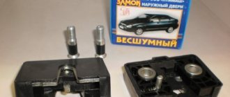
Rear license plate light pinout
1. Supply voltage to the lights illuminating the rear number 2,3. Priora 4 license plate lamps. Electric trunk lid locking motor
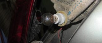
Replacing Priora generator brushes
The relay regulator is made together with brushes. At first I removed the generator to replace the relay regulator, but this task turned out to be quite labor-intensive due to the inconvenience of its location, especially the Priora with air conditioning and the hose prevents me from doing this. The second time I did not remove the generator.
Disconnected the wires. I took off the back cover, it is secured with three latches on the sides, you just push them out and the cover can be easily removed
Removing the regulator relay was also not difficult; you just need to unscrew the two mounting screws and disconnect the connector from the regulator relay contact.
Putting everything back together wasn't too difficult either. The photo shows the relay regulator after I trimmed the contacts with sandpaper and then put it in place. It turned out to be in working order, but I had already purchased a new relay regulator. For some reason, brushes often fail, especially when you encounter this problem in winter, apparently this is due to high energy consumption due to the heater and loads when starting a cold engine.
And now when the prior generator does not charge, I first check the brushes
Lighting control unit diagram
| G, 56b | To the gear motor for adjusting headlights |
| 58b | Output to backlight sources |
| 31 | Mass (ground) |
| Xz | +12 volts (from terminal 15 of the ignition switch) |
| 56 | To the relay for switching high and low headlights |
| 1,3 | From rear and front fog lights |
| 2,4 | To the rear and front fog lamp relays |
| 58 | For lamps of Lada Priora dimensions |
| 30 | +12 V from terminal No. 30 of the ignition switch |
Possible generator malfunctions
Cause - Remedy
The warning light does not light up when the ignition is turned on, control devices do not work:
Fuse F12 in the mounting block has blown - Replace the fuse
Open circuit in the instrument cluster power supply - Check the connections of the orange wire from the mounting block to the instrument cluster
Open circuit in the instrument cluster power supply: no voltage is supplied from the ignition switch to the mounting block - Check the connections of the blue wire with a black stripe from the ignition switch to the mounting block and the wire itself
Ignition switch does not work - Replace ignition switch
The warning light does not light up when the ignition is turned on and does not light up when the engine is running, the control devices are working, the battery is discharged:
Instrument cluster malfunction - Replace instrument cluster
Open circuit between the instrument cluster and the generator terminal (D+) - Check the connections of the brown wires with a white stripe from the generator to the instrument cluster
Worn or stuck brushes, oxidation of slip rings - Replace the voltage regulator, wipe the rings with a cloth soaked in gasoline
Voltage regulator damaged - Replace voltage regulator
The leads of the excitation winding are unsoldered from the slip rings - Replace the generator rotor
The warning light is bright or dim when the engine is running, the battery is discharged:
Alternator drive belt slipping - Adjust belt tension
Voltage regulator damaged - Replace voltage regulator
The diodes of the rectifier unit are damaged - Replace the rectifier unit
Additional power diodes of the field winding are damaged - Replace the rectifier unit
Open or short circuit in the stator winding - Replace the stator
The warning light comes on when the engine is running, but the battery does not charge.
Voltage regulator damaged - Replace regulator
Increased generator noise:
Damaged generator bearings - Replace the rear bearing or the front cover along with the bearing
Interturn short circuit of the stator or short circuit to ground of the stator winding (generator whine) - Replace the stator
Short circuit in one of the generator valves - Replace the rectifier unit
Source
Priora relay and fuse blocks
Location of relays and fuses in the DELRHI 15493150 mounting block
Location of relays and fuses in the mounting block 1118-3722010-00
Relay Lada Priora - purpose
How to tension a belt and check its tension
For Priora, in addition to the original ones, similar belts from foreign brands such as Contitech, Dayco, Gates, and Flennor are recommended.
- Loosen the roller nut; you will have to hold the cage with a wrench. By then rotating this key, the clip can be turned.
- Tighten the nut against the roller. Check the quality of tension only on the long section between the pulleys. If, when pressing on the belt in this place, it bends no more than 10 millimeters, the tension is appropriate.
- If your Lada has a hydraulic booster, you should tighten it a little more. If you don't pull it tight enough, it will whistle obviously, a defect that can be easily detected by ear. Then pull it a little tighter. If you hear not a whistle, but a hum, the belt, on the contrary, needs to be lowered.
On a Priora, in a regular service, changing just the belt can cost from 300 rubles (not counting consumables). If the generator is with rollers or mounted, then the price will increase significantly to one and a half thousand rubles. Do not forget the receipt for the services provided; the warranty for the work performed must be at least six months; if the belt deteriorates due to poor installation or tension, you must demand a replacement at the expense of the service.