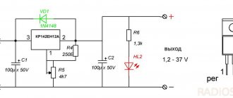
As with any car, the generator on the VAZ 2107 injector works in parallel with the battery - these are two power sources for the car, which are used in different modes. The article discusses the generator 37.3701, the principle of operation of the generator with different characteristics, including a maximum current of 80 Amperes, and provides instructions for connecting the unit. The G222 generator set is similar, you just need to pay attention to some differences.
Carburetor engines
The connection diagram for the VAZ-2107 generator (carburetor and injector) depends on the year of manufacture of the car. The first carburetor models had a G-222 generator installed. The same device can be found on commercially produced VAZ-2105 and VAZ-2104 models with a carburetor injection system.
The maximum output current for such an installation is 55 amperes. But in recent years, cars with fuel injection systems have become widespread. Its use implies a large current consumption, so it is necessary to use a generator with a high current to ensure a normal charge level and power supply to all consumers.
What to consider when choosing a new battery
According to the passport, the battery is designed for 3-5 years of active use (in reality it turns out to be less). Therefore, over time, it becomes necessary to purchase and connect a VAZ 2107 battery to replace the faulty one.
When purchasing a new battery, there are a number of parameters and characteristics to consider. Battery type: repairable and maintenance-free. The first option allows you to check and restore the electrolyte level. This allows you to use the battery longer.
The next question is what power the most efficient VAZ 2107 battery will have. This model is suitable for batteries with a capacity of 50-60 A * h. However, since modern cars are equipped with energy-intensive equipment, it is best to opt for more capacious batteries. In addition, carburetor models from VAZ require more powerful batteries - they consume more power when starting. In terms of dimensions, the VAZ 2107 requires power supplies measuring 242 * 175 * 190 mm. The vast majority of samples available on the market are suitable for them.
When choosing a battery, you should also take into account the place of residence of the owner of the “seven”. For those who live in the south, you can purchase a less powerful battery. Nordics advise giving preference to a battery with a larger capacity: in cold weather, the car starts up with greater energy consumption.
Injection engines
On injection engines, generator sets 5142.3771 or similar are used. They have increased energy, the maximum current is about 80-90 A, it all depends on the design option. Cars of the seventh series and similar models are good because they are like a designer set. You can install almost any generator on them, similar in design to the “native” one.
For tuning, installations with an output current of 100 amperes and higher are used. But the use of such devices is justified only if many powerful consumers are connected to the electrical equipment. Regardless of the design, the generators produce alternating current; a voltage regulator, capacitor and diode block are installed in the housing.
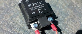
A few more words about the voltage regulator
Finally, it should be added that in cars such as the VAZ 2107, it is necessary to check the voltage supplied from the generator to the battery with a voltmeter at least once a month. We discussed how to do this above. The fact is that a car device that shows the battery charge level very often lies, showing us the norm, while the voltage at the battery terminals during engine operation is lower or higher than it. And here the danger is not so much the lack of charging as the so-called overcharging. It occurs when the voltage regulator malfunctions and is characterized by the supply of voltage to the battery, the value of which is greater than prescribed.
I personally had to face a similar problem. It all started when the relatively new battery stopped holding a charge. When using the car every day, it started without problems. But as soon as the car sat for a week, the starter made it clear with its clattering that it would not work without the “lighting” wires. A visit to an auto electrician showed that the outermost “bank” of the battery was swollen. This means that the electrodes in it are short-circuited. Why did they suddenly close if everything was in order? After starting the engine, the electrician measured the voltage at the battery terminals. The voltmeter showed 17.2 V, which is unacceptable for this battery model. At the same time, the device on the panel faithfully gave out the “norm”. Checking the voltage regulator confirmed the auto electrician's diagnosis. It was faulty. Replacing the device took no more than half an hour. And the repairs, it would seem, didn’t cost much. The battery, of course, had to be replaced, since with the onset of cold weather it began to discharge even faster.
About six months later, I accidentally noticed that the car’s headlights began to shine noticeably brighter. Then one of the headlights burned out. A week later, another one burned down. Without waiting for the battery to swell again, I decided to carry out diagnostics and repairs myself. Armed with a multimeter, I went to the garage. The measurement results again showed that the voltage regulator was faulty. This time the generator produced 15.6 V. I no longer went to the electrician. I removed the generator myself, replaced the regulator and installed everything in place. The control voltage measurement showed 14.2 V. After that incident, I regularly measure the voltage twice a week. More than a year has passed and everything is back to normal.
Unfortunately, the VAZ 2107 cannot be called a reliable car. But it still has one advantage - simplicity of design. Therefore, it is not at all necessary to contact specialists if minor malfunctions occur.
Cars before 1986
The G-222 generator was used in cars. The connection diagram for the VAZ-2107 is almost the same as on later models. But there are features, among the main ones - there is a control lamp indicating battery charging. Moreover, it worked using an electromagnetic relay.
When the ignition is turned on, power is supplied from the lock through the instrument panel fuse to the electromagnetic relay of the battery charge lamp and the coil contact. The second contact of the coil is connected to the center wire on the generator (the point where the three windings connect).
The electromagnetic relay has normally closed contacts, so when the ignition is turned on, the lamp lights up. But as soon as the engine starts running, the generator produces current. And a current flows through the control lamp coil, which causes the armature to attract and open the contacts.
At the same time, the power to the incandescent lamp stops and it goes out. This indicates that the battery is charging normally. Only when the power supply to the lamp stops will voltage be applied to the excitation winding and the generator will be able to return to operating mode.
Confronting attackers
Due to the fact that the battery is not cheap, the problem of protecting the VAZ 2107 battery from theft is quite acute. Opening the hood of a “classic” is not difficult, so thieves keep a close eye on the “seven”.
Experts offer several options for preventing theft.
- Secure parking or secure garage.
- Alarm installation.
- Installing a hood lock. Let’s be clear right away: few people take this step. Welding work is required, the appearance deteriorates and it is quite easy for a professional to pick the lock.
- Take the battery with you. The timing is inconvenient but effective. If you leave the car for a short time, it is defenseless: the battery can be removed in the parking lot near the supermarket.
- Reliable battery mount. Almost the most popular method. Fasteners are installed with a secret that prevents disassembly and makes theft difficult. Combined with reporting, this is a very effective method.
But all experts agree that the most reliable protection for the battery against theft of a VAZ 2107 is complete. A combination of multidirectional measures will give the best results!
Cars manufactured in 1996 and later (carburetor engines)
The connection diagram for the G222 generator on a VAZ-2107 after 1996 differs from the previous one in one small feature - the power supply to the excitation winding has been changed. Cars have been improved, and some improvements make it possible to kill two birds with one stone - simplify the design and make the fate of the driver easier.
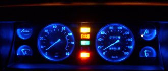
After 1996, instead of a warning lamp, they began to install a voltmeter, which more or less accurately shows the battery charge level. And if the lamp allows you to monitor only the presence or absence of voltage on the generator, then using a voltmeter the driver visually assesses the level. And if necessary, it can understand that repairs or maintenance are necessary.
Video - Battery protection from theft
In this article you will learn why the VAZ 2107 does not charge and how to solve this problem. There are many reasons for this behavior of the car’s electrical equipment, so you will have to look for the breakdown using a elimination method. It doesn’t matter whether the generator is working properly. It may work fine, but won't charge. Now let's try to find out all the possible reasons.
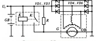
Generator circuit for injection engines
In fact, the design of the generator set is not much different from those installed on carburetor engines. Only the type of excitation and serviceability monitoring differ. The dashboard contains not only a warning lamp, but also a voltmeter; these two devices allow you to assess both the presence and level of charging. Current flows through the lamp filament and is supplied to the field winding when the engine starts. The connection diagram for the VAZ-2107 generator, regardless of the year of manufacture, implies operation in the following mode:
- When the ignition is turned on, power is supplied to the excitation winding. A magnetic field appears around the armature.
- When the crankshaft rotates with the starter, the generator armature also begins to move. With the help of movement and a magnetic field, a potential difference arises at the ends of the stator windings.
- From the windings, voltage (alternating, three-phase) is supplied to the rectifier unit, and from it to terminal “30” of the generator.
- Pin “30” is connected to the battery (positive terminal). Consequently, the entire electrical system is powered and the battery is charged.
In this case, the battery and generator G221A work in parallel. The connection diagram for the VAZ-2107 with carburetor and injection engines is almost identical, with only minor features.
Operating principle of the unit and charge indicator lamp
The operating principle of the generator 37.3701 and G222 are identical. The generator device converts the mechanical energy that appears when the crankshaft rotates into electrical energy. The resulting electricity is needed to power the on-board network and recharge the battery. Alternating current is converted into direct current with a power of 80 Amps thanks to a rectifier unit consisting of 6 diodes.
A three-level regulator maintains the voltage at the required level. After turning on the ignition, the voltage passes through the control lamp, reaches a three-level regulator, and then goes to the excitation winding.
This process can be clearly represented in the form of a diagram:
Generator wiring diagram
In the diagram, the main parts of the on-board network are marked with the following numbers:
- Battery.
- Generator set.
- Mounting block.
- Egnition lock.
- Voltmeter for measuring voltage.
- A lamp that monitors battery charging.
Power comes from three diodes, which are located in the rectifier unit. If, after turning on the ignition, the indicator light does not go out, this means that the battery is not sufficiently charged. In this case, it is necessary to check what voltage is in the on-board network. Technical characteristics of the generator: at a voltage of 13 V, the maximum current is 55/80 Amperes (video author - Vladimir Zagrivy).
If the voltage is not normal, the reason may be:
- short circuit occurring in the network;
- battery malfunction;
- breakdowns in the three-level voltage regulator;
- malfunction of the VAZ 2107 generator set with an injector.
In this case, you need to check the degree of tension of the drive belt, the condition of the bearings, and the serviceability of the three-level regulator. In addition, it is worth checking the battery charge and expiration date. Since generators 37.3701 and G222 installed on a VAZ 2107 with an injector and carburetor do not differ much, their care is the same for both models. It is enough to ensure that moisture and dirt do not get on them.
Electrical diagram VAZ-2107 carburetor
Electrical diagram of VAZ 2107, 21074 produced in 1988-2001 with generator 37.3701
- block headlights
- side direction indicators
- accumulator battery
- starter relay
- carburetor electro-pneumatic valve
- carburetor microswitch
- generator 37.3701
- gearmotors for headlight cleaners *
- Fan motor switch sensor
- engine cooling fan motor
- sound signals
- distributor
- spark plug
- starter
- coolant temperature gauge sensor
- engine compartment lamp
- low oil pressure warning sensor
- low brake fluid level indicator sensor
- windshield wiper motor
- carburetor electro-pneumatic valve control unit
- ignition coil
- headlight washer pump motor *
- windshield washer pump motor
- mounting block
- windshield wiper relay
- hazard warning and direction indicator relay
- brake light switch
- reverse light switch
- ignition relay
- ignition switch
- three lever switch
- hazard switch
- socket for portable lamp**
- heater fan switch
- additional resistor for the electric motor of the heater (stove)
- rear window heating indicator lamp
- low brake fluid level warning lamp
- signaling unit
- heater fan electric motor
- glove compartment lamp
- light switches on the front door pillars
- switches for warning lights of open front doors ***
- front door open warning lights ***
- connection block
- cigarette lighter
- watch
- instrument light switch
- diode for checking the serviceability of the low brake fluid level indicator lamp
- fuel level indicator
- fuel reserve indicator lamp
- speedometer
- turn signal indicator lamp
- carburetor choke indicator lamp
- battery charge indicator lamp
- carburetor choke warning switch
- instrument cluster
- econometrician
- light switches on the rear door pillars
- coolant temperature gauge
- tachometer
- parking brake indicator lamp ("handbrake")
- low oil pressure warning lamp
- high beam indicator lamp
- indicator lamp for turning on external lighting
- voltmeter
- parking brake indicator switch ("handbrake")
- outdoor light switch
- rear window heating switch with backlight
- rear fog light switch with on/off indicator *
- fog light circuit fuse
- lampshade ****
- tail lights
- level indicator and fuel reserve sensor
- connectors for connecting to the rear window heating element *
- license plate lights 2107
Wiring diagram VAZ-2107 carburetor - full view:
Mounting block connection diagram
P1 — relay for turning on the heated rear window; P2 - relay for turning on the headlight cleaners and washer; P3 - relay for turning on sound signals; P4 - relay for switching on the electric motor of the engine cooling system fan; P5 - headlight high beam relay; P6 - low beam headlight relay; A - the order of conditional numbering of plugs in the mounting block blocks. The outer number with the letter “Ш” in the plug designation is the block number, and the inner number is the conventional number of the plug.
Schemes of individual blocks of the seven
Power supply system
Power plant starting system
1 - starter; 2 - relay; 3 — ignition switch; 4 - battery
Ignition system
1 - generator; 2 — ignition switch; 3 - distributor; 4 - breaker; 5 — candles; 6 - coil; 7 - battery
Contactless ignition system
External and internal lighting
Windshield wipers and washers
1 — electric motors of the windshield wiper; 2 — washer motor; 3 — mounting block; 4 — ignition switch; 5 - washer switch
Cooling Fan
1 — fan electric motor; 2 - sensor; 3 — mounting block; 4 - ignition relay; 5 - ignition switch.
Wires for connecting electrical appliances
| Connection type | Section, mm 2 | Insulation color |
| Negative terminal of the battery - vehicle ground (body, engine) | 16 | Black |
| Starter positive terminal - battery | 16 | Red |
| Positive contact of the generator - plus battery | 6 | Black |
| Generator - black connector | 6 | Black |
| Terminal on the generator “30” – white MB block | 4 | Pink |
| Starter connector “50” – starter relay | 4 | Red |
| Starter Start Relay - Black Connector | 4 | Brown |
| Ignition switch relay - black connector | 4 | Blue |
| Ignition switch output “50” – blue connector | 4 | Red |
| Ignition switch connector “30” – green connector | 4 | Pink |
| Right headlight plug - ground | 2,5 | Black |
| Left headlight plug - blue connector | 2,5 | Green, gray |
| Generator output “15” – yellow connector | 2,5 | Orange |
| Right headlight connector - ground | 2,5 | Black |
| Left headlight connector - white connector | 2,5 | Green |
| Radiator fan - ground | 2,5 | Black |
| Radiator Fan - Red Connector | 2,5 | Blue |
| Ignition switch output “30/1” – ignition switch relay | 2,5 | Brown |
| Ignition switch contact “15” – single-pin connector | 2,5 | Blue |
| Right headlight - black connector | 2,5 | Grey |
| Ignition switch connector “INT” – black connector | 2,5 | Black |
| Six-pin block of the steering column switch - “ground” | 2,5 | Black |
| Two-pin block of the steering column switch - glove box illumination lamp | 1,5 | Black |
| Glove compartment light - cigarette lighter | 1,5 | Black |
| Cigarette lighter - blue block connector | 1,5 | Blue, red |
| Rear window defroster - white connector | 1,5 | Grey |
Car wiring diagram
1 – radiator fan drive motor; 2 – relay and fuse block (mounting block); idle speed sensor; 4 – engine control unit; 5 – potentiometer; 6 – set of spark plugs; 7 – ignition control unit; 8 – electronic crankshaft sensor; 9 – electric fuel pump; 10 – tachometer 2107; 11 – lamp for monitoring the health of electronic systems; 12 – ignition system control relay; 13 – speed sensor; 14 – diagnostic connector; 15 – set of injectors; 16 – adsorber solenoid valve; 17, 18, 19 – fuse block protecting the injection system circuits; 21 – electronic fuel pump control relay; 22 – electronic relay for controlling the intake pipe heating system; 23 – intake pipe heating system; 24 – fuse protecting the heater circuit; 25 – electronic oxygen level sensor; 26 – cooling system temperature control sensor; 27 – electronic air damper sensor; 28 – air temperature sensor; 29 – pressure control sensor.
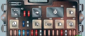
Fuse and relay diagram 2107
On newer “sevens” a block with 17 fuses and 6 relays is installed. VAZ 2107 fuses on the “new” unit protect the following electrical circuits and devices:
- Reversing lamps, heater fan, rear window defroster warning lamp and relay, rear wiper motor and rear washer pump.
- Electric motor for front wipers.
- Reserve socket.
- Reserve socket.
- Power supply for heated rear window.
- Clock, cigarette lighter, power socket “carrying”.
- Signal and radiator fan.
- Turn signal lamps in emergency mode.
- “Fog lights” and a relay that regulates the voltage of the on-board network.
- Instrument panel lamps.
- Brake light bulbs.
- Right high beam headlight.
- Left high beam headlight, high beam warning lamp.
- Side lights (rear right, front left), license plate and engine compartment lighting.
- Side lights (rear left, front right), glove compartment and cigarette lighter lamps.
- Low beam (right lamp).
- Low beam (left lamp).
The block relays perform the following functions:
- Heated rear window relay.
- Headlight cleaner and washer relay.
- Signal relay.
- Cooling system electric fan relay.
- High beam relay.
- Low beam relay.
The fuse block of the VAZ 2107 (injector) is no different from the block on the carburetor “seven”. Injection models are simply equipped with an additional relay and fuse box installed in the cabin under the glove compartment. The block includes three relays - the “main” relay, the fuel pump relay and the fan relay.
How to find the reason for the battery not charging
The first sign of a lack of charging is the warning light on the instrument panel coming on or if the voltmeter needle is not in the green zone when the engine is running. You can more accurately check the voltage on the battery using a multimeter.
When the engine is running, the voltage on the battery should be – 13.9±0.3 V. If the battery is not charging, the voltage will be approximately 12 V.
Warning: to avoid damage to the ECU and regulator relay, do not remove the battery terminals while the engine is running.
Increased or decreased voltage of the on-board network harms the battery. In the first case, the electrolyte boils away, in the second, it is discharged, which leads to failure of the battery.
To find the problem and fix it, you will need the following tools and devices:
- control lamp 12 V;
- multimeter;
- knife;
- flat screwdriver;
- pliers;
- sandpaper.