The “sevens”, like most modern cars, use a single-wire circuit for supplying electricity to electrical equipment. The other terminal of the consumer is always connected to the ground of the machine to which the negative terminal of the battery is connected. This solution allows not only to simplify the design of the on-board network, but also to slow down corrosion.
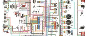
VAZ-2107 diagram: first option
Full size wiring diagram:
For carburetor systems
There are still many VAZ 2107 cars in use on the roads with a carburetor supply of the fuel mixture. As in the injector, engine cooling occurs thanks to the radiator and fan, only the process is regulated by a fan sensor.
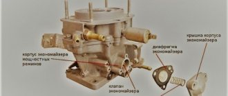
Location and principle of operation
On older cars, additional cooling begins when the antifreeze reaches a certain temperature, usually 92 °C (there are differences for individual sensors). Carburetor systems are equipped with 2 coolant sensors - one to regulate fan operation, and the second sends readings to the driver’s instrument panel.
The sensor that turns on the fan is located on the bottom of the radiator panel, on the right side. To see it, you need to lift the hood and on the back you can see a “nut” with wiring. Usually these are modifications of the TM-108.
The principle of operation is to change the volume of the working fluid of the sensor when the temperature of its working fluid fluctuates. Inside the thick-walled steel housing is a working mixture covered with a flexible plate attached to a pusher that connects the contacts when the sensor is triggered.
In the steel case, the sensor heats up evenly, the working fluid expands and the contacts are connected, the fan is activated.
There are several modifications of the devices - TM108; TM108-10; 661.3710. The first is designed for operating temperatures: 92–99 °C (contact activation and disconnection). The second is designed for colder operating conditions: 87–92 °C. These sensors operate in a circuit with an additional relay and can withstand a current of 1 A. If a relay contact is not provided and the fan is connected directly to the sensor, then the latest 16 A model is used.
Electrical diagram VAZ-2107 carburetor
Electrical diagram of VAZ 2107, 21074 produced in 1988-2001 with generator 37.3701
- block headlights
- side direction indicators
- accumulator battery
- starter relay
- carburetor electro-pneumatic valve
- carburetor microswitch
- generator 37.3701
- gearmotors for headlight cleaners *
- Fan motor switch sensor
- engine cooling fan motor
- sound signals
- distributor
- spark plug
- starter
- coolant temperature gauge sensor
- engine compartment lamp
- low oil pressure warning sensor
- low brake fluid level indicator sensor
- windshield wiper motor
- carburetor electro-pneumatic valve control unit
- ignition coil
- headlight washer pump motor *
- windshield washer pump motor
- mounting block
- windshield wiper relay
- hazard warning and direction indicator relay
- brake light switch
- reverse light switch
- ignition relay
- ignition switch
- three lever switch
- hazard switch
- socket for portable lamp**
- heater fan switch
- additional resistor for the electric motor of the heater (stove)
- rear window heating indicator lamp
- low brake fluid level warning lamp
- signaling unit
- heater fan electric motor
- glove compartment lamp
- light switches on the front door pillars
- switches for warning lights of open front doors ***
- front door open warning lights ***
- connection block
- cigarette lighter
- watch
- instrument light switch
- diode for checking the serviceability of the low brake fluid level indicator lamp
- fuel level indicator
- fuel reserve indicator lamp
- speedometer
- turn signal indicator lamp
- carburetor choke indicator lamp
- battery charge indicator lamp
- carburetor choke warning switch
- instrument cluster
- econometrician
- light switches on the rear door pillars
- coolant temperature gauge
- tachometer
- indicator lamp for parking brake activation (“handbrake”)
- low oil pressure warning lamp
- high beam indicator lamp
- indicator lamp for turning on external lighting
- voltmeter
- Parking brake indicator switch (“handbrake”)
- outdoor light switch
- rear window heating switch with backlight
- rear fog light switch with on/off indicator *
- fog light circuit fuse
- lampshade ****
- tail lights
- level indicator and fuel reserve sensor
- connectors for connecting to the rear window heating element *
- license plate lights 2107
Wiring diagram VAZ-2107 carburetor - full view:
Method three - perfect fans
To improve the cooling of the VAZ 2107, you can use more modern ones instead of a standard electric fan. Those that are installed on cars of the Kalina and Priora models are perfect. An electric fan with eight blades will work especially well. The air flow from it will be much stronger, therefore, the radiator honeycombs will cool down faster.
You can even get carried away with the issue of improving cooling and install two such fans. But does this make sense? It would be better then to completely clean the cooling system from the inside, replace all the pipes, and install a pump with an improved impeller. And finally, change the radiator. This will be much more effective than making a huge “collective farm” around the radiator.
All the main electrical circuits and modifications for connecting the liquid cooling fan (CO) in VAZ cars of various models are provided. What is the essence of VO’s work? An electric motor with an impeller on a shaft is installed inside a rectangular metal frame, with which it is attached to the back of the radiator. When voltage (12 V) is applied to the contacts of the drive, it begins to work, rotating the blades and creating a directed stream of air, which, in fact, cools the antifreeze or antifreeze.
If the cooling fan does not work, do not rush to contact a car service. You can determine the cause of the malfunction yourself. Moreover, for this it is not at all necessary to have special skills - just study the reference material from the site
and follow the instructions to check/replace it.
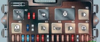
Mounting block connection diagram
P1 — relay for turning on the heated rear window; P2 - relay for turning on the headlight cleaners and washer; P3 - relay for turning on sound signals; P4 - relay for switching on the electric motor of the engine cooling system fan; P5 - headlight high beam relay; P6 - low beam headlight relay; A - the order of conditional numbering of plugs in the mounting block blocks. The outer number with the letter “Ш” in the plug designation is the block number, and the inner number is the conventional number of the plug.
For injection system
Forced fuel supply in the "seven" for the Russian market began to be used in 2006. In these car models, the fan operation and other functions are performed by the ECU. On the VAZ 2107 injector, the signal about the antifreeze temperature comes from the coolant temperature sensor, which is located on the right side of the engine cylinder block.
The data is processed by the ECU, which outputs a signal to the control relay to turn on the cooling - circuit diagram. The fan switching sensor is not needed on VAZ 2107 injection systems; it is replaced by a thermistor sensor, and control functions are assigned to the controller.
In any “seven”, to protect the fan from short circuit, there is a fuse F7 located in the mounting block.
Operation of the coolant temperature sensor for the injection system
Usually, turning on the fan on a VAZ 2107 is accompanied by a noise that the driver hears while sitting behind the wheel. A prolonged absence of sound from the device when driving around the city in the summer may indicate a malfunction in the cooling system, which can lead to antifreeze boiling and damage to engine components. The driver must react quickly to such defects so as not to spoil the “heart” of his car.
One of the possible malfunctions in the engine cooling cycle may be a breakdown of the coolant temperature sensor. In addition to the cooling system, it is responsible for the correct supply of the air-fuel mixture to the engine and its inclusion in idle mode.
The sensor that affects the operation of the VAZ 2107 injector fan consists of a semiconductor thermistor with two terminals, soldered into a housing with a thread that is screwed into the wall of the cylinder block. A constant voltage of 5 V is supplied to the device. As the temperature of the antifreeze increases, the resistance of the thermistor decreases and vice versa. At the input to the computer, passing through a resistor, the voltage drops as the coolant temperature increases to a certain level, after which the controller gives a signal to turn on the cooling.
How to check and install a new one
Checking the sensor responsible for turning on the fan does not require much effort. The following signs may serve as grounds for verification:
- The “Check Engine” light on the instrument panel is on.
- The fan operates continuously or is turned off.
- Low idle torque.
- Coolant overheating.
Schemes of individual blocks of the seven
Power supply system
Power plant starting system
1 - starter; 2 - relay; 3 — ignition switch; 4 - battery
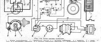
Ignition system
1 - generator; 2 — ignition switch; 3 - distributor; 4 - breaker; 5 — candles; 6 - coil; 7 - battery
Contactless ignition system
External and internal lighting
Windshield wipers and washers
1 — electric motors of the windshield wiper; 2 — washer motor; 3 — mounting block; 4 — ignition switch; 5 - washer switch
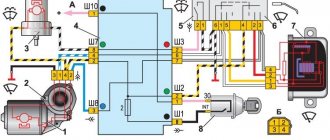
Cooling Fan
1 — fan electric motor; 2 - sensor; 3 — mounting block; 4 - ignition relay; 5 - ignition switch.
Control circuit modernization
The cooling fan on the top ten turns on at a temperature of 100-105°C, while the normal operating temperature of the engine is 85-90°C, so the fan turns on when the engine overheats, which naturally has a negative effect.
This problem can be solved in two ways: adjust the switch-on temperature in the “brains” or make a button. We'll focus on the second one. Turning on the fan from the button is very convenient: if you get into a traffic jam, turn it on, drive out, turn it off, and no overheating occurs.
A button for selecting the fan operating mode was installed in the cabin (always off, constantly on, automatically turned on via a sensor) - this “tuning” is not mandatory, but will be a very useful addition.
There will be a large current at relay contacts 87, 30, on the wire from the battery to the fuse and the fan ground, and therefore we must use wires there with a cross-section of at least 2 mm, otherwise the thinner wire will not withstand it and will burn out.
Wires for connecting electrical appliances
| Connection type | Section, mm2 | Insulation color |
| Negative terminal of the battery - vehicle ground (body, engine) | 16 | Black |
| Starter positive terminal - battery | 16 | Red |
| Positive contact of the generator - plus battery | 6 | Black |
| Generator - black connector | 6 | Black |
| Terminal on the generator “30” – white MB block | 4 | Pink |
| Starter connector “50” – starter relay | 4 | Red |
| Starter Start Relay - Black Connector | 4 | Brown |
| Ignition switch relay - black connector | 4 | Blue |
| Ignition switch output “50” – blue connector | 4 | Red |
| Ignition switch connector “30” – green connector | 4 | Pink |
| Right headlight plug - ground | 2,5 | Black |
| Left headlight plug - blue connector | 2,5 | Green, gray |
| Generator output “15” – yellow connector | 2,5 | Orange |
| Right headlight connector - ground | 2,5 | Black |
| Left headlight connector - white connector | 2,5 | Green |
| Radiator fan - ground | 2,5 | Black |
| Radiator Fan - Red Connector | 2,5 | Blue |
| Ignition switch output “30/1” – ignition switch relay | 2,5 | Brown |
| Ignition switch contact “15” – single-pin connector | 2,5 | Blue |
| Right headlight - black connector | 2,5 | Grey |
| Ignition switch connector “INT” – black connector | 2,5 | Black |
| Six-pin block of the steering column switch - “ground” | 2,5 | Black |
| Two-pin block of the steering column switch - glove box illumination lamp | 1,5 | Black |
| Glove compartment light - cigarette lighter | 1,5 | Black |
| Cigarette lighter - blue block connector | 1,5 | Blue, red |
| Rear window defroster - white connector | 1,5 | Grey |
Useful: VAZ 2110 diagram
Method two - electric
If you have a new car, an injector and an electric fan are installed, is it worth spoiling it with a forced impeller? It would be somewhat more reasonable to leave the electric fan, but make a backup way to turn it on using a button. Purchase several items and materials from the store:
- New sensor (if the old one has become unusable).
- Electromagnetic relay with normally open contacts.
- Red wire with a cross section of 0.75 square meters. mm.
- A button for installation in the dashboard of a VAZ 2107 (preferably backlit).
- Heat shrink insulation.
- Female connectors and relay socket.
The connection diagram is shown in the photo. First of all, turn off the fan and change the sensor for turning it on. Then you assemble the circuit.
Please note that newer vehicles use sensors that can handle very high currents. But despite this, they still burn out. Sudden loads still quickly damage it. What to do? There is only one way out - to reduce the current at the sensor terminals. To do this, introduce an electromagnetic relay into the circuit. Now the chance of sensor failure is reduced. But the chance of relay failure becomes higher. True, it will be easier to change it.
Install a button to force the fan on in the dashboard and stretch two wires from it - one can be connected directly to ground, and the second to the sensor output. It turns out that your button and sensor contacts are connected in parallel. Therefore, if the sensor fails, you can turn on the electromagnetic relay with a button.
Car wiring diagram
1 – radiator fan drive motor; 2 – relay and fuse block (mounting block); idle speed sensor; 4 – engine control unit; 5 – potentiometer; 6 – set of spark plugs; 7 – ignition control unit; 8 – electronic crankshaft sensor; 9 – electric fuel pump; 10 – tachometer 2107; 11 – lamp for monitoring the health of electronic systems; 12 – ignition system control relay; 13 – speed sensor; 14 – diagnostic connector; 15 – set of injectors; 16 – adsorber solenoid valve; 17, 18, 19 – fuse block protecting the injection system circuits; 21 – electronic fuel pump control relay; 22 – electronic relay for controlling the intake pipe heating system; 23 – intake pipe heating system; 24 – fuse protecting the heater circuit; 25 – electronic oxygen level sensor; 26 – cooling system temperature control sensor; 27 – electronic air damper sensor; 28 – air temperature sensor; 29 – pressure control sensor.
Replacing an electric fan in a car
- We park the car on a flat surface and immobilize it with the parking brake.
- Open the hood and disconnect the negative terminal.
- Using a 10mm wrench, unscrew the fastenings of the air filter housing.
- Using a screwdriver, loosen the air duct clamp on the air flow sensor and remove the corrugation.
- We unscrew the screws securing the cover of the air filter housing and remove the filter element.
- Using a size 8 wrench, unscrew the air intake mount and remove it.
- Using a 10mm wrench, then an 8mm wrench, unscrew the nuts securing the fan casing around the perimeter (6 pieces in total).
- Disconnect the wire block on the fan connector.
- Carefully remove the fan casing along with the drive.
- Using a 10mm wrench, unscrew the 3 bolts holding the electric motor to the casing.
- We put a new one in its place.
- We install the structure in place, fix it, and connect the connector.
- We carry out further installation in the reverse order.
Fuse and relay diagram 2107
On newer “sevens” a block with 17 fuses and 6 relays is installed. VAZ 2107 fuses on the “new” unit protect the following electrical circuits and devices:
- Reversing lamps, heater fan, rear window defroster warning lamp and relay, rear wiper motor and rear washer pump.
- Electric motor for front wipers.
- Reserve socket.
- Reserve socket.
- Power supply for heated rear window.
- Clock, cigarette lighter, power socket “carrying”.
- Signal and radiator fan.
- Turn signal lamps in emergency mode.
- “Fog lights” and a relay that regulates the voltage of the on-board network.
- Instrument panel lamps.
- Brake light bulbs.
- Right high beam headlight.
- Left high beam headlight, high beam warning lamp.
- Side lights (rear right, front left), license plate and engine compartment lighting.
- Side lights (rear left, front right), glove compartment and cigarette lighter lamps.
- Low beam (right lamp).
- Low beam (left lamp).
The block relays perform the following functions:
- Heated rear window relay.
- Headlight cleaner and washer relay.
- Signal relay.
- Cooling system electric fan relay.
- High beam relay.
- Low beam relay.
The fuse block of the VAZ 2107 (injector) is no different from the block on the carburetor “seven”. Injection models are simply equipped with an additional relay and fuse box installed in the cabin under the glove compartment. The block includes three relays - the “main” relay, the fuel pump relay and the fan relay.
Electric radiator cooling fan (forced)
To prevent a breakdown of the VAZ 2107 fan sensor from causing problems, you can organize forced cooling without replacing the standard electric fan with an impeller mounted on the pump pulley. To do this, it is enough to ensure that the fan is turned on with a button. You will need the following parts and materials:
You will also need a new fan sensor if the old one is faulty. Serviceability can be checked with an ohmmeter or continuity tester. If the fan does not turn on when the lower part of the radiator heats up, it must be replaced.
First you need to reduce the current passing through the contacts of the thermal relay that controls the fan. To do this, the VAZ 2107 fan switching circuit must be changed so that it is powered not directly from the sensor, but through an additional relay. In this case, the contacts of the fan sensor (thermal relay) will not burn out, and if the additional relay fails, it will be much easier to replace the latter.
It is also necessary to connect the fan switch button so that when turned on, it duplicates the sensor, supplying voltage to the relay coil when turned on. In this case, if the sensor breaks down, you can manually turn on the VAZ cooling fan and protect the engine from overheating.
Modifications of the VAZ-2107 car
VAZ-2107 . Basic version of the sedan, with an 8-valve carburetor VAZ-2103 engine, 1.5 liters.
VAZ-2107-20 . The same VAZ-2107, but with a 1.5-liter VAZ-2104 injection engine that meets the Euro-2 environmental standard.
VAZ-2107-71 . The car for the Chinese market was equipped with a VAZ-21034 engine, with a volume of 1.4 liters and a power of 66 horsepower, specially tuned for A-76 gasoline. The pistons were taken from a VAZ-2108.
VAZ-21070 . Modification of a car with an 8-valve, carburetor VAZ-2103 engine, volume 1.5 liters.
VAZ-21072 . Modification with an 8-valve carburetor VAZ-2105 engine, volume 1.3 liters.
VAZ-21073 . An export modification for the European market, which was equipped with a 1.7-liter injection engine with a capacity of 84 horsepower. The engine of this car had a catalytic converter that satisfied environmental protection requirements.
VAZ-21074 . Modification with an 8-valve, carburetor VAZ-2106 engine, volume 1.6 liters.
VAZ-21074-20 . Modification with a 1.6-liter VAZ-21067-10 injection engine, which complies with the Euro-2 environmental standard
VAZ-21074-30 . Like the previous model, but with a VAZ-21067-20 engine, which meets the Euro-3 environmental standard
VAZ-210740 . Modification produced in 2010, equipped with a VAZ-21067 injection engine with a catalyst. Engine capacity is 1.6 liters, power is 72.7 horsepower.
VAZ-21076 . Export modification with a VAZ-2103 carburetor engine.
VAZ-21077 . Export modification with right-hand drive for the UK market. The car was equipped with a VAZ-2105 carburetor engine with a volume of 1.3 liters.
VAZ-21078 . Another export modification for the UK, but with a 1.6-liter VAZ-2106 carburetor engine
VAZ-121079 . The modification, developed specifically for the needs of the Ministry of Internal Affairs and the KGB, was equipped with a powerful VAZ-413 rotary piston engine with a volume of 1.3 liters and a power of 140 horsepower.
VAZ-2107 ZNG . The car is equipped with an 8-valve, fuel-injected VAZ-21213 engine with a volume of 1.7 liters.
Video - connecting and checking VO
CLICK HERE AND OPEN COMMENTS
From a relay (from the forced on button) on a spiral from a classic stove, then parallel to the TM-108-10 into new “female” wires, respectively, VO turns 1.5 (through one spiral) and 2 times (through two in series ), as a result, the VO is not audible, does not vibrate and does not break the fan bearings, it is enough in a traffic jam and around the city, it does not go beyond 90g, when slipping, the TM-108-10 will turn on itself (that is, there was 8 volts through the spirals, the TM-108 closed and it became 14, since it is connected in parallel.) Works for 3 years on carb 2110.
Source
Injector maintenance
Since the injection power system is quite complex, during the operation of the car there is a need to eliminate failures and failures. You can service the car yourself if you have a detailed diagram. In particular, engine management systems:
Wiring diagram of electrical connections of ECM VAZ 21074
To troubleshoot you need:
- availability of electronic testers (their price is low - you should definitely buy them);
- adapters through which the tester is connected to the diagnostic connector.
By comparing the measurement results with operating parameters, you can easily identify an electrical circuit operating with deviations. And only then, when analyzing it, detect a non-working device: sensor or wiring.
Additionally, read the article Wiring - VAZ 2109 - injector: new engines in an old body.
Starter solenoid relay
The starter relay is called a pull-in relay. This is due to the principle of its operation - it performs the function of connecting the starting device to the electrical circuit and connecting its armature to the crankshaft. It happens like this: when no current is supplied to the windings of the device, its armature, under the action of the return spring, remains in the forward position. The same spring, through a special fork, holds the Bendix gear, preventing it from engaging with the crankshaft flywheel ring.
By turning the key in the ignition, we supply current to the winding of the device. Under the influence of an electromagnetic field, the armature is fed back (pulled into the housing), closing the starter power contacts. The Bendix gear also moves, engaging with the flywheel. At the same moment, the retracting winding is turned off, and the holding winding comes into play. The force from the starter shaft is transmitted through the gear to the flywheel, causing the crankshaft to rotate until we no longer hold the ignition key in the start position.
What functions does the solenoid relay perform:
- Protects the starter from shorting contacts in the ignition.
- In order to turn off the power to the starter in a situation where the engine is running and the key shows the “starter” mode.
- Provides relief of contacts in the ignition switch.
When the engine starts, voltage from the generator goes to the relay coil. Then the gears of the drive system begin to work, due to which a magnetic field is created. The flywheel of the propulsion system is working. The gear begins its work thanks to the holding winding, while the bolts are closed. When the key is returned to the ignition switch, the winding is de-energized, thus disconnecting the gear and flywheel. This scheme applies to modern cars, including VAZ models.
If the starter makes a loud noise, the pole or starter could be loose. In the first situation, strengthen the fastening by tightening the screw, and in the second, secure the starter. If you disassemble the starter and see that the clutch is starting to slip, then the only thing you need to do is replace the starter drive.
Check and replacement
If you suspect that the engine is overheating and there is no sound from the fan for a long time, it is necessary to determine the malfunction. If the wiring is shorted, the device may fail or the fuse may blow.
Checking the device is easy. You need to remove the wiring from the sensor, turn on the ignition key and connect the ends. If the cooling works, then there is a problem with the device and it needs to be replaced. It happens that cooling turns on at temperatures higher than those indicated on the sensor body, which also indicates its malfunction.
To replace it, you will need to drain the antifreeze or rush to screw in a new sensor, spilling a little coolant. The engine must be cold. You can unscrew it with a wrench or an adjustable wrench. It is better to substitute some kind of container and use a wrench to undermine the housing nut. Then carefully unscrew the thread by hand, pressing it against the socket. Move the old device aside and quickly press it with your finger, maybe some kind of plug, on the hole in the radiator. Carefully screw in the purchased sensor and connect the wiring.