03/04/2022 3,862 VAZ 2107
Author: Ivan Baranov
In any case, car optics must be in working order, since the safety of the car depends on it. Especially when it comes to rear lights, because it is through them that drivers of cars walking behind can learn about the maneuvers that the car is about to make. For what reasons do the rear lights of the VAZ 2107 not work and how to replace them - we will talk about this below.
[Hide]
INSTALLATION OF LIGHTING DEVICES
Installing components on a VAZ 2107 car will not cause any particular difficulties.
The procedure is as follows: Open the trunk, use a screwdriver to remove the lamp cover that closes it from the inside. Use a wrench to unscrew the fastening nuts and unplug the electrical connector. Carefully remove the flashlight unit from its seat and clean it of dirt with a rag. We install new taillights instead of the old ones and secure them, after inserting a sealing gasket.
Upon completion of the installation of the lights, we connect them and check their functionality in all modes. The installation of new lighting devices on a VAZ 2107 car that complies with regulatory documents does not require registration.
Tuning
LADA-2107, along with other “classic” models, is one of the most tuned Russian-made cars. Its cheapness, on the one hand, and outdated design, on the other, force many owners over time to make efforts to modernize the car.
For example, installing hydraulic compensators on the engine results in a noticeable reduction in engine noise and an increase in timing belt life. We also offer ready-made kits for replacing rear drum brakes with disc brakes.
Due to the large volume of classic cars in use, manufacturers of spare parts offer a lot of finished industrial products to improve consumer properties, and even conveyor suppliers offer “improved” products to replace their own components (for example, a heater motor on bushings from the factory - change to a motor with bearings). The “classics” segment probably has the widest selection of spare parts that differ from the factory equipment.
Purpose of car rear lights
Any modern car - both cars and trucks, as well as trailers and semi-trailers - are equipped with rear lights. These simple lighting devices perform signaling and warning functions for motorists driving behind:
- Brake alarm;
- Turn signal;
- Reverse alarm;
- In the dark - notification about being on the road.
All these problems are solved with the help of several lamps of different colors, having a specific location
The lamps turn on only in a certain situation (when braking, making a maneuver, engaging reverse, in the dark), and motorists driving behind are warned about a change in the situation on the road (that is, that the car ahead is braking, is about to turn or change lanes, etc. .d.), or that it is necessary to be careful (at night, keep a distance from the car driving ahead)
Housing VAZ-2115 outer rear right lamp DAAZ
Thus, tail lights are one of the simplest and most effective means of ensuring road safety, which is why they are provided on all vehicles, regardless of their type and purpose.
Brake lights do not work on VAZ 2105, 2107 cars
The reasons for brake lights not working on VAZ 2105, 2107 cars can be either a banal bulb burnout or a short circuit in the wiring. Let's look at the most common faults that lead to their failure, as well as how to consistently identify the cause.
The bulb in the rear light socket has burned out
One or two light bulbs can burn out at once. Moreover, visually they may look like workers. We replace the faulty lamp with a known good one and see if it lights up or doesn’t light up. The P21W bulb can be taken from the reversing light or from the turn signal in the same rear light. We replace faulty light bulbs with new ones.
The contacts in the rear brake light sockets have oxidized
Turn the light bulb in the socket several times to remove the oxidized layer. A more radical repair would be to sand the contacts in the cartridge with sandpaper.
The contacts in the rear light wire blocks have oxidized
We remove the block and clean the contacts in it and the contacts on the rear light board. The red wire is responsible for supplying current to the brake lights (to both the right and left lights).
Fuse blown
Brake lights on VAZ 2105, 2107 cars are powered through fuse No. 11 (F11) 10A in the mounting block. In addition, it also has interior lighting. So, if the “stops” and the lamp do not work at the same time, the fuse has definitely blown. Replace the burnt fuse with a new one. Subsequently, it will be necessary to find out the reason for the blown fuse, since there may be a short circuit.
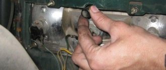
Brake light switch sensor faulty
It is located under the brake pedal. When the driver presses the pedal, the sensor contacts are closed, and current flows to the brake lights and into the rear lights. The electric current comes to the sensor through the red and white wire from the fuse mounting block, and goes to the “stops” along the red wire, also through the mounting block. It is necessary to remove the wires from the sensor, connect them together with a piece of wire, turn on the ignition and see if the brake lights are on. If they suddenly light up, change the sensor-switch.
For a more thorough check, use a test lamp or tester to check for the presence of current in the red-white wire. Suddenly there is a break in it. Current is supplied to it from the 11th fuse in the mounting block.
Burnt out contact tracks on the rear light boards
Visually inspect the rear light boards. If necessary, check the integrity of the tracks using a test lamp or tester. You can solder wires onto a faulty track and thereby restore its functionality.
No "mass"
The negative wires come from the taillight plugs (black wire) and are attached to the body. The fastening of the wires to the body should be checked for oxidation.
The wiring blocks of the mounting block have come off, or their contacts have oxidized
Clean the contacts in the blocks (you can simply remove and reinstall them several times) and make sure they fit securely in the mounting block.
Open or short circuit in wiring
Check the main components of the brake light wiring diagram for short circuits or open circuits using the diagram below
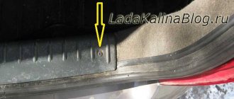
Special attention should be paid to the red wire in the wiring harness to the brake lights. It stretches across the entire car along the right threshold
It may fray or burn out during welding work.
It may fray or burn out during welding.
Electrical connection diagram for brake lights on a VAZ 2105; Electrical connection diagram for brake lights and parking brake on a VAZ 2107 car.
The plus in the brake light connection system comes from terminal “30” of the generator. Minus – black wires in the rear light plugs connected to the body.
Notes and additions
— It should be noted that the brake lights only light up on a vehicle with the ignition on.
Car wiring diagram
1 — radiator fan drive electric motor; 2 - relay block and fuses (mounting block); minimum sensor; 4 — engine control unit; 5 - potentiometer; 6 — a set of candles; 7 — ignition control unit; 8 — electronic crankshaft sensor; 9 — electric fuel pump; 10 — tachometer 2107; 11 — lamp for monitoring the health of electronic systems; 12 — ignition system control relay; 13 — speed sensor; 14 — diagnostic connector; 15 — set of injectors; 16 — adsorber solenoid valve; 17, 18, 19 - fuse block that protects the injection system circuits; 21 — relay for electronic control of the fuel pump; 22 - electronic relay for controlling the heating system of the suction pipe; 23 — inlet pipe of the heating system; 24 - fuse protecting the heater circuit; 25 — electronic oxygen level sensor; 26 — cooling system temperature control sensor; 27 — electronic air damper sensor; 28 — air temperature sensor; 29 — pressure control sensor.
How to troubleshoot?
The most common reasons why the brake light on a VAZ 2114 does not work are the following factors:
- Fuse failure.
- Broken wires in one of the sections of the circuit.
- Limit switch faulty.
- Bulbs burn out.
- Oxidation of contacts in lamp sockets.
- Damage to the contact board.
The most common and at the same time the most easily removable of the above reasons is a blown fuse. To identify such a malfunction, you need to examine the fuse box. A 10-amp fuse F3 is responsible for the brake lights, which also protects the ignition switch, computer and interior lighting.
Malfunctions in the operation of the latter may also indicate a malfunction of the stop fuse (and in this case, troubleshooting should begin with the block). If it turns out that the fuse has blown, then you should replace it with a new, similar one.
A new fuse installed in place of a failed one must be designed for exactly the same maximum current. If it is less, the fuses will blow more often, and if it is more, the protected device itself may burn out.
READ Hyundai Creta Exclamation Mark Illuminated
The problem may also be in the fuse block itself - sometimes the tracks on its printed circuit boards burn out or the contact legs oxidize. In order to check its serviceability, it is enough to measure the voltage at the contacts of the newly installed fuse.
Another common reason why the brakes of a VAZ 2114 do not light up is a malfunction of the limit switch that turns on the signals. It is located on the brake pedal bracket and is always in working order, regardless of whether the car engine is turned on or not.
It works automatically when you press the pedal. In order to check its serviceability, it is enough to see whether the power supply is suitable for its contacts (on one of the contacts the presence of power must be constant). In addition, if you press the pedal and thus turn on the limit switch, you can measure the voltage at its connectors.
If there is no current at the switch contacts, you should check the wire going to the limit switch from the fuse box. If the test shows that the wire is faulty (there is a break), then it should be replaced with a new one and the test repeated.
Otherwise (if everything is in order with the wire), you should disconnect it (as well as the other wire suitable for the second connector) from the switch and connect directly. If after such an operation the brake light works, then the limit switch itself has failed and should be replaced.
You should purchase a new brake light limit switch that is exactly the same model as the failed one. Installing a different type of switch may result in incorrect signal operation.
Explanation of symbols
Knowledge of the definitions of the 2107 Lada electrical circuit will help you quickly locate the required wire, diagnose it, identify and fix the malfunction. Of course, when replacing the cabin filter or changing the oil, such information will not be useful, but in specialized matters, deciphering the symbols will significantly simplify the repair process.
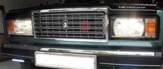
- 1 – headlights VAZ 2107;
- 2 – side turn signals;
- 3 – battery;
- 4 – starter activation relay;
- 5 – carburetor electro-pneumatic valve;
- 6 – internal carburetor switch;
- 7 – generator system 37.3701;
- 8 – gearmotors for headlight cleaners*;
- 9 – fan motor activation sensor;
- 10 – electric motor of the engine cooling fan;
- 11 – sound signals;
- 12 – ignition distributor;
- 13 – spark plugs;
- 14 – starter;
- 15 — coolant temperature indicator sensor;
- 16 – engine compartment lighting;
- 17 – critical oil pressure indicator sensor;
- 18 – warning lamp for insufficient brake fluid level;
- 19 – windshield wiper electric motor;
- 20 – power system valve control unit;
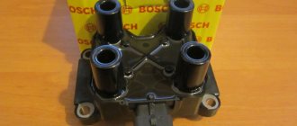
- 21 – ignition coil;
- 22 – electric motor of the headlight washer pump*;
- 23 – electric motor of the windshield washer pump;
- 24 – mounting block;
- 25 – windshield wiper relay;
- 26 – hazard warning and direction indicator relay;
- 27 – brake light switch;
- 28 – reverse lamp switch;
- 29 – ignition relay;
- 30 – ignition switch;
- 31 – three-lever switch;
- 32 – alarm switch;
- 33 – plug socket for a portable lamp**;
- 34 – heater heater fan switch;
- 35 – additional switch for the heater electric motor;
- 36 – indicator lamp for turning on the heated rear window;
- 37 – indicator lamp for insufficient brake fluid level VAZ;
- 38 – signaling unit;
- 39 – electric motor of the stove fan;
- 40 – glove compartment lighting lamp;
- 41 – lamp switches on the front door pillars;
- 42 – switches for warning lights of open front doors***;
- 43 – alarm lights for open front doors***;
- 44 – connecting block;
- 45 – cigarette lighter;
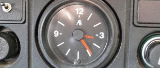
- 46 – hours;
- 47 – instrument lighting switch;
- 48 – diode for checking the serviceability of the warning lamp for insufficient oil pressure and brake fluid level;
- 49 – fuel level indicator;
- 50 – indicator lamp for insufficient gasoline level (fuel reserve);
- 51 – speedometer;
- 52 – control lamp for turning on the direction indicators on the dashboard;
- 53 – warning lamp for the carburetor air damper opening;
- 54 – indicator lamp for battery charge indicator;
- 55 – switch for signaling that the carburetor air damper is slightly open;
- 56 – instrument cluster;
- 57 – econometrician;
- 58 – lamp switches on the rear door pillars;
- 59 – coolant temperature indicator;
- 60 – tachometer;
- 61 – handbrake indicator lamp;
- 62 – low oil pressure indicator sensor;
- 63 – indicator lamp for high beam headlights;
- 64 – signaling device for turning on dimensions;
- 65 – voltmeter;
- 66 – parking brake warning switch;
- 67 – external lighting switch;
- 68 – rear window heating switch;
- 69 – rear fog light switch with on indicator*;
- 70 – fog light circuit fuse;
- 71 – interior lighting lamp****;
- 72 – rear lights;
- 73 – fuel level indicator and fuel reserve sensor;
- 74 – pads for connecting to the rear window heating element*;
- 75 – license plate lights.
How to change the reverse sensor on a VAZ 2107
Before replacing the sensor, it is advisable to clean the gearbox of dirt. If this is not done, it may get into the oil, which is located in the crankcase. Replacement of the VAZ 2107 reverse sensor is carried out in the following sequence:
- disconnect the wire tips from the sensor contacts;
- Using a 22mm wrench, unscrew the old sensor from the gearbox, removing it along with the metal washer;
Note: if the sensor is “stuck” and cannot be unscrewed using a wrench, you can try to unscrew it using a chisel and hammer
However, this must be done with extreme caution so as not to damage the gearbox housing, which is made of a fragile aluminum alloy.
- clean the sensor seat;
- put a new washer on the new sensor and screw it into the gearbox using a 22mm wrench;
- Place the wire ends on the sensor contacts.
Now you know how to change the reverse sensor on a VAZ 2107
After installing the new sensor, pay attention to how tightly the wire tips fit on the sensor contacts. They should not dangle or fall off
If necessary, tighten the tips using pliers. It is a good idea to clean the tips before placing them on the sensor contacts. This way you can be sure of reliable contact on this connection.
What is needed for replacement
To change the part, you only need two things: a 22mm wrench and a new reverse sensor with a metal washer-spacer. It is advisable to use a socket wrench with a long wrench. But, if you don’t find one, you can get by with a cap or even a carob.
Workflow Description
In order to complete the work, it is necessary to prepare everything necessary and ensure comfortable working conditions.
Preparation
As part of this stage, the following activities are performed:
If the low beam on a VAZ 2107 has disappeared and as a result of the check it is found that the lamps are to blame, then you should purchase new products. This model uses the AKG12-60+55 modification with an H4 socket; this marking indicates that the product has a power of 60 W for high beam and 55 W for low beam; you can purchase such an element at any store that deals in spare parts for domestic cars.
- The work must be carried out in a dry place with good lighting, the ideal solution is a garage, but you can even do it outside if the weather permits and there is no precipitation.
- No special tools are required, which is an undoubted advantage of this type of work.
The working process
Everything is quite simple and takes very little time:
A huge advantage of the work is that, unlike modern models, access to the headlights is not limited in any way; this greatly simplifies doing the work yourself and allows you to achieve the best result, since you are in complete control of the process.
Replacing the low beam lamp on a VAZ 2107 begins, as on any other car, by removing the terminal from the battery. Make it a rule to disconnect the battery when doing any work on the electrical part of the car, this will prevent problems that may arise from short circuits and damage to individual elements, and you will definitely not be electrocuted.
- If there is no low beam on a VAZ 2107 on only one side, then you can replace one lamp, although experts advise installing two at once, since the light may vary. One way or another, the work begins with any headlight that is convenient for you, first wipe the inside, since most often it is dirty and debris can get inside later.
- First of all, it is necessary to remove the plug, which covers the installation site of the light bulb and serves as protection against moisture and dirt getting inside the housing. This element is removed very simply: grab it and turn it counterclockwise until it comes off, usually this happens in half or even a quarter of a turn.
Then you need to remove the connecting block with the wires, this should be done very carefully: grab the connector body and pull in the direction from the base. If, then you can very easily break contacts, and you will also have to eliminate this problem.
After liberation, you can take out the old lamp, because it is no longer secured by anything
Please note that when removing the new unit and installing it in place, you must not touch the glass part, as this will cause the areas touched to burn. Handle the chuck and be careful to avoid problems
Assembly is carried out in reverse order, so there is no point in describing this process separately.
There is only one thing left - to check the operation of the system, and if everything is fine, then you can completely assemble the structure.
Total information
| Options | VAZ 2107 | VAZ 21074 | VAZ 2107-20 | VAZ 21074-20 |
| Weight of the equipped vehicle, kg | 1060 | 1060 | 1060 | 1060 |
| Payload, kg | 400 | 400 | 400 | 400 |
| Permitted maximum weight, kg | 1460 | 1460 | 1460 | 1460 |
| Ground clearance of a vehicle with a permissible maximum weight, with tires 175/70 R13, not less, mm: | ||||
| to the front suspension cross member | 162 | 162 | 162 | 159 |
| to the rear axle beam | 157 | 157 | 157 | 154 |
| Permissible weight of cargo on the additional (top) luggage rack, kg | 50 | 50 | 50 | 50 |
| Maximum speed, km/h: | ||||
| with permissible maximum weight | 148 | 148 | – | – |
| with driver and passenger | 150 | 150 | 150 | 150 |
| Acceleration time from standstill to 100 km/h, s: | ||||
| with driver and one passenger | 17 | 16 | 17 | 16 |
| with permissible maximum weight | 19 | 17,5 | – | – |
| Minimum turning radius along the track of the outer front wheel, m | 5,6 | 5,6 | 5,6 | 5,6 |
| The greatest rise overcome by a car with a permissible maximum weight without acceleration in first gear, % | 36 | 36 | 36 | 36 |
VAZ 21074 engine control system diagram
Wiring diagram of electrical connections of ECM VAZ 21074 - circuit elements. 1 — controller connector; 2 — mass air flow sensor; 3 — coolant temperature sensor; 4 — crankshaft position sensor; 5 — throttle position sensor; 6 — oxygen concentration sensor; 7 — speed sensor; 8 — ignition module; 9 — solenoid valve for purge of the adsorber; 10 — electric fan relay; 11 — electric fuel pump relay; 12 - main relay; 13 - fuse for the power circuit of the electric fuel pump relay: 14 - fuse for the power circuit of the main relay; 15 — fuse-link; 16-fuse protecting the constant power supply circuit of the controller; 17 - diode; 18 — idle speed regulator; 19 — nozzles; X1 - diagnostic block; X2 - connection block to the vehicle electrical system.
Fog lights
Driving a car in rain or snow can create a lot of trouble for the driver who is forced to drive the car in poor visibility conditions. In this situation, fog lights (FTL) come to the rescue, the design of which provides for the formation of a light beam that “spreads” over the surface of the roadway. Fog lamps are usually yellow, since this color tends to dissipate less in fog.
Fog lights are usually installed under the bumper, at a height of at least 250 mm from the road surface. The installation kit for connecting PTF includes:
- set of wires;
- relay;
- button.
In addition, a 15 A fuse will be required, which will be installed between the relay and the battery. The connection should be made in accordance with the diagram supplied with the installation kit.
The fog lights must be connected in accordance with the diagram supplied with the installation kit.
Electrical diagram for connecting VAZ-2107 headlights
The electrical circuit diagram for outdoor lighting includes:
- Block headlights with side lights.
- Engine compartment light lamp.
- Mounting module.
- Illuminated glove compartment.
- Instrument panel lighting.
- Rear lights with dimensions.
- Illuminated license plates.
- Outdoor lighting switch.
- Indicator lamp in the speedometer.
- Ignition.
- Conclusions A - to the generator, B - to the backlight lamps of devices and switches.
Headlights are part of the car's exterior lighting system, which is controlled by buttons on the dashboard
The operating diagram of the rear lights and fog lights consists of:
- Block lights.
- Mounting module.
- Three lever switch.
- External lighting switch.
- Fog light switch.
- Rear lights.
- Fuse.
- Indicator lamp for fog lights.
- High beam warning lamp.
- Ignition key.
- High beam (P5) and low beam (P6) relay.
The circuit for the rear lights and fog lights is mounted on a separate module
Understeering's shifter
The VAZ-2107 steering column switch is three-lever and performs the following functions:
- high and low beam control;
- turning on the direction indicators;
- windshield washer control.
The location of the switch allows the driver to control vehicle devices without being distracted from the road. The most typical malfunctions of the steering column switch (also called the tube) are considered to be failure of the contacts responsible for the operation of turns, low and high beams, as well as mechanical damage to one of the levers.
Group of contacts 53 in the connection diagram of the VAZ-2107 steering column switch is responsible for the windshield washer, the remaining contacts are for controlling the lighting devices.
Group of contacts 53 in the connection diagram of the VAZ-2107 steering column switch is responsible for the windshield washer system, the remaining contacts are for controlling the lighting devices
Headlight relays and fuses
Responsible for the protection of lighting fixtures are the fuses located in the new type block and are responsible for:
- F1 - reversing lamps;
- F8 - direction indicators in “emergency” mode;
- F9 - fog lights;
- F10 — instrument panel illumination;
- F11 - brake lights;
- F12 - high beam of the right headlight;
- F13 - high beam of the left headlight;
- F14 - dimensions (front left, rear right), license plate and engine compartment lighting;
- F15 — dimensions (front right, rear left), glove compartment lighting;
- F16 - low beam of the right headlight;
- F17 - low beam of the left headlight.
The VAZ-2107 fuse and relay box is located under the hood near the windshield opposite the passenger seat
The operation of lighting devices is regulated using a relay:
- 5 — high beam;
- 6 — low beam.
Daytime Running Lights
Daytime running lights (DRLs) should not be confused with running lights: they are lighting devices designed to improve daytime visibility. As a rule, DRLs are made with LEDs, which provide bright light and have a long service life. It is not recommended to turn on the DRLs at the same time as the low beam or fog lights. To install DRLs on your car, you don’t have to go to a service station; you can do it yourself
It is important to take into account that:
- lighting devices must be installed in accordance with the requirements of GOST R 41.48–2004;
- Not all DRLs are suitable for the “seven”. Many car owners install lights like Philips Led Daylight 9;
- most often, DRLs are placed on the bumper or air intake;
- lighting devices should be at a height of 250–1500 mm from the ground;
- the distance between the two visible edges of the devices must be at least 600 mm;
- DRLs can only be located at the front of the car, and the light beam must be directed only forward;
- The overall brightness of the light should be between 150–330 lumens.
The DRL connection diagram provides for the presence of a five-pin relay type M4 012–1Z2G.
To connect the DRL you will need a five-pin relay type M4 012–1Z2G
The relay is connected as follows:
- contact No. 30 must be connected to the ignition “plus”;
- No. 86 connects to the button for turning on the headlights and low beam;
- No. 87 remains unconnected;
- No. 85 - mass;
- No. 88 (87A) - output to DRL.
There are several options for connecting DRLs, one of which is designed to turn them off when the engine starts.
One of the DRL connection diagrams is designed to turn them off when the engine starts
In this case, the contacts are connected as follows:
- minus DRL goes to the body;
- plus - to relay contact No. 30;
- pin 87 is connected to the battery positive;
- contact 85 - with ground;
- contact 86 is connected to a reed switch, the second contact of which is connected to the positive terminal of the generator.
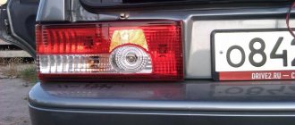
Accessories for modernizing rear lights
For such a mass model as the VAZ 2107, many small domestic and foreign companies produce many options for lighting equipment for tuning, which can be easily installed in standard places and do not require alteration of the body structure. Alternative taillights of the VAZ 2107 can be made using both incandescent lamps and LEDs. The latter are more expensive, but have a number of advantages:
- Less energy consumption. LEDs consume 10 times less energy than incandescent lamps of similar brightness.
- Fast response. Incandescent lamps do not light up immediately; they require time to warm up the coil, while LEDs begin to glow at full power immediately after voltage is applied.
- Higher information content of signals, achieved due to the original arrangement of light indicators.
- Increased brightness compared to standard devices.
Taillights for tuning the VAZ 2107 are presented on the market in a wide range. Conventionally, they can be divided into five groups:
- A sporty version featuring four round and two rectangular indicator lights. They can be arranged separately and placed in a plastic case, painted in the color of the car body.
- Skylain lights with three round indicators and two rectangular turn and brake indicators located above them. The lamp housings are made of transparent plastic with a chrome finish.
- The “eyelash” taillights are distinguished by their original shape and LED turn indicators, which are perfectly visible even in bright sunlight.
- Tinted rear lights designed specifically for those who love unusual lighting solutions. More powerful lamps installed in them ensure good visibility of signals even in bright light.
- LED lights of a classic design, the indicators in which are located similarly to the standard ones. They are popular due to their fast response and high signal brightness.
To install tuned taillights, it is enough to remove the standard taillights of the VAZ 2107 and install new ones in their place. The removal and installation procedure is described above, in the section “Tinting the rear lights of the VAZ 2107”.
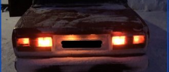
Dimensions of VAZ 2104, 2105, 2107 do not light up
On VAZ 2104, 2105, 2107 cars there are 4 side lights (dimensions): one in the front headlights and one in the rear lights. Failure of any of them to work is a fairly common occurrence. Let's look at the reasons for this malfunction - “why the lights on VAZ 2104, 2105, 2107 cars don’t light up.”
Symptoms of a malfunction: “VAZ 2104, 2105, 2107 dimensions do not light up”
One dimension, two dimensions (front or rear, right or left side, crosswise) or all of them may not work.
The side light bulb is burnt out
The most common reason. One light bulb, or several at once, can suddenly burn out. In some cases, it may be impossible to visually identify a burnt-out light bulb. Therefore, we replace the burnt out one with a known good one. You can use a similar one from a nearby headlight.
The contacts of the light bulb in the socket have oxidized
We rotate the light bulb in the socket several times to remove the oxidized layer and restore contact. In the future, you can clean everything with sandpaper.
Lost ground to headlights or taillights
Loss of contact with ground leads to failure of not only one size, but also the entire headlight or rear light.
The “negative” wires of the front headlights and rear lights with side lights on VAZ 2104, 2105, 2107 cars are attached to the car body. It is necessary to clean the mounting location to ensure good contact with ground. Usually the negative wire is the black wire from the headlight connection block, attached to the body next to the headlight or tail light.
Broken contact in the headlight or rear light connection block
Either it has oxidized or the block is not attached tightly. In such a situation, either one side lamp or the entire headlight may not light. We put on and take off the pad several times to restore contact.
The track in the rear light board has crumbled
During long-term use of the vehicle, or if a low-quality part is installed, the track to the side light lamp socket in the rear lights may shed (burn out).
Contact is broken in the connecting blocks of the relay and fuse mounting block
Check the pads Ш12 (Х12), Ш13 (Х13), Ш9 (Х9), Ш6 (Х6) of the mounting block. Or Ш2 (Х2) - terminals 1 and 3 if all the dimensions do not light up.
The fuse in the mounting block has blown
If fuse No. 14 (F14) is blown, the side lights in the front left headlight and rear right headlight will not light. If No. 15 (F15), then the marker in the front right headlight and rear left lamp will not light up, that is, crosswise.
The fuses must be replaced with serviceable ones and the cause of their burnout must be determined in the future. There may be a short circuit in the electrical circuit.
The external lighting switch on the instrument panel is faulty
All dimensions will not light up. Remove the switch and remove the wire block from it. Connect the leads of the black and yellow-red wires with a piece of wire. Turn on the ignition. If the dimensions light up, the switch is faulty and must be replaced.
“Open” in the electrical circuit connecting the side lights
It is necessary to check the sections of the circuit responsible for the non-burning light using the connection diagram. Read more: “How to find an open circuit in a car’s electrical circuit.”
Scheme for switching on the external lighting of a VAZ 2105 car
Wiring diagram for dimensions 2107.
Connection diagram of dimensions (external lighting) of a VAZ 2107, 21074 car
Mounting block connection diagram
P1 — relay for turning on the heated rear window; P2 - relay for turning on headlight cleaners and washers; P3 - relay for turning on sound signals; P4 - relay for switching on the electric motor of the engine cooling system fan; P5 - high beam relay; P6 - low beam headlight relay; A - the order of conditional numbering of pins in the blocks of the mounting block. The outer number with the letter “Ш” in the plug designation is the block number, and the inner number is the conditional number of the plug.
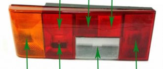
Design and characteristic malfunctions of the rear lights of the VAZ-2107
Structurally, the rear light of the VAZ-2107 car consists of:
- left and right diffusers;
- left and right conductors;
- two 4 W lamps and two sockets for them;
- six lamps with a power of 21 W and six sockets for them;
- four M5 nuts.
The rear light of the VAZ-2107 consists of diffusers, conductors, lamps and sockets
The brake light and side lights on the rear light should be red, the turn signal should be orange, and the reverse light should be white. The most typical malfunctions of the rear lights of the VAZ-2107:
- lack of mass on the lantern;
- lamp burnout;
- oxidation of contacts;
- broken or frayed wiring;
- failure of connector contacts, etc.
No mass
One of the reasons that the tail light does not work may be the lack of weight on it. You can check the integrity of the ground wire visually or by ringing it with a tester. The ground wire in the standard configuration of the VAZ-2107 is usually black, and it occupies the extreme position on the connector block. It is followed by wires:
- brake light (red);
- side lights (brown);
- fog lamps (orange-black);
- reverse lamps (green);
- direction indicator (black and blue).
The wires on the connector go in a certain sequence and have their own colors
Lamp burned out
The most common malfunction of rear lights is the burnout of one of the lamps. In this case you will need:
- Remove the plastic plug from the trunk side, which is secured with four plastic screws;
The plastic plug for the rear light of the VAZ-2107 is secured with four plastic screws
- Using a 10mm wrench, unscrew the 4 nuts on which the flashlight is attached;
The nuts securing the rear light of the VAZ-2107 are unscrewed with a 10mm wrench
- Disconnect the power connector;
To remove the flashlight and replace the lamps, you must disconnect the power connector
- Remove the headlight and replace the burnt out lamp.
The reversing lights of the VAZ-2107 use lamps with a power of 4 W and 21 W
Contacts have oxidized
Oxidation or clogging of the contacts of the connector block may be a consequence of their insufficiently tight connection, as well as dust and other small mechanical particles getting inside the headlamp due to wear or drying out of the rubber seal. The processes of oxidation and contamination of contacts can be prevented through regular preventive inspections and maintenance of all elements of the lighting system.
Broken wiring
The integrity of the wiring is checked with a multimeter if the location of the break cannot be determined visually. The purpose of each of the wires coming to the connector can be determined from the VAZ-2107 electrical equipment connection diagram.
Failure of connector contacts
Deterioration of contact in the detachable connection between the board and the plug can lead to burnout of the track with the impossibility of restoration. In this case, additional wires are soldered between the connector and the socket or the connector is completely replaced. It should be remembered that the new board may be equipped with a cartridge with non-spring metal, so it makes sense to keep the old cartridge. When replacing the board, it should be taken into account that the color of the wires may not match the color on the original blocks, so it is better to focus on the order of the contacts and solder the wires of the new connector to the wires in the harness sequentially one at a time.
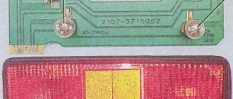
Connection diagram
On the board connector, the tracks leading to the sockets of different lamps are marked with numbers:
- 1 - mass;
- 2 - brake light;
- 3 — side lights;
- 4 — fog lights;
- 5 — reversing lamp;
- 6 — direction indicator.
The paths leading to the sockets of different lamps are marked with certain numbers
Wires for connecting electrical appliances
| Connection type | Section, mm 2 | Insulation color |
| Negative pole of the battery - vehicle ground (body, engine) | 16 | Black |
| Starter positive terminal - battery | 16 | Red |
| Positive contact of the generator - plus battery | 6 | Black |
| Generator - black connector | 6 | Black |
| Terminal on the generator “30” - white block MB | 4 | Pink |
| Starter connector "50" - starter relay | 4 | Red |
| Starter Relay - Black Connector | 4 | Brown |
| Ignition relay on - black connector | 4 | Blue |
| Ignition switch output “50” - blue connector | 4 | Red |
| Ignition switch connector “30” - green connector | 4 | Pink |
| Right headlight connector - ground | 2,5 | Black |
| Left headlight plug - blue connector | 2,5 | Green, gray |
| Generator output "15" - yellow connector | 2,5 | Orange |
| Right headlight connector - ground | 2,5 | Black |
| Left Headlight Connector - White Connector | 2,5 | Green |
| Radiator fan - ground | 2,5 | Black |
| Radiator Fan - Red Connector | 2,5 | Blue |
| Ignition switch output “30/1” - ignition relay | 2,5 | Brown |
| Ignition switch contact “15” - single-pole connector | 2,5 | Blue |
| Right headlight - black connector | 2,5 | Grey |
| Ignition Switch "INT" Connector - Black Connector | 2,5 | Black |
| Six-pin steering column switch - "ground" | 2,5 | Black |
| Double-pole steering column switch - glove box lamp | 1.5 | Black |
| Glove box light - cigarette lighter | 1.5 | Black |
| Cigarette lighter - blue block connector | 1.5 | red blue |
| Heated rear window - White connector | 1.5 | Grey |
Side lights VAZ 2107
The standard dimensions on the VAZ 2107 do not have bright light. Over the years, due to the wear and tear of the glass, even replacing the light bulbs in the headlights no longer helps. Therefore, it is quite logical that the car owner decides to tune the side lights.
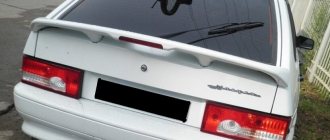
On a VAZ 2107, tuning the dimensions comes down to transferring these lights from the sidelights to a separate lighting element on the body. This way they will be better visible, which will create comfortable and safe conditions for movement on the roads in any weather.
On old VAZs, tuning the side lights is considered a mandatory procedure.
Minor modifications will be required using the following tools:
- electric drill;
- mandrel;
- pliers or pliers;
- Phillips-blade screwdriver;
- side cutters.
Transferring the side lights from the sidelights to the body is impossible without the following materials:
- light bulb socket;
- new sidelights;
- wires for connection;
- terminals;
- new light bulbs (drivers recommend Philips Vision 12 V).
Transfer process
Any tuning requires accuracy and care. And carrying side lights is no exception. Here it is recommended to follow the rule “measure twice, cut once”:
- Measure the diameter of the hole in the car headlight.
- Drill a hole of the same diameter on the new lamp.
- Drilling should be done with drills of different diameters, gradually increasing the diameter so as not to damage the headlight glass.
- Prepare a landing site for the socket with a light bulb (try it on, if the socket does not fit, increase the drilling depth).
- Squeeze the cartridge and insert it into the socket. Using a mandrel, straighten it and fix it securely.
- Insert the light bulb into the socket.
- Connect the wiring to the new lamp and connect the lighting device according to the diagram.
Front lights
The front part of the car usually attracts more attention, so amateurs begin to tune primarily the headlights.
Evil headlights
It’s very easy to give your car a menacing, gloomy and even evil look: just perform tuning like “evil headlights”. This is one of the easiest ways to give the “seven” an unusual appearance.
Depending on the owner’s capabilities, tuning can be done using a variety of materials:
- thin plywood;
- sheet metal;
- tinting film;
- paints.
The car's "angry" squint gives you goosebumps
The essence of this tuning is as follows: cover part of the headlight so that the remaining uncovered headlight resembles evil eyes. If any materials from plywood or metal are selected, then a blank is cut out in advance and glued into the cavity of the headlight. Using film or paint is even easier - just remove the headlight and apply darkening on the inside.
Tuning headlights from plywood painted black
Angel eyes
In tuning, angel eyes are the luminous rings on the “face” of a car - like a BMW. Today everyone can afford this lighting option - it’s inexpensive and fast. In addition, the body of the VAZ 2107 will somewhat resemble an expensive BMW and thereby increase the status of the owner.
Headlights that are very unusual for the “Seven”
There are several technical solutions for making angel eyes with your own hands. The easiest option is to use LEDs. To work you will need:
- white LEDs 5 mm - 2 pcs.;
- 0.25 W resistor;
- wiring;
- transparent rod made of organic glass or plastic (diameter 8–10 mm);
- auxiliary materials (soldering iron, hair dryer, drill and glass jar).
The work is quite painstaking:
- Take the rod and clamp it in a vice.
- Using a drill, drill holes for the LEDs at both ends of the rod.
- Give the rod the shape of a ring - bend it around the jar and heat it with a hairdryer so that the workpiece remains in this shape.
- Solder wires to the LEDs, connect a resistor to one of the wires.
- Assemble an electrical circuit similar to the circuit of lighting devices that is already available on the “seven”.
- Insert the LEDs into the holes of the workpiece and glue them with superglue.
Video: how to make angel eyes
You can buy ready-made angel eyes at a car store - this will make it much easier to connect new lighting fixtures to the standard equipment of the car.
Using LEDs of different shades, you can achieve an even more impressive effect.
What to do if there is no charge, weak charge (battery is discharged)?
If the battery of your VAZ 2107 is discharged, then one of three elements may be “to blame”: the generator, the voltage regulator, and the connections between them. Determining “who is to blame” can be very simple, even without additional devices. How this article will help.
We carry out testing using standard equipment
To monitor the operation of the generator on the “seven” there are two instruments: a voltmeter and a control light on the instrument panel. With their help, you can track the cause of your troubles.
1) Turn on the ignition without turning on the starter
and look at the warning light. It should shine at full intensity, as in the photo. The voltmeter needle, normally, stands on the white part of the scale (photo). Let's say everything is OK - go to point 2 - start the engine.
The battery charge control lamp is on
Position of the voltmeter needle before starting the engine (ignition on)
The lamp does not light, the voltmeter needle remains at zero when the ignition is turned on.
Check fuse No. 10 in the mounting block. 99% of the time it will be burnt out. In this case, all other lamps on the instrument panel will also be de-energized. Replace it with the same one and test again. If the fuse burns out again, you need to look for the cause, that is, a short circuit. We check whether the wires from the generator are disconnected, whether the insulation is frayed somewhere, etc. Diagram 3 at this link will help you find the reason
The lamp does not light up, the voltmeter needle shows normal
We check the wires on the generator to see if the wire has come loose from terminal “61”. If everything is normal there, you need to check whether there is a “plus” on this wire using a test lamp, an indicator screwdriver or a multimeter.
Terminal “61” of the VAZ-2107 generator
If there is a “plus”, we check the “tablet” (aka “chocolate”) and the generator.
There is no “plus” - you will have to remove the instrument panel and check the lamp. Replace the burnt out one. How to remove the panel, watch the video
2) Start the engine
The control lamp should go out, the voltmeter needle goes into the green sector and is located from the middle to the right edge (photo). If everything is so, then most likely the generator is working normally.
The voltmeter shows normal voltage (charging is present)
The lamp remains on or dims slightly
If you give it gas, it goes out at high speeds and lights up again when they decrease. The voltmeter needle is in the white sector and goes to the edge of the green when the speed increases. The generator output is faulty. The same conclusion if the lamp continues to light at any speed, and the voltmeter needle is in the white sector and even goes to red.
Voltage too low (motor running). Weak charge
Read, it may come in handy: If the electric motor of the heater (stove motor) of the VAZ-2107 does not work
Schemes of individual blocks of the seven
Power supply system
Power plant starting system
1 - snack; 2 - relay; 3 — ignition switch; 4 - battery
Ignition system
1 - generator; 2 — ignition switch; 3 - distributor; 4 - switch; 5 — candles; 6 - coil; 7 - battery
Contactless ignition system
External and internal lighting
Windshield wipers and washers
1 — electric motors for windshield wipers; 2 — washing machine motor; 3 — mounting block; 4 — ignition switch; 5 - washing machine switch
Cooling Fan
1 — fan motor; 2 - sensor; 3 — mounting block; 4 - ignition relay; 5 - ignition switch.