Motorcycle IZH Jupiter 5 is one of the latest models of the brand. This model can be found in every corner of our country, working in rural areas and in the city. The popularity of the motorcycle is explained by its simplicity and accessibility. Back in the days of production, even vocational school students could afford it, and today the cost of a running model is comparable to a monthly salary. The motorcycle has a strong frame that can withstand uneven dirt roads; you can easily attach a stroller to it and turn it into a cargo worker. However, not everything is as good as it seems. Jupiter 5 received an outdated 2-cylinder, two-stroke engine. Despite the driving performance, the engine did not have a very long resource and required careful ignition settings. To make life easier for the owners of this model, we will tell you how to set up the ignition on IZ Jupiter 5. In our other review, you can learn about the pros and cons of installing electronic ignition on IZ Jupiter 5.
Caring for a sunrise motorcycle generator - how to remove, what to check and install correctly
Generator maintenance mainly comes down to tightening the threaded fasteners of the generator stator and rotor, as well as the wire terminals.
In order to remove the generator, you must:
- disconnect the wires of the ignition circuit, sensor, brake light and direction indicators from the generator terminals;
- unscrew the three screws securing the stator to the crankcase and remove the stator;
- Unscrew the bolt securing the generator rotor and, with light, careful blows of a wooden hammer on opposite sides of the rotor, remove it from the trunnion and remove the key.
Checking the removed parts
After removing the generator stator and rotor, wash the parts with clean gasoline and carefully inspect them. Disassemble the wire fastening terminals on the stator. Wipe dry all insulating parts of the terminals.
Generator installation
Installation is carried out in the reverse order, in this case it is necessary:
- check the runout of the generator rotor, which should be no more than 0.1 mm with the bolt secured;
- tighten the generator stator without distortions, ensuring a tight fit to all three supports;
- install the ignition correctly;
- The generator wires must be securely fastened and well insulated from each other.
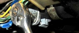
Ignition switch Voskhod - central switch
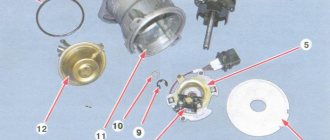
Switch 124005490201 is used as a central software switch that provides the necessary switching of lighting equipment on a motorcycle. The switch has three operating positions >, >, > in accordance with the following operating modes:
- in position > – the generator sensor circuit is shorted to ground, which ensures the engine stops.
- in position > (driving during the day) – the ignition circuit is turned on, the direction indicator circuit operates (when the direction indicator switch is on) and the brake signal circuit (when the brake pedal is pressed);
- in position > (driving at night), two circuits are switched on:
- a) a circuit of speedometer backlight lamps, license plate lighting and city driving (through a throttle, which serves as a device that complements the parametric control of the generator);
- b) headlight lamp circuit A6-32+32 (via the light switch on the steering wheel).
Caring for the central switch comes down to periodically checking the reliability of the switch in the headlight and cleaning the moving and fixed contacts from dust and dirt by washing them in gasoline.
Technical specifications
- Overall length 2,115 mm.
- Overall width 780 mm.
- Overall height 1,025 mm.
- Ground clearance 135 mm.
- Dry weight of the motorcycle is 160 kg.
- Maximum speed 110 km/h.
- Fuel tank capacity 18 l.
- Cruising range on the highway is 160-180 km.
- Fuel consumption on the highway is no more than 4 liters per 100 km.
- Fuel: Gasoline with autol 10-18 in a ratio of 25: 1
- Fordability 300 mm.
- Engine Stroke 58 mm
- Cylinder diameter 61.75 mm
- Number of cylinders 2
- Engine displacement 347 cm3
- Compression ratio 6.8
- Maximum power 18 hp. With.
- Air cooling
- Lubrication system combined with fuel
- Carburetor type K-28ZH
Multi-disc clutch, in an oil bath with an automatic release mechanism. The gearbox is four-speed, two-way. Motor transmission is a rollerless double-row chain, gear ratio - 2.57. Transmission from the gearbox to the rear wheel is a roller chain, gear ratio - 2.33. The frame is tubular and welded. The front fork is a telescopic spring type with hydraulic shock absorbers. Rear suspension pendulum spring with hydraulic shock absorbers Type of brakes drum Type of wheels easily removable, with tangential straight spokes. Tire size 3.25-19″
Step-by-step guide to installing and adjusting the ignition
To carry out the setup, you need to prepare a special tool, a tester, and a light bulb with two wires. A caliper will be needed as a depth gauge. To set the gap it is convenient to use a special feeler gauge.
Setting up SZ on IZ Jupiter 5 consists of the following steps:
- First open the generator cover.
- To make it more convenient to work, remove the right cover from the crankcase.
- Using the generator bolt, turn the crankshaft clockwise. It is necessary to ensure that the breaker contacts open to the maximum distance.
- Unscrew the screw a little and turn the eccentric. It is necessary to set a gap between the contacts equal to 0.4-0.6 mm. After this, tighten the screw well.
- Rotate the crankshaft in the direction of movement of the clock hand. The piston should be installed at TDC.
- You need to turn the crankshaft in the opposite direction, that is, counterclockwise. In this case, the piston should not reach TDC; a distance of approximately 3.0-3.5 mm should remain. By loosening the screws, you should establish the beginning of the contact closure. After this, the screws must be tightened tightly.
- To determine if the contacts are open, use a test light with wires. One wire must be connected to the breaker hammer terminal, and the other to ground. After turning on the ignition, when the contacts are closed, the light should light up.
- If BSZ is installed on IZ Jupiter, then there is no need to set the gap. To determine the moment you need to use a tester. The device should be set to measure voltage. The probes must be connected to the 2nd and 3rd contacts of the DC. While the modulator is not in the DC, the voltage reading on the tester should be 7 V. At the moment when the modulator is in the DC, the voltage reading should be in the range from 7 to 0 V. At this moment, a spark is formed.
- The procedure must be performed on each cylinder. It is advisable to start adjusting the gap on the left breaker. When the left breaker is configured, you can move on to the right one.
Ignition adjustment, but let's start with a little introduction.
If now motorcycles from foreign manufacturers predominate on the roads, then literally 20-30 years ago only domestic Izh “Jupiter” and “Planet” rode on our roads. 2 years difference in production, identical appearance, there are not many differences in them, but still Jupiter-5 wins due to its two-cylinder engine and its easier starting.
Main components:
- Two-stroke, two-cylinder 347.6 engine;
- Air or liquid cooling system;
- Automatic clutch release mechanism;
- Drum brakes;
- 18 wheels;
- The steering wheel has a conventional instrument panel (speedometer, ignition lamp, etc.);
- Two shock absorbers. Setting up the ignition on Izh Jupiter 5 must be done in compliance with all rules. To do this, you need to know the exact algorithm of actions when carrying out this event. Therefore, in this article we will describe in detail how to set the ignition on Izh Jupiter-5.
General information
IZ Jupiter 3 uses (BSZ) 1137.3734, intended for all models equipped with a 12-volt generator. The ignition coil module for Jupiter 4 or another model makes it possible to select the appropriate operating mode of the motor thanks to the serial connection of the output wires.
The device as a whole improves the technical parameters of the vehicle thanks to:
- improved engine starting at low temperatures;
- more stable operation of the power unit, which is achieved as a result of reducing the asynchrony of spark formation, as well as by optimizing the SZ advance angle in accordance with engine speed;
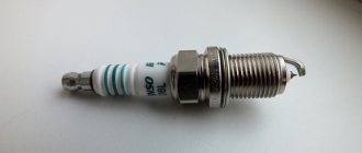
- reducing the level of toxicity of exhaust gases, fuel consumption, as well as reducing deposits on spark plugs;
- stable start of the power unit even on a battery that has run down to 6 volts, provided that certain models of ignition coils are used;
- easier installation and maintenance of the system as a whole.
In what cases is ignition adjustment necessary?
During the operation of the vehicle, the owner faces many problems. The most serious failure is related to the engine. In order to spend significant funds on major repairs, it is necessary to monitor the technical condition of the motorcycle and carry out preventive work, including adjusting the valves and valves (video author - Hana Rulyu).
If you do not monitor the SZ, then the motorcycle engine may not reveal its full potential and will not work at full capacity. This can lead to a reduction in its service life. An ignition adjustment is necessary if the engine is running poorly, the muffler or carburetor is firing. True, before setting up the SZ, you should make sure that the cause of the malfunction is in it.
It happens that the flywheel bolt, which connects the two halves of the crankshaft, comes loose, begins to play and does not work well. Sometimes he even cuts the key.
Setting up the SZ may be necessary after repairing lock 5. The installation and connection itself are carried out according to the diagram.
General information
IZ Jupiter 3 uses (BSZ) 1137.3734, intended for all models equipped with a 12-volt generator. The ignition coil module for Jupiter 4 or another model makes it possible to select the appropriate operating mode of the motor thanks to the serial connection of the output wires.
The device as a whole improves the technical parameters of the vehicle thanks to:
- improved engine starting at low temperatures;
- more stable operation of the power unit, which is achieved as a result of reducing the asynchrony of spark formation, as well as by optimizing the SZ advance angle in accordance with engine speed;
- reducing the level of toxicity of exhaust gases, fuel consumption, as well as reducing deposits on spark plugs;
- stable start of the power unit even on a battery that has run down to 6 volts, provided that certain models of ignition coils are used;
- easier installation and maintenance of the system as a whole.
Electrical circuit diagram of the IZH Planet Sport motorcycle
How to make the transition to contactless SZ? When the engine is switched off, the indicator lights up, and when the engine is running, it goes out.
How can I modify the generator? After long-term use, the ignition circuit of IZ Jupiter 5 is changed by the owners to systems from other Soviet motorcycles.
The turn signal switch is located on the frame under the gas tank.
Wiring diagram for IZH Jupiter 5 The bike of the fifth Jupiter has a contact SZ, which is battery-powered, so the operation of the vehicle is highly dependent on the state of charge of the battery. Install the generator in reverse order.
Burnt contacts, oily spark plugs and batteries with a charge of less than 12 V further worsen sparking. An additional coil is used as an exciter. Charging IZH
Related article: Checking the loop resistance phase zero
How to correctly set the ignition on Jupiter 5
Home » Articles » Automotive articles » How to correctly set the ignition on Jupiter 5 Today, the Jupiter 5 motorcycle model is one of the latest in this brand and is still popular. This is due to the affordable price and ease of technical setup. But unfortunately, the model has a drawback - a two-cylinder engine with a short resource, which requires ignition adjustment. How to set the ignition to Jupiter 5 will be discussed in the article.
Contactless ignition
- We unscrew the candles. There is no need to remove them from the caps. You just need to lean them on the ribs of the cylinder.
- Now you need to catch the crankshaft at the dead point of one piston. It should be rotated back so that the piston drops 2.6 mm.
- In this case, the modulator must be in free rotation. Due to this, with the ignition in the “on” position, the moment of spark formation is “caught”.
- And after that, the resulting position is fixed by pulling the modulator.
- We carry out all the manipulations from steps 1 to 3 with the second cylinder. After setting it to 2.6 mm, you need to rotate the crankshaft by the generator nut.
If a coincidence occurs, then everything was done correctly. If not, then proceed as follows:
- late ignition - loosen the control modulator nut and act according to scheme 1–3;
- early ignition - grind the modulating edge until the desired effect is obtained (until the spark on the spark plug appears at the right time).
Contact ignition
How to set contact ignition on Jupiter? Some of the models left the factory with contact ignition. To set it up, you need to prepare: screwdrivers, a 12V light bulb with two wires coming from it, a caliper, a spanner and an open-end wrench.
- First you need to remove the cover. This will open access to the ignition mechanism.
- Then unscrew all the spark plugs and place them in the cylinder located on the right; insert a screwdriver instead of one.
- Now you need to turn the nut (located in the center) connected to the crankshaft. The piston is placed in m.t. (above). M.t. is at the maximum protrusion of the screwdriver (the position is fixed with a mark).
- The next step will require help. It is necessary that one person holds the screwdriver, and the other on the m.t. Using a caliper, I noted the coincidence of the instrument scale with the mark.
- Now we ask an assistant to turn the crankshaft counterclockwise.
On the body of the caliper we mark the lowering of the screwdriver at 2.6 mm. This is how the advance is adjusted.
When aligning the piston, pay attention to the ignition cams (which one is open). The lamp contacts are applied to it: to ground and to the cam. Release the fixing screw and begin to rotate the adjusting screw. As soon as the lamp goes out, the moment is caught. At this stage, the adjusting screw is held, and then it is tightened with a fixing screw
The setting of the first cylinder is completed. Proceed to the second according to a similar scheme
At this stage, the adjusting screw is held, and then it is tightened with a fixing screw. The setting of the first cylinder is completed. Proceed to the second one using a similar scheme.
Conclusion
It is possible to set the ignition correctly on Jupiter 5, but this motorcycle, despite its simplicity, is a rather demanding mechanism. A lot depends on the ignition setting: speed range, engine power and fuel consumption. Knowing how to set up contact and non-contact ignition, you can always stay on top. And for those who do not have enough instructions, we invite you to familiarize yourself with the material: how to set the ignition on Jupiter video.
Contactless ignition on Izh - understanding unclear terms
- BSZ
- contactless ignition system; - Modulator
- metal disk (steel 0.8-1.0 mm thick), plate, curtain. Installed on the axis of the ignition timing mechanism (distributor shaft). Produces “generation” of magnetic pulses to the Hall sensor. - Switch
- an electronic device that supplies electrical impulses to the ignition coil; - A Hall sensor
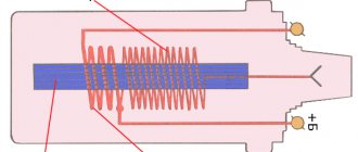
is a device capable of detecting the presence or absence of a magnetic field. If there is a field, a control pulse goes to the switch. The sensor position is fixed. - The ignition coil
is a converter of pulses coming from the switch into high-voltage pulses supplied directly to the spark plugs.
Final actions
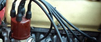
You should put rubber caps on the armor wires, and insert the latter into the candlesticks or coil above. If you skip this step, the motorcycle will stall when riding in rainy weather, as moisture will get into the battery.
By inserting spark plugs into the tip, it will be possible to maintain excellent contact between the battery and the volume of the vehicle. Now you will need a pre-purchased set of wires. The switch, coil and hall sensor are connected by wiring. She needs to be isolated. Of the entire mass, only a common plus is required.
System assembly and installation
The contacts in the breaker, the capacitor, the ignition bobbins and the armor wires, which are part of the previous ignition device, are probably eliminated. The switch should be installed in the glove compartment on the right, and the ignition coil directly under the tank. There are no gaps for fastening on the reel, which means it can be attached using a thick layer of adhesive tape. The standard bolt is also eliminated along with other parts.
In place of the bolt, install a pin of the specified size and put on a washer. Then, the rotor is tightened with a nut located at its end. The hall sensor is attached to the stator by any means. The basic rule when installing it is to set the optimal cross-sectional distance of the modulator and the ratio of the radius and line of symmetry.
When the hall sensor can be secured, we apply the modulator. It should fit into the hole made in the sensor. In most situations, there is a discrepancy between the sizes, so it is necessary to place washers on the stud. If you manage to maintain the required gap, it is recommended to install an engraver and tighten the modulator with a third-party nut.
Required Parts
In order for the ignition system to work correctly, a number of auxiliary parts are required. They are listed below:
- Switch for BSZ VAZ cars. You should not choose exclusively from the low price segment. The Astro switch has a lot of positive reviews;
- Hall Sensor. The best option for Jupiter 5 is a similar manufacturer VAZ. By purchasing it in branded packaging, you protect yourself from counterfeits;
- Ignition coil with two terminals. You should choose between the gazelle engine number 406 or Oka with an electronic ignition system;
- A pair of silicone armor wires with rubber caps;
- The modulator is a butterfly-shaped plate made of iron.
Modulator
The most difficult stage is the production of the modulator. It is important to maintain the required shape. The more accurately the required dimensions are observed, the lower the likelihood of problems occurring after the system is implemented, that is, there will be no need to adjust it with a file. The ignition timing must match on any cylinder used.
The bolt hole must be located in the middle. Otherwise, the engine operation will not be synchronized. It is also recommended to check the integrity of the crankshaft bearings. If you find defects, you should immediately replace it.
The contact ignition is not able to work normally if the bearings are damaged. The thickness of the part should not exceed one and a half millimeters. If it is thin, it will not be possible to avoid deformation, and if it is thick, it will come into contact with the surface of the hall sensor housing.
To create the plate, it is allowed to use any material except steel. Aluminum and others should not be used as they are not magnetic. The drawing that must be followed can be found in the public domain. The presented diagram will be useful to those people who decide to modernize the vehicle ignition device. Below are methods for installing electrical ignition devices in Jupiter. It must be turned by a professional turner. He will make a simple disk and draw on it the markings of elementary distances between the corners. Then, in accordance with it, you will cut out the necessary sectors at home. The cost of the modulator is seventy rubles.
It is not advisable to use an ordinary plate, since its width is less than twelve millimeters. This will not be enough to fully accumulate the energy resource in the coil. Of course, it can be installed, but achieving four thousand revolutions per minute will become impossible.
In addition to the above you will need:
- A stud with an applied thread of seven millimeters, pitch 1, as well as a pair of nuts with washers of the corresponding parameters.
The priority material for these components is brass. This is explained by the least magnetization of the plate from the generator rotor. If you use a standard bolt, then difficulties may arise with the implementation of the ignition. The bolt tends to follow the modulator as it is tightened. However, it is necessary to observe the leading indicator, maintain the same position of the rotor and modulator, and tighten the bolt. It is advisable to use a pin, since many are not able to perform all the necessary actions in total; - A set of wires with connectors for ignition without contact from VAZ. This part can be purchased or made with your own hands.
Generator
The motorcycle is equipped with a 3-phase alternator, which has an electromagnetic excitation circuit. The principle of its operation is based on some features. So, the electrical circuit of “IZH Planet-4” looks like this: the current is supplied to the rectifier, which, in turn, converts it into direct current, then supplies it to consumers. The factory instructions for the generator contain the following elements:
Voltage regulator with rectifier “BPV-14-10”;
The head light circuit consists of the rear brake light, parking light and color control light. The motorcycle is equipped with a speedometer with mileage indicators (daily and total), a tachometer, indicator lamps for turn signals and head lights, a voltmeter and an engine temperature sensor. Very often during operation it is necessary to adjust the gap between the contacts of the breaker. To do this, it is best to use a diagram and special tools to know which elements need to be dismantled.
While easily fixing mechanical failures, motorcyclists experience difficulties if the electrics fail. It’s completely in vain, the wiring diagram of the planet Izh 5 is not complicated, it’s easy to figure out.
There is no need to have special stands and equipment for repairs. A minimum knowledge of electrical engineering and a simple avometer (tester) is enough; even often you can get by with just a test lamp.
We will tell you in more detail about the main electrical wiring components and possible malfunctions. The Izh Planet wiring diagram makes it easy to find a broken wire or damaged insulation (for example, a bad contact always gets hot).
In this case, we look to see if there is a spark at the coil output and at the output at the spark plug contact. Let's take a closer look at the main wiring components of the Izh Planet.
Setting up contact ignition on Izh Jupiter - 5
Let's take a step-by-step look at how to set up contact ignition on this device:
- Align the piston of the desired cylinder: - insert a screwdriver into the cylinder - rotate the crankshaft while holding the screwdriver
- Take a ruler and place it next to the screwdriver.
- Rotate the crankshaft, holding the screwdriver down with your finger so that it is level. We find a dead point.
- Turn the crankshaft in the opposite direction (1.5-2 mm).
- A spark is generated when the cam opens, locate the two adjusting bolts.
- Take a light bulb with two contacts, connect one to ground, the other to the contact.
- Turn on the ignition switch.
- You need to find the moment when the light comes on (the moment it lights up, the start occurs), and when it goes out, the contact closes on the contrary.
- Turn off the ignition, do and adjust the same with the second cylinder
Fuel level
Adjusting the K-65 carburetor begins with measuring the amount of gasoline in the tank of the float section. To do this, you will need to prepare a certain list of tools. Almost every home craftsman has them. The tool will be required during the process of dismantling the carburetor.
When the device is removed from the slots, you will need to remove the cover from it. It covers the float chamber. Next you need to take a ruler. The float has a special tongue. It needs to be unbent and bent to make adjustments. Due to this, the fuel level in the chamber will change.
You will need to place a ruler on the connector plane. Next, the tongue must be adjusted correctly. The strip on the float should be at 13 mm. The deviation is ±1.5 mm. The floats themselves must be level. The adjustment must be made very precisely. The operation of the carburetor depends on this.
Main stage
As noted in the assembly diagram of the Izh-Planet 5 box, further disassembly operations are carried out above the insides of the roof of the unit, since the secondary shaft and sector could remain in it. If it is necessary to remove them, you need to straighten the petals of the lock washer, unscrew the nut, remove the star and washer. Holding the gear very carefully to prevent the shaft from jumping out, the cover is moved to a clean and flat surface with the gear facing up.
It is worth noting that the bearing of this part of the assembly does not have a retaining ring. Therefore, when removing the shaft with bearing, the rollers may fall out, so be careful. If the specified element has exhausted a decent service life, there is a risk that when dismantling the secondary shaft, the outer ring may jump out of the seat and remain on the rollers. Next you need to start pressing out the oil seal. To do this, the installation rings are removed from the hole in the cover, after which the outer ring of the bearing is removed.
General recommendations
The carburetor must be in good working order. If there is any abnormality in its system operation, it is necessary to carry out system maintenance.
If necessary, the system will need to be thoroughly cleaned. All consumables are replaced with new seals. The air filter must be clean. If necessary, it must be washed. In some cases it will need to be completely replaced.
When adjusting the carburetor, the engine must be warm. To do this, you can drive several kilometers along the highway. Only after this can you begin the procedure described below.