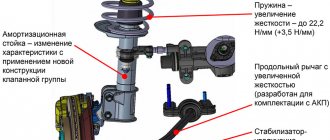
Not long ago, a standard problem with VUT appeared - air is being cut and because of this the engine is unstable. I decided to change the VUT, but then a problem arose, one of the studs securing the GTZ was torn off, not torn off, but rather the thread was torn off, in the end I decided not to install a stock part, but to install something more retarding.
This story was very long and a lot of problems arose, but in the end we acquired: Pedal assembly from a 2013 Priora. some kind of super-mega-new model - 1300 rubles (pedal + VUT + GTZ + 2 pieces of fittings per ABS block) VUT Priora/Kalina - 2000 rubles GTZ 21214-3505010-03 - 1400 rubles GTZ tank round from shnivy - 100 rubles Brake fluid 1l - 100 rubles
In general, the set of VUT Priora + GTZ 21214 + pedal bracket fits almost perfectly, except for the unknown brake light switch...
Your advantages when purchasing at Autocompas.ru
- Huge selection of auto parts and low prices;
- Fast delivery, usually within 24 hours;
- Warranty and right of return;
- Emphasis on proven and branded manufacturers of all price segments;
- Safe and convenient online purchase with many payment options;
- Qualified support and advice + recommendations from experts when choosing and purchasing.
Range of auto parts in stock and on order
A wide variety of manufacturers and high-quality auto parts guarantee the mobility of your car and safety on the roads. A huge assortment is constantly available from stock online. Certified and reliable aftermarket suppliers, dealers, and regional market participants provide a full range of auto parts at reasonable prices. Our knowledgeable support staff is always available to assist you in your search.
Quality of service in our online store
The service and online offers from Autocompas.ru have already won several awards and made us a leader in the Russian market in the field of sales of auto parts for foreign cars, 40+ thousand people visit the site every day and many of them become our regular customers. Satisfied customers are our goal. Rely on Autocompas.ru as a reliable supplier of auto parts.
29.11.2019
A review section has been introduced on the site, using the latest technologies, now each client can write a review from their personal account.
01.01.2019
A completely new and intuitive returns system.
23.05.2018
Global update of the “Delivery” section! Track numbers in your personal account and convenient cargo tracking.
Removal and installation of GTZ on Priora
The first step is to pump out the brake fluid from the reservoir using a syringe and flexible tube. Then we disconnect the power connector chip from the tank cap, or unscrew it entirely.
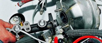
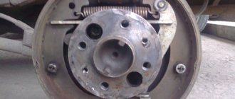
After this, unscrew the two brake pipes on the right side of the GTZ, as shown in the photo below.
The best option is to use a special split wrench designed for unscrewing brake pipes and hoses. The result of the work done is presented below.
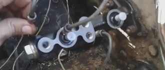
If there is liquid left in the tank, you need to place a container or a dry cloth to drain the remaining liquid. Then we take the head with the ratchet and unscrew the two nuts securing the master cylinder to the vacuum booster.
One is higher and the second is lower. As a result, it is possible to remove the GTZ without any problems.
If it is necessary to replace the cylinder with a new one, we buy the part and install it in the reverse order. It is worth noting that when adding brake fluid to the reservoir, air may enter the system. If this happens, it is necessary to bleed the brake system through special fittings in the cylinders.
The price of a new GTZ for Priora is from 1,500 rubles for the original. It is worth noting that you can buy a high-quality spare part from a car disassembly for half the price of a new one.
Master brake cylinder VAZ 2170 Priora
- Repair manuals
- Repair manual for VAZ 2170 (Priora) 2004+.
- Master brake cylinder
9.6.1 Master brake cylinder Removal and installation of the master brake cylinder reservoir Removal and installation of the master brake cylinder
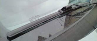
9.6.2 Removal and installation of the master brake cylinder reservoir The reservoir is removed for replacement or preventative flushing. In addition, sometimes it becomes necessary to remove the tank to replace the rubber bushings that secure it. You will need: a 10mm wrench, flat and Phillips blade screwdrivers. 1. Remove the windshield frame trim (see “Removal and installation…
9.6.3 Removing and installing the main brake cylinder You will need: “10”, “13” wrenches, flat-blade and Phillips-blade screwdrivers... ...as well as a special “13” wrench for unscrewing the brake pipes. 1. Remove the windshield frame linings (see “Removing and installing the windshield frame linings”). 2. Remove the soundproofing...
↓ Comments ↓
1. Car structure
1.0 Car structure 1.1 General information about the car 1.2 Passport data 1.3 Car keys 1.4. Controls 1.5. Heating and ventilation of the cabin 1.6 Ensuring a comfortable air temperature in the cabin 1.7. Doors 1.8. Passive safety equipment on the car 1.9. Seats
2. Recommendations for use
2.0 Recommendations for use 2.1. Safety rules and recommendations 2.2 Running in the car 2.3 Operating the car during the warranty period 2.4. Preparing the car for departure
3. Problems along the way
3.0 Malfunctions along the way 3.1. The engine does not start 3.2 Malfunctions of the fuel injection system 3.3 Idle speed has disappeared 3.4. Interruptions in the operation of the 3.5 engine. The car moves jerkily 3.6 The car accelerates poorly 3.7 The engine stalled while driving 3.8. Oil pressure dropped to 3.9. Engine overheating 3.10. The battery does not recharge 3.13. Knocks in the engine 3.16. Wheel puncture
4. Maintenance
4.0 Maintenance 4.1. General provisions 4.2. Inspection work 4.3. Lubrication and filling works 4.4. Diagnostic work 4.5. Repair and adjustment work
5. Engine
5.0 Engine 5.1 Design features 5.2 Possible engine malfunctions, their causes and solutions 5.3 Useful tips 5.4 Checking compression in the cylinders 5.5 Removing and installing the decorative engine casing 5.6 Removing and installing the engine splash guard 5.7 Installing the piston of the first cylinder to the TDC position of the compression stroke 5.8 Replacing the drive belt gas distribution mechanism and tension roller 5.9 Replacing the power unit supports 5.11. Replacing engine seals 5.13. Engine cylinder head 5.15. Engine repair 5.16. Lubrication system 5.17. Cooling system 5.18. Power supply system 5.19. Design Features
6. Transmission
6.0 Transmission 6.1. Clutch 6.2. Gearbox 6.3. Front wheel drives
7. Chassis
7.0 Chassis 7.1. Front suspension 7.2. Rear suspension
8. Steering
8.0 Steering 8.1 Design features 8.2 Possible steering malfunctions, their causes and solutions 8.3. Steering column 8.4. Steering linkage 8.5. Steering gear
9. Brake system
9.0 Brake system 9.1 Design features 9.2 Possible malfunctions of the brake system, their causes and solutions 9.3 Bleeding the brake system hydraulic drive 9.4 Removing and installing the vacuum brake booster 9.5 Replacing the brake pedal axle bushings 9.6. Main brake cylinder 9.7. Front wheel brakes 9.8. Braking mechanisms of the rear wheels 9.9. Pressure regulator 9.10. Brake hoses and tubes 9.11. Parking brake
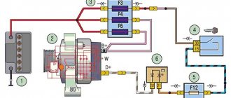
10. Electrical equipment
10.0 Electrical equipment 10.1 Design features 10.2. Battery 10.3. Mounting block (relays and fuses) 10.4. Generator 10.5. Starter 10.6. Ignition switch (lock) 10.7. Electronic engine control system (ECM) 10.8. Ignition system 10.9. Lighting, light and sound signaling 10.10. Windshield cleaner 10.11. Washer reservoir 10.12. Electric fan of the engine cooling system 10.13. Electric motor of the heating and ventilation system fan 10.15. Cigarette lighter 10.16. Instrument cluster 10.18. Electronic anti-theft remote control system 10.19. Immobilizer 10.21. Replacing sensors and switches
11. Body
11.0 Body 11.1 Design features 11.2 Possible body malfunctions, their causes and solutions 11.3 Removing and installing windshield frame lining 11.4 Removing and installing soundproofing upholstery in the engine compartment 11.5. Removing and installing bumpers 11.6 Removing and installing the fender liner and protective wing cover 11.7 Removing and installing the front fender 11.8 Removing and installing decorative sill trims 11.9. Hood 11.10. Trunk lid 11.11. Doors 11.12. Seats 11.13. Seat belts 11.14. Rear view mirrors 11.15. Interior fittings 11.16. Instrument panel 11.17. Heater 11.20. Body care
12. Applications
12.0 Appendix 12.1 Appendix 1. Tightening torques of threaded connections, Nm 12.2 Appendix 2. Fuels, lubricants and operating fluids 12.3 Appendix 3. Nominal filling volumes 12.4 Appendix 4. Basic data for adjustments and monitoring 12.5 Appendix 5. Spark plugs used on vehicles 12.6 Appendix 6. Lamps used on a car 12.7 Appendix 7. What you need to have in a car 12.8 Appendix 8. Tools used when repairing a car
13. Electrical diagrams
13.0 Electrical Diagrams 13.1 Diagram 1. Instrument Panel Harness Connections 13.2 Diagram 2. Vehicle Front Wire Harness Connections 13.3 Diagram 3. Engine Electronic Control System (ECM) Harness Connections 13.4 Diagram 4. Vehicle Rear Wire Harness Connections 13.5 Diagram 5. Light Harness Connections license plate light 13.6 Diagram 6. Left front door wiring harness connections 13.7 Diagram 7. Right front door wiring harness connections 13.8 Diagram 8. Rear door wiring harness connections
Description of the VAZ 2170 hydraulic brake drive system
The design of the system is based on a dual-circuit circuit with diagonal distribution. That is, one circuit combines the drive mechanisms of the right front wheel and the rear left wheel, the second - the left front and rear right wheels. If one of the circuits fails, the second will be activated, which will ensure an effective shutdown.
The brake drive circuit consists of:
- brake mechanisms;
- master brake cylinder;
- vacuum booster;
- pipelines;
- tank GTZ;
- pressure regulator;
- brake pedal.
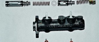
A cylinder with a two-section fluid reservoir is attached to the amplifier cover. It itself has two pistons arranged in series. During operation, the pistons wear out and cannot be repaired - only replaced.
Description of design
The service brake system is hydraulic, dual-circuit, with diagonally separated circuits. In normal mode, when the system is working properly, both circuits operate. If one of the circuits fails (depressurizes), the other circuit provides braking to the vehicle, although with less efficiency.
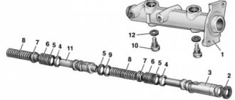
Elements of the brake system : 1 — front wheel brake disc; 2 — front wheel brake tube; 3 — front wheel brake hose; 4 — hydraulic drive reservoir; 5 — main brake cylinder; 6 — vacuum booster; 7 — brake pedal; 8 — rear wheel brake tube; 9 — pressure regulator; 10 — rear wheel brake mechanism; 11 — rear wheel brake hose; 12 - floating bracket
The service brake system includes wheel brakes, a pedal assembly, a vacuum booster, a master cylinder, a hydraulic reservoir, a pressure regulator in the rear wheel brakes, as well as connecting tubes and hoses.
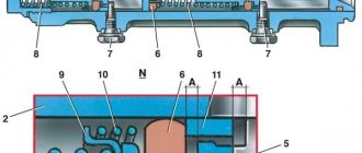
The brake pedal is a suspended type. A brake signal switch is installed in the pedal bracket - its contacts close when the brake pedal is pressed. Pedal assembly with vacuum booster and main brake cylinder : 1 - brake pedal;
2 — brake pedal bracket; 3 - vacuum booster; 4 — hydraulic drive reservoir; 5 - main brake cylinder The vacuum brake booster is located between the brake pedal and the main brake cylinder and is attached with two nuts to the brake pedal bracket, which, in turn, is attached to the body. The vacuum amplifier is non-separable; if it fails, it is replaced with a new one. The brake master cylinder is attached to the vacuum booster housing with two studs. On top of the cylinder there is a reservoir for the hydraulic drive of the brake system, which contains a supply of fluid. There are markings for the maximum and minimum liquid levels on the tank body, and a liquid level sensor is installed in the tank lid, which, when the liquid level drops below o, turns on the alarm in the instrument cluster. When you press the brake pedal, the pistons of the master cylinder move, creating pressure in the hydraulic drive, which is supplied through tubes and hoses to the working cylinders of the wheel brake mechanisms.
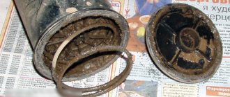
Main signs of GTZ breakdowns
Lada
LadaThe main task of this unit is to uniformly distribute the working fluid of the hydraulic system along the contours. Therefore, the slightest imbalance leads to a decrease in braking efficiency. To determine the condition of the master cylinder or the need to replace it, experts advise paying attention to factors such as:
- readings of the warning lamp on the dashboard;
- brake oil leaks;
- cracks on the body
If at least one of these signs is detected, repairs should be started immediately. It is possible, of course, to partially restore defective parts, but practice shows that it would be more rational to install a new assembly.
Brake master cylinder device
The braking system of a car today is a complex system of mechanical and electronic components and parts that are designed to slow down or stop the vehicle. Brakes are our safety, so timely maintenance and repair of the brake system is a priority concept by default.
The main link in the braking system is the master cylinder.
Repairing a master cylinder naturally requires knowledge of its structure. As the main mechanism that powers the brakes, the brake master cylinder is essentially simple. Like everything ingenious.
Its main components are: pistons that operate the front and rear brake circuits, return springs and O-rings. The main brake cylinder works in tandem with a vacuum booster.
Before you begin repairing the brake cylinder, you need to know that the primary and secondary piston assemblies are not disassembled, but replaced with new ones.