1200 rub. for the photo report
We pay for photo reports on car repairs. Earnings from 10,000 rubles/month.
Write:
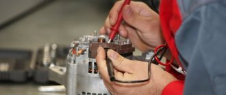
Those who are engaged in repairing a car generator cannot do without the procedure for checking the regulator relay. How to check the VAZ regulator relay, watch the video lesson.
And so there is a relay regulator 3613702 which is installed on Samara (VAZ 2108, 2109) and to check it you need a power source with a voltage of about 16 V and a light bulb, and all data will be taken with a multimeter. When applying voltage, we monitor the light bulb (incandescence) in the region of 14 V; it should go out if the relay is working properly.
Today we will tell you how to check the VAZ 2109 generator voltage regulator relay. In the early 90s, the VAZ automobile concern released the 2109 model car. As in any mechanism, the health of the car is ensured by the VAZ 2109 generator voltage regulator relay as one of the main components of the electrical system. Most of the machine functions depend on constant current power.
In the Zhiguli 2109, as in many other cars of modern brands, on-board computers are used to synchronize the operation of the equipment and for its correct operation. Motorists call them the “brain” of the car. And for a computer to operate, a constant current must be maintained in the electrical network. This is impossible if the VAZ voltage regulator fails.
Generator operating principle
The VAZ-2109 generator consists of an armature, two covers, a stator, a pulley with a fan. These are the main elements of the body. There are windings on the stator and rotor. The first consists of three parts, since it is necessary to obtain a three-phase voltage at the output. There is only one reason for this - such a scheme allows you to get rid of pulsations, therefore, the efficiency of the device is higher. But this also imposes some requirements, which will be discussed below.
The operating principle is based on the fact that the rotor moves inside the stator winding. It has a coil that is powered by the vehicle's on-board power supply. Consequently, a constant magnetic field is formed around the rotor, which also moves. And these are the main conditions for the operation of the generator set. The only thing that should be ensured for normal operation is voltage stabilization on the generator rotor winding.
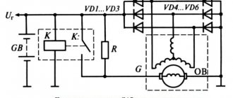
Connection diagram and operating principle
The voltage regulator on most cars is connected to the on-board network according to the diagram below.
The operating principle of a voltage regulator (VR) is the same as that of a relay. In other words, it opens and closes an electrical circuit. That is why the device is also called a relay regulator. It is triggered when a predetermined voltage value coming from the generator changes.
The first regulators had an electromagnetic design. These were real relays. Modern devices are made on the basis of semiconductors. They are small in size, and in addition, they work much more accurately and efficiently. Some of them are even equipped with special alarms that allow the driver to monitor their performance.
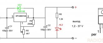
How to increase on-board voltage
Where and how is a diode placed in the LV circuit on the generator in order to increase the voltage in the car network and better charge the battery? Here I propose a simple solution, raising the on-board voltage, without going anywhere in the car and its circuits.
I searched in my archives and did not find the material from which I read this decision. “Structurally, voltage regulators have an upper limit of 13.6V. This is due to the “old” connection diagram, from which the new one was copied and “successfully improved”. In it, the necessary voltage from the on-board network, supplied to the regulator for comparison, passed through a chain of wires. On them it dropped to normal. According to the new scheme, we have a chronic undercharge of the battery. Which, with the arrival of winter, makes starting the engine in the cold quite problematic. But if you install a pre-heater, starting the engine will be much easier.
It should also be noted that the battery begins to absorb energy (charge) only when its temperature is above zero. Therefore, in winter, if you make short runs and the battery does not have time to warm up under the hood to at least zero (plus charging time), it will be constantly discharged. And soon it will die... It is believed that after starting the engine, in order for the battery to recover, you need to drive for at least 20 minutes. Just go, and not stand in traffic jams! How to increase the voltage in the network?
Very simple! It is necessary to make the regulator “think” that we have low voltage in the network. Thus, the generator will give us the missing volts. A diode will help us do this. In a generator with a built-in voltage regulator, you need to place a diode in the circuit, as shown in the figure.
Diode bridge
It is necessary to ring each diode separately in different directions. But normally the signal will sound only once. If a squeak is heard in both cases, the part needs to be replaced. However, in fact, the easiest way is to install a completely new bridge - it is not that expensive.
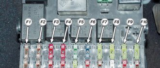
VAZ 2109 carburetor charging relay where is it located
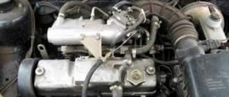
This article tells you how to check with your own hands the generator installed on a VAZ-2109 car.
It is worth noting that it makes no difference which engine is installed on the car - an injector or a carburetor. In both cases, diagnosis is made using the same algorithm.
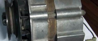
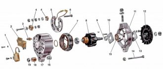
Dismantling the generator
First of all, you need to disconnect the battery to completely cut off the power to the car.
- disconnect all wires from the generator;
- loosen the nuts holding it in place;
- lift the device and remove the belt;
- completely unscrew the screws of the fixing bar from the cylinder block;
- under the engine there are bolts securing the bracket - they need to be removed;
- the generator is removed.
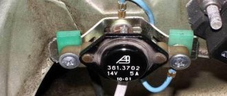
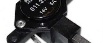
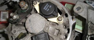
Relay regulator VAZ 2109:
1 – brush holder, 2 – brushes, 3 – voltage regulator
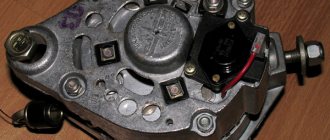
Diagnostics of the VAZ 2109 generator regulator relay
Check the serviceability of the VAZ 2109 voltage regulator. Connect a 12 V test lamp to the brushes. Apply 12 V voltage: “ ” to the terminal, and “–” to the “ground” of the brush holder. The indicator lamp should light up
DIY three-level voltage regulator for VAZ
Even a fairly powerful generator of a VAZ 2110 car these days does not always cope with the ever-increasing number of electricity consumers, which leads to situations when its output voltage drops below a critical value (when the battery stops charging). However, this problem has its own solution and the best option is to install a three-level voltage regulator.
Manufacturing of a three-level voltage regulator on a standard basis
To implement this task we will need:
- Two 25CTQ045 assemblies (with diodes using the Schottky barrier effect), providing a voltage drop of up to 0.4V. Such assemblies can withstand a current of 30A, but if you come across less powerful ones, you can install them (a 5A rating is quite enough). Alternatively, you can use MBR1545 diodes;
- Radiators for cooling diodes;
- Three-position toggle switch with middle position parameters 125V/6A for direct current and 250V/3A for alternating current;
- A plastic case of a suitable size (the case from the central locking unit will do);
- Fastening for the device body (you can use the mounting bracket for the electric door lock);
- two pieces of wire of different colors with a diameter that allows you to pull them through the slot in the generator cover (in our case, red and black);
- plastic retainer for holding wires in the regulator body.
The diode connection diagram looks like this:
In this case, when switch S1 is set to position “1”, the generator is operated in normal mode - the diodes are excluded from operation.
Setting the S1 toggle switch to position “3” ensures the connection of one diode, as a result of which the output voltage of the generator increases by 0.3-0.4V.
Moving the switch to position “2” activates two Schottky diodes (connected in series), and accordingly the voltage will increase by 0.6-0.8V.
The approximate location of the circuit parts in the case is shown in the photo below (we connect the red wire to the “input” and the black wire to the “output”).
To ensure the connection of our homemade diode device to the generator, we supply the red wire with a male terminal (we will connect it to the female wire coming from the diode bridge). In turn, we supplement the black wire with a “female” type contact and connect it to the excitation terminal of the voltage regulator. As mentioned above, we pull the wires through the gap in the plastic cover of the generator.
At the last stage of installation, we fix the device body in any convenient place (away from strong heat sources).
Installing a factory-made three-level voltage regulator
For those car enthusiasts who are not too confident in their abilities and are not financially constrained, there is an easier and faster way to deal with voltage sags, namely installing a three-level voltage regulator purchased in a store. To perform such work, you do not need special technical skills, but you just need to purchase a regulator and prepare a minimum set of tools in the form of a “10” key, a Phillips screwdriver, a knife and a device for crimping contacts.
Installation of a three-level voltage regulator is performed in the following sequence:
- To avoid problems, disconnect the corresponding power wire from the negative terminal of the battery;
- Using a “10” wrench, unscrew the M6 nut on the generator and move the wires aside;
- We disconnect the block with wires from the generator and, pressing the latches, remove the protective casing from it;
- Unscrew the screws securing the voltage regulator and disconnect it;
- In place of the old regulator, we install the brush holder of the new device (the outgoing wire, for reliability, can be additionally reinforced with sealant);
- We stretch the harness going from the brush holder to the body of the three-position regulator along the standard wiring, fixing it with plastic clamps;
- We fix the regulator body in any convenient place, not forgetting to ensure the presence of a reliable “ground” (even to the point of extending an additional shunt wire connecting the regulator to the generator body).
Examination
In order to determine the nature of the breakdown at home, you first need to know how to diagnose the generator.
The first stage is carried out without removing the device from the machine. There are several options, but the best quality is a multimeter. True, for this it is best to involve someone you know.
First of all, you need to find out whether the voltage regulator is capable of doing its job. Experts note that most often it is because of this that the generator may not function properly. The problem with it arises due to excessive voltage in the electrical network.
The generator itself is tested like this:
- set the multimeter to volts;
- start the power unit;
- measure the voltage at the battery and at the generator terminals.
Normally, the device will show from 14 to 14.2 volts. After this, you will need to depress the gas pedal - the voltage increase should not exceed half a volt in this case.
An increase in this indicator indicates that the generator’s performance is impaired. Most likely, the voltage relay will need to be replaced.
Alternatively, you can also do this:
- start the engine and let it run for a while;
- press the gas and bring the crankshaft to 3 thousand revolutions;
- turn on the headlights (high beam);
- heated rear window;
- stove fan.
With such a load, the battery voltage should be more than:
- 13.2 volts (generator type – 9402.3701);
- 13,6 (37.3701).
Indicators different from normative ones indicate:
- winding faults;
- failure of the voltage regulator;
- brush breakage.
To exclude the regulator from the list, you need to de-energize all devices except the headlights and measure the voltage again. If the specified node is serviceable, then the indicators will be as follows:
- for 37.3701 – up to 14.6;
- for 9402.3701 – up to 14.7.
This is interesting: Which winter tires are better and how to meet the season fully armed?
Characteristics of the voltage regulator
What is a DC regulator, what role does it play in a car alternator, what voltage should the alternator produce? Is it possible to raise and increase the number of output parameters using a simple three-level device? First, let's look at what the design of the element is and what its purpose is.
Purpose
So, what is an electronic car generator voltage regulator used for? When starting a power unit, as is known, the crankshaft begins to rotate first; this occurs as a result of the influence of direct current on it. The current in amperes initiates the movement of the rotor mechanism, after which the generator unit begins to function. A constant voltage regulator is used to control all processes.
If the voltage is not high, and due to the failure of the generator voltage regulator there is no power to the mechanism, the unit will not be able to start. If there is no generator power, the current in amperes will simply not be supplied to the equipment. A simple voltage regulator makes it possible to keep the current in amperes in the specified range; this is its main purpose.
Design
Now let’s look at the issue of the device: any increasing pH, even simple and homemade, will consist of:
- Rectifier block. This element includes several diode components, usually their number is six. All components of this block are connected to each other via a special bridge.
- Rotary mechanism with winding. This device rotates around an axis; its purpose is to generate a magnetic field inside the unit.
- Stator mechanism. On the body of this device there are three windings connected to each other. Thanks to these windings, it is possible not only to provide a higher charge, but also to increase power for the car battery. They also make it possible to supply current to the entire electrical network of the vehicle.
- Impellers. This element is installed on the outer part of the mechanism. The impeller is used to blow and cool the winding; without it, the latter may overheat.
- Case cover. Its purpose is to hide all the constituent structural parts of the unit, thereby ensuring reliable protection of the device from dirt and dust. Depending on the model, the lid may have a special casing - if the design implies its presence, then the regulatory element will be located immediately behind it.
- And the relay itself. If the generator produces a high voltage that is not typical for the on-board network, or is too low, then the relay will stabilize this parameter to the desired level. The stabilizer must provide exactly the optimal voltage, not increased or decreased (video author - Vitaly Galankin).
Determining electrical system faults
One of the main advantages of the new VAZ 2109 is fuel injection. This type of supply of the fuel mixture is significantly more economical than the carburetor method. In addition to fuel consumption, the injector also improves the vehicle's driving characteristics. For the injector to work properly, the computer or, as motorists call it, “brains” must also work correctly.
In turn, the operation of the computer, as well as all electrical sensors and devices, directly depends on the constant current power. The device that is responsible for supplying power to the vehicle's devices is called a voltage regulator. The main sign of a malfunction of this element is the readings of the voltmeter on the instrument panel.
Also, if while driving the car your fuel consumption has noticeably increased, but at the same time the car began to pull worse, then this is one of the main signs of failure of the voltage regulator relay. This type of breakdown manifests itself especially well in the dark. At this time, dimensions and other electrical appliances are involved, which significantly increase power consumption. If it is not enough, then the instruments and dimensions light up very dimly - it’s time to change the relay!
We increase power with our own hands
The voltage regulator should not allow values to drop below 13.8 Volts. Such indicators can be achieved using an additional diode, which is included in the electrical circuit. This element is not used in the on-board network at normal values.
If there is not enough electricity, then to activate the diode it is enough to turn on the toggle switch. With the help of such manipulation, the voltage regulator is deceived.
When choosing and installing a diode, you need to consider the following important points:
- the device must produce at least 5 Amperes;
- strictly observe polarity when connecting;
- this element must be placed outside the generator to prevent it from overheating;
- It is better to choose the silicon version of the diode.
To complete the work you will need:
- terminals with male-female wires;
- heat shrink insulation;
- diode.
First, connect the terminals to the diode ends. Solder the “mother” terminal to the negative terminal (cathode) with a strip on the body, and solder the “male” terminal to the positive (anode) terminal.
Place the resulting structure inside the heat shrink tube.
Connect the device to an electrical circuit. Connect the negative “female” terminal to the relay-regulator, and insert the positive wire with the “male” terminal into the diode bridge connector.
Having completed the above steps, you need to assemble the circuit to the end and check the electrical parameters when the generator is running. As practice shows, this method, despite its simplicity, is distinguished by its reliability and reliability.
Checking the rotor field winding
The field winding can be checked without removing the generator from the car by removing only the protective casing and the voltage regulator along with the brush holder.
After cleaning the contact rings with sandpaper, if necessary, use an ohmmeter or a test lamp to check whether there is a break in the field winding and whether it is shorted to ground.
Stator check
The stator is checked separately, after removing the rectifier unit.
First of all, check with an ohmmeter or using a test lamp and a battery to see if there are breaks in the stator winding and if its turns are shorted to ground.
The insulation of the winding wires must be without signs of overheating, which occurs when there is a short circuit in the valves of the rectifier unit.
Replace the stator with such damaged winding.
Finally, after disassembling the generator, it is necessary to check with a special flaw detector whether there are any short-circuited turns in the stator winding.
First aid for a car
The first thing to do in such cases is to check the battery terminals; perhaps they are not making good contact. If there is poor contact at the battery terminals while driving, it will not be charged sufficiently, which may cause problems during further operation of the car. To fix this problem, you need to lubricate the terminals and tighten them.
If your car's alternator fails, you need to have it repaired immediately. Most often, the voltage regulator fails. The failure of this generator element has rather unpredictable consequences. While driving, the regulator controls the required amount of current for the car; if it fails, the voltage in the network changes and can be either more or less. Very often, fuses blow at high voltages.
The VAZ 2109 voltage regulator is located directly in the car’s generator itself. When it fails, most often the generator relay breaks. It consists of several elements such as an electromagnet, an armature and a switch. These elements interact with each other when electric current is applied to them.
often out of order
See what “frequently fails” is in other dictionaries:
HISTORICAL PERIODICS. — I. p. foreign. The emergence of industry sources. magazines belong to the 1st floor. 19th century At this time, in many countries (France, Germany, Denmark, USA, etc.) along with societies. political magazine journals of a general nature are beginning to be created containing ... ... Soviet Historical Encyclopedia
Medicine - I Medicine Medicine is a system of scientific knowledge and practical activities, the goals of which are to strengthen and preserve health, prolong the life of people, prevent and treat human diseases. To accomplish these tasks, M. studies the structure and... ... Medical Encyclopedia
How to check the pH on a VAZ-2110 without removing it
If you find at least one of the listed signs, do not be lazy to check the voltage regulator on your VAZ-2110. This procedure will not take more than 10 minutes. To do this, you will need a voltmeter or multimeter turned on in its mode, as well as an assistant. The verification procedure is as follows:
- We start the car engine and warm it up to operating temperature.
- Without turning off the engine, we connect one voltage probe of the generator, and the second to the “ground” of the device.
- We ask the assistant to turn on the low beam headlights and press the accelerator pedal, keeping the speed at 2000-2500 thousand rpm.
- We measure the voltage with the device.
For the VAZ-2110, the voltage regulator should produce 13.2-14.7 V. This is the norm. If the voltmeter readings differ from those shown, diagnostic measures should be continued.
Carrying out diagnostics of RN with your own hands
Now we’ll tell you how to check a three-level voltage regulator with your own hands. The procedure for checking the regulator can be carried out both at a service station and in a garage, but we will consider the second option. Testing a voltage regulator of 40 amps or less should be done using a tester - a voltmeter or a multimeter. It should also be taken into account that fault detection in the operation of the launch vehicle should be carried out exclusively with a fully charged battery.
So, how to check the generator voltage regulator using a tester:
- First of all, you need to open the hood and turn the key in the lock, turning on the ignition.
- Next, the power unit is started. The engine should idle for some time; to obtain more accurate diagnostic data, it is recommended to turn on the optics. The engine speed when running should be around 2.5-3 thousand. For the internal combustion engine to switch to this operating mode, you usually need to wait about 10 minutes.
- Then the tester probes are connected to the battery terminals. When you connect the tester, diagnostic indicators should appear on its display, ideally they should be approximately 14.1-14.3 volts.
If the check shows other values, be they higher or lower, then you need to start repairing the generator unit. But as practice shows, the problem usually lies precisely in the launch vehicle, so most likely it will have to be replaced. Before you begin diagnostics, make sure that the belt is properly tensioned . During diagnostics, contacts must not be closed, as this may cause deformation and failure of the rectifier unit.