One of the main elements of the electrical system of your VAZ 2110 is fuses. They are responsible for preventing voltage surges and preventing the possibility of short circuits in electrical circuits.
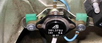
The main fuse box on the “ten” is located in the car’s interior, to the left of the steering column at the bottom. The photograph below shows the appearance of the safety block and symbols.
So, let's look at which parts of the electrical chain the devices located in the safety block are responsible for.
In addition to the fuses themselves, this housing also contains some relays responsible for the operation of electrical components.
- K1 – housing of the relay device that monitors the proper condition of the lighting lamps;
- K2 – housing of the relay device that regulates the operation of the wipers;
- K3 – housing of the relay device that interrupts the electric current going to the turn lamps;
- K4 – housing of the relay device, including low-beam headlights;
- K5 – housing of the relay device, which includes high-beam headlights;
- K6 – housing of an additional relay device;
- K7 – relay device housing, including a heating system for the rear windshield;
- K8 – housing of the backup relay device;
Under the designations F1 to F20 there is a system of fusible safety devices. A significant part of your car's electrical circuits is protected by safety components. Each of them is designed for a specific current. Without protection, the electrical circuits responsible for charging the battery, leading to the generator system, to the ignition and engine starting system remain unprotected.
In order to detect and replace a faulty fuse, we recommend that you use a special table. For replacement, we recommend using original safety elements. Some of the fuses presented in the table may not be present on your vehicle. This is due to the peculiarities of the configuration of electrical devices of a particular model.
So, let's consider the purpose of each of the elements of the VAZ 2110 safety block:
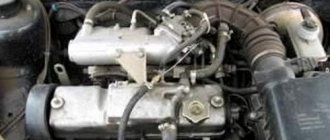
Hello, visitors to our site! I want to tell you a story that happened two weeks ago. Arriving from work one day, I, as usual, opened the hood to see if everything was in order and discovered that the peephole on the battery was white.
Of course, this “eye” shows the condition of only one battery bank, but still I decided to check the voltage with a multimeter. I have a new battery, a little over a month old, and this peephole “tells” me that the battery needs charging. Taking a regular multimeter, I measured the voltage at the battery terminals with the engine turned off. The voltage was 12.3V. Then I started the engine and measured 13.7 at idle without load, and with the low beams, heater and radio on, only 12.8, and this is not enough to charge the battery, and the battery charging light did not light up (it lights up when you turn the key in the first position). After thinking a little, I decided to check the condition of the generator brushes.
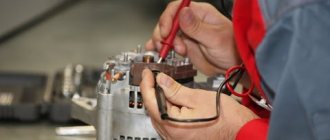
How to disassemble the generator on a VAZ 2110? (Video)
Repairing a generator on a VAZ 2110 car with your own hands is quite possible.
You can either partially repair the element or completely replace it. It all depends on the specific situation and the degree of wear of the device. According to the operating manual, a routine check of the condition of the generator should be carried out every 50 thousand kilometers. But this is provided that the device is working properly.
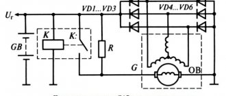
Device diagram
It happens that the generator begins to act up ahead of schedule and the battery does not charge properly. Actually, it serves to ensure the operation of the source of electricity to power all cars - the battery.
We advise you to rely not only on our instructions, but also on video lessons that will allow you to carry out repairs and replacements with your own hands, even without much experience.
Troubleshooting
The first step is to determine whether your generator is actually the source of the problem. To check, you need to carry out a series of sequential activities.
- Start the engine and let it warm up to operating temperature.
- Increase the crankshaft speed to approximately 3 thousand rpm.
- Turn on all the headlights, activate the high beams, start the heater, emergency lights, heated glass, and wiper blades. That is, all electricity consumers should be turned on as much as possible.
- Measure the voltage on the battery.
- If the device shows less than 13V, then a short circuit or break has most likely occurred in the generator windings.
- Another option is a breakdown of the voltage regulator, oxidation of the contacts of the excitation winding ring.
You can check for breaks and the condition of other elements of the generator only by dismantling it. But if you don’t have any experience in disassembling a generator, then you shouldn’t try to go there with your own hands. Replace the entire assembly or entrust the repair to professionals.
To disassemble, remove and repair or replace the generator, you will need to do the following.
- Drive onto an inspection hole or overpass to have access to the bottom and engine compartment.
- Remove the battery, otherwise it will not allow you to get to the nut that holds the generator you are looking for.
- Next, the same nut and adjustment bar are removed. Here you will need a 17 mm wrench. Use an extension cord. This will make the task easier; you will have to apply less force to unscrew the fastener.
- In the engine compartment, remove the shield that performs dirt protection functions.
- Now the drive belt is removed and the wires are disconnected.
- Be sure to remove the protective cap and use a 10mm wrench to unscrew the nut that holds the tip and positive cable of your battery.
- There is another nut on the fixing bracket, which will also have to be unscrewed.
- That's it, you can remove the generator. Just remember to pull out the long bolt first.
- When removing, keep an eye on the buffer sleeve. It won't be good if you lose it.
Dismantling works
This completes the procedure for removing the generator. You can proceed with partial repairs or complete replacement of the unit.
Often, the solution to a poorly functioning alternator is simply adjusting the belt.
Belt
- For the device to work effectively, it is necessary to ensure normal deflection of the belt;
- The deflection size should be 6-10 millimeters with a force of 98 N or 10 kgf;
- To adjust or replace the belt, you need to move the generator slightly to the side, towards the cylinder block;
- By rotating the adjusting bolt, you can adjust the belt tension.
If this measure does not help, you will have to pay attention to the voltage regulator and brushes.
Brushes and regulator
It is not recommended to repair the generator brushes, as well as the voltage regulator if they are worn out.
Experienced specialists advise purchasing a complete unit that includes both elements. Replacement is completed in a matter of minutes.
Brushes
But we will definitely tell you how you can change the brushes on your car’s generator with your own hands.
- Disconnect the negative terminal from the battery and remove the battery.
- Remove the generator following the instructions above.
- You can replace the brushes without removing the generator, but this causes certain difficulties. It is much easier to remove the unit.
- Remove the cover, which is the protective casing of the generator.
- The wires and the generator itself are disconnected from the brushes. To do this, simply unscrew a couple of bolts.
- On the right side of the dismantled device there is a nut that can be unscrewed by 13 millimeters with a spanner.
- Now lift the voltage regulator lever, which will allow you to get to the brushes.
- Using new brushes, install them in place of the old ones and reassemble the assembly in reverse order.
When reassembling, proceed as carefully as possible so as not to damage the repaired generator with your own hands.
Quite often, the cause of failure is not the generator itself, but its relay.
There may be several reasons for replacing the relay.
Replacing the VAZ 2110 generator relay on your own
Relay regulator VAZ
Replacing the VAZ 2110 generator relay can be done in two ways: with removing the generator and without removing it. Both options can be done at home, although the second involves fewer manipulations with the car. But despite this, the first option may be simpler for some. Anyone can replace the VAZ 2110 generator regulator relay if they read and study the instructions below.
How to remove the relay regulator?
Removing the relay is allowed only after disconnecting the terminals from the battery.
To dismantle the device yourself, you will need a screwdriver with a Phillips or flat head. It all depends on the bolt that secures the regulator. The generator unit and the drive belt do not need to be dismantled. The cable is disconnected from the regulator and the bolt that secures it is unscrewed.
User Viktor Nikolaevich spoke in detail about the dismantling of the regulatory mechanism and its subsequent replacement with a car.
Checking the generator relay on a car
Replacing the VAZ 2110 generator regulator relay
However, before proceeding with the replacement, you need to check whether the problem is really with a faulty relay. In this case, it will be checked directly on the car. To do this you need:
- Take a voltmeter with a scale of 15-30.
- Turn on the engine.
- Turn on the headlights (see Replacing headlights on a VAZ 2110: do it yourself).
- The motor must run for at least 15 minutes.
Note: you can turn on speed 2, but it is best to turn on speed 3, since this will use a little less gasoline. And the result will be achieved much faster.
- The voltage must be measured between the “B+” terminal and the generator ground. However, it should not be less than or more than 13.2-14.7 V.
- Replacing the relay is necessary if both undercharging and overcharging are observed.
Checking the removed relay
Replacing the regulator relay on a VAZ 2110 generator
It is advisable to check the relay together with the brush holder, since in some cases problems arise due to poor contact between the relay and the brushes. To check the regulator after removing it, you must:
- Turn on a 12 V lamp between its brushes.
- First, connect a power source with a voltage of 12 V to the “D+” relay terminal. If the relay is faulty, the lamp will light up.
- Then you need to take a more powerful current source - 15-16 V. If the relay does not work correctly, the light will go out.
Note: The lamp may be on or off in both cases. If it lights up in both places, it means there are breakdowns in the regulator. At the same time, if the light does not light, then there is no contact between the brushes, which can result from a broken wire.
Capacitor check
Generator relay VAZ 2110
By the way, many people confuse a faulty relay with a faulty capacitor (see Changing the capacitor (VAZ 2110 generator)), since the “symptoms” are quite similar. Thus, if after checking the relay, it is clear that it is fully operational, but the voltage generator is not working well, then you need to check the capacitor. It protects all electronic equipment from voltage surges. To check its operation, you should:
- Turn on the radio. If there is interference in its operation, then all is not well with the capacitor. The engine must also be turned on.
- You can check its serviceability using a megger or tester. When connected to a capacitor, the needle should quickly move to the side and then slowly return to its original position.
How are the blocks separated in the machine?
The main type of block is placed in the most convenient place for the driver. In this version of the VAZ it is located on the left side of the body directly at the steering wheel. Easy access to the unit is provided using a built-in button located next to the car's headlight control.
2 backup units with relays are located separately in the right and central parts of the console just behind the dashboard. One of the fuses shown below in the diagram will be located at a distance from the rest of the list - it can be found in a special compartment behind the main fuse block, next to the mounting block. To timely repair electrical equipment on a VAZ-2110, you need to learn how to quickly determine the location of a blown fuse, and also know which elements of the car its failure will affect.
Advice: very often one burnt valve can lead to replacing the vacuum booster on a VAZ-2110. That is why it is important to check not only the general condition of the fuse, but also the parts that interact with it, for example, the injector.
How to find out that it is the relay that is broken and not the generator itself
Many people believe that if the battery does not hold a charge, then the problem is in the generator. However, sometimes this can be caused by a faulty relay regulator. To check what exactly is not working, you need to do the following:
- Open the hood of the car.
- Start the engine. Put 2 or 3 speed on the gearbox.
- Remove the battery terminal.
Note: this is necessary to ensure that a short circuit does not occur in the system.
- If after this the machine still works, then the relay is faulty. But if the car stalls, then the reason is still in the generator.
Advantages of a three-level relay
The voltage regulator is mounted on board the machine, while the generator brushes and panel are mounted directly into the generator. Thanks to these three levels, the battery will remain charged for a long time, and its service life will increase significantly. These levels are:
- Minimum level. It is necessary for the car to work even in the hottest conditions. That is, it will not stall even in areas where the air temperature exceeds +20 degrees. In addition, the car can withstand even the highest slopes.
Note: this level is required in the summer.
- Level "norm". Allows the machine to operate under normal conditions.
- Level "maximum". Necessary for using the machine even at sub-zero temperatures. At the same time, the car will be able to start even with a discharged battery.
Additional block
It is located under the center console and is covered with a lid. One part is accessible from the right side.
Designation
p, blockquote 27,0,0,0,0 —>
- 15A - Ignition module, controller
- 15A - Canister purge valve, vehicle speed sensor, oxygen concentration sensor (heating), air flow sensor
- 15A - fuel pump, fuel pump fuse, injectors
- Electric fan relay
- Fuel pump relay
- Main relay (ignition relay)
The other part is on the left side of the console:
Decoding
p, blockquote 31,0,0,0,0 —>
- Central locking control unit
- Immobilizer block
- Relay for turning on rear fog lights.
On our channel we also prepared a video on this publication. Watch and subscribe.
Reasons for replacement
Relay replacement is needed in the following cases:
- The brushes are worn out. By the way, this is the main reason. The fact is that due to their wear, contact with the relay is lost, so due to lack of power, the generator will stop working.
- A breakdown is observed in the circuit, which leads to an increase in voltage in the system.
- Wire breaks causing loose contacts.
- Damage to the housing or fastenings. This is not something to joke about, as it can lead to an unwanted short circuit.
Relay replacement
Note: It is usually black and is attached to the generator with a yellow wire.
- Disconnect the negative terminal of the battery.
- Unscrew the two bolts securing the generator.
- Remove the yellow wire going to the relay from the generator.
- Remove the relay. Examine it carefully. If the brushes are worn out, replacement cannot be avoided.
- If any of the wires are broken or there are holes on its surface, then you can only get by by replacing them.
Note: you can simply insulate them without even replacing them with new ones. Although the relay is inexpensive - only 70 rubles.
- Check the new voltage regulator, and then attach it to the generator.
- Reconnect the yellow wire and battery terminal.
As noted earlier, you can replace the relay with your own hands. The main thing is to familiarize yourself with the work process in advance so that questions do not arise later. To do this, you can find photos in various auto repair magazines. It’s much easier to use videos, of which there are many on the Internet. Our instructions will also help in this difficult matter. But the price of home repairs will not exceed 100 rubles.
Problems with the battery: charging the VAZ 2106 and diagnosing faults
As a rule, before checking the regulator of a VAZ 2107, 2106 or any other car, it is necessary to review in general terms the design and operating principle of such a regulator.
Let's start with the fact that the design of the regulator may differ. Old VAZ 2106 models have outdated contact regulators. At the same time, newer versions already use an electronic regulator.
- So, the contact external regulator is still the basis. This is a semiconductor type device manufactured on a single board. The main element is the winding (brass wire is used), the winding consists of just over a thousand turns, and there is a copper core inside the winding. The winding has a constant resistance of 16 ohms.
The regulator also uses a group of tungsten contacts, an adjustment plate, and a magnetic shunt. A set of resistors is used in parallel, and their connection differs depending on what voltage is required. The resistors provide a maximum resistance of 75 ohms. All components are located in a textolite case, with contacts for connection brought out.
Let's move on. When the internal combustion engine starts, the crankshaft rotates, from which the attachments are also driven. The generator on many cars is no exception, that is, the rotor in the generator is also driven by the engine. So, when the engine rotates at a frequency of about 2 thousand rpm, the voltage at the generator outputs is no higher than 13 Volts.
In this case, the regulator does not turn on; the current goes directly to the excitation winding. However, when the engine rotation speed increases, as well as the generator rotor, the voltage regulator automatically turns on.
On a VAZ 2106, the relay regulator is connected to the generator brushes, as well as to the ignition switch. Also, the winding connected to the generator brushes actively reacts to the fact that the internal combustion engine speed increases and, as a result of such an increase, becomes magnetized.
Next, the core in the winding is pulled inward, which leads to the opening of the contacts on the internal resistors of one group and the closure of the contacts on the resistors of the other group. For example, when the speed is not high, only one resistor in the regulator remains closed, while when operating at high speeds, three resistors are closed, and the voltage on the excitation winding drops significantly.
Voltage regulator - its main functions
On a VAZ 2110 car, the voltage potential in the generator is formed under the influence of alternating current. This phenomenon becomes possible due to the presence of silicon diodes in the generating device of the vehicle. The generator rotor (the rotating component of the mechanism) operates according to the following diagram:
- First, the crankshaft begins to function, which is affected by the current;
- the crankshaft sets the movement of the rotor;
- After this, the generating device itself begins to work.
All stages of the sounded process are monitored by a voltage regulator, which is also often called a relay. It is this that is considered the main control unit of the generator.
Without a regulator, the current-generating mechanism of the VAZ 2110 will not perform its tasks, which are listed below:
- starting the generator;
- control (in offline mode) of current supply;
- “holding” in a certain voltage range.
The described relay cannot be repaired. In the event of a breakdown, the regulator must be replaced, which is done after checking the functionality of this unit.
The location system of the additional fuse box in the VAZ-2110
This block is located directly in line with the injector and to the right of the centrally located instrument panel. To remove the unit, you do not need to take the machine diagram and look for secret compartments - you just need to tighten the screws on the panel and easily remove the cover.
The photo below shows a diagram of the location of the fuses themselves, of which there are 6 in total, and their current strength is the same - 15A each fuse.
The diagram shows the location of the fuses responsible for:
- Operation of the ignition system controller.
- Regulation of current in oxygen sensors, air flow system and machine speed calculation.
- Correct fuel supply to the pump, relay and injectors.
- Fan operation when cooling the engine.
- Fuel pump operation.
- Direct ignition of all vehicle systems.
Despite the release date of the Lada Vesta Cross. in a VAZ-2110 car it is unlikely that the location of the main blocks will change. Thanks to the above diagrams, you will now be able to pre-calculate the problem of the machine simply by checking the condition of the fuses and relays.
How to check the relay on a VAZ 2110?
To analyze the condition of the regulator, you need to purchase a voltmeter, which has a measuring scale in the range of 15–30 volts. The check is performed as follows:
- start the car engine at medium speed and let it run for a quarter of an hour (the operation is carried out with the headlights on);
- A voltmeter is used to determine the voltage between the “ground” of the generating device and the “plus” on the battery.
If the measurement shows a voltage value from 13.5 to 14.2 volts, replacing the regulator is not necessary. But in situations where the voltage has a different value, indicating a constant overcharging or undercharging of the battery, the relay needs to be replaced.
You can also remove the voltage regulator and check it together with the generator brush holder. To do this, a 12-volt light bulb with a power of 1–3 watts is placed between the brushes, a power source is connected to the “ground” and the positive terminal of the battery, from which a voltage of 12 volts is first supplied, and then 16 volts.
If the light comes on at 12 volts and goes out at 16, replacing the regulator on a VAZ 2110 is not necessary. If the lamp does not light up, this indicates that there is no required power contact between the relay terminals and the brushes, or that a break has occurred. And the burning of the lamp at 12 and 16 volts indicates a breakdown of the regulator.
How the relay works
This device on the VAZ-2107 (both carburetor and injector) is located in the same housing as the brush mechanism.
Its main purpose is to stabilize the voltage coming out of the generator. Not so long ago, relays made in the form of an electronic board were sold in stores. It had one drawback - a relatively short service life. Such devices could not be disassembled and were simply replaced with serviceable ones when they broke down.
Modern analogues are slightly smaller in size and use a semiconductor. The old type of relay can no longer be found. The new version is in no way inferior to it functionally and is also capable of reliably regulating voltage in the range from 13.2 volts to 14.8. Exceeding the last value when measured with a tester on the battery clearly indicates a breakdown of the relay.
How to replace the generator voltage relay?
If you have some skills, removing and disassembling the mechanism described in the article does not cause difficulties for a person. The most difficult thing is to change it for the first time, and subsequent replacements, as a rule, take place quickly and without problems.
The regulator on a VAZ 2110 is dismantled according to the following scheme:
- disconnect the negative terminal from the battery;
- disconnect the drive block from the terminal marked “D+”;
- unscrew the nut, which is located under the rubber boot (it needs to be moved a little to the side);
- disconnect all existing wires in the contact pin;
- unscrew the nut in the generating device circuit (this fastener secures the terminal) and remove it.
Then you will need to remove the generator casing by unscrewing the nuts (there are three of them) that hold it in place, as well as dismantle the relay housing and remove the screw securing the disassembled mechanism from the rectifier compartment. Now the VAZ 2110 voltage regulator can be easily removed. You can install a new device instead. After replacing the relay, all the described steps are performed in the reverse order.
Replacing the battery charging relay
1. Disconnect the negative cable from the battery.
2. Turn off the minus generator
3. Unscrew the nut securing the “plus” of the generator and remove the plastic cover by bending the latches
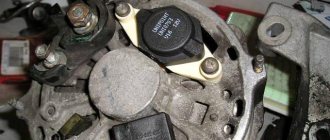
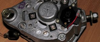
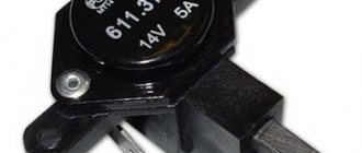
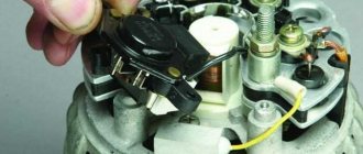
4. Unscrew the two screws securing the voltage regulator (the generator has been removed for clarity) and remove it
The brushes must protrude from the voltage regulator by at least 5mm. My brushes protruded 1-1.2 cm.
Almost new, one might say. The brushes did not jam and were generally in good condition. Next, I cleaned the terminals of the battery itself and the “+” contacts or, as it is also called, the “B” output of the generator. I measured the voltage again - the picture was the same. The charge is bad. After weighing all the pros and cons, I decided not to disassemble the generator (if you decide to disassemble the generator here), but to replace the voltage regulator (despite the good condition of the brushes). This element in the generator is perhaps the cheapest. I bought it for 230 rubles. Having replaced the regulator and started the engine, I hastened to check the voltage. The long-awaited reading of 14.1V appeared on the multimeter. Having turned on the low beam, stove, speakers and heated glass, the device showed 13.6V. The battery began to charge again. Next, I removed the battery and charged it at home. Now, two weeks later, all battery readings are normal. I hope this article will be useful to someone.
The voltage regulator on a modern car automatically and continuously adjusts the excitation current of the generator. Moreover, this process proceeds in such a way that when the current load and rotation speed of the generator changes, the value of its voltage remains in a strictly defined range.
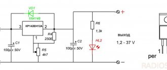
Three-level generator voltage regulator for the “ten”
When the heating system, headlights and other additional loads are turned on on the VAZ 2110, the car battery discharges very quickly. This phenomenon is observed even when the “native” generator relay is functioning normally. A three-level regulator allows you to get rid of this problem. You can purchase it at any auto store, equip yourself with a simple set of tools (terminal pliers, a knife, an S10 open-end wrench and a Phillips screwdriver) and install it on the car yourself.
The three-level mechanism is mounted as follows:
- first remove the old relay according to the algorithm given above;
- grind the ends of the spacer bushing using a file (this operation ensures more reliable contact with the diode bridge);
- a new element with a brush holder (sold as a set) is installed in place of the relay;
- Sealant is used to seal the cable entry point;
- put back the plastic casing;
- lay the cable along the standard wiring to the area where the relay is mounted, and secure the new wire tightly with small plastic clamps.
It is recommended to connect the housing of the installed voltage relay and the autogenerator using a reliable shunt. This ensures the necessary contact of the device with ground. However, you can do without a shunt.
The mounted three-level mechanism should be checked with a tester at full consumer load (window heating, stove, headlights, etc. are turned on). At maximum, the device should show 14.5 V, in normal mode - 14.1 V, at minimum - about 13.4 V.
VAZ 2110 generator voltage regulator - how to check and replace
The vehicle's electrical circuit includes a device such as the voltage regulator of the VAZ 2110 generator. Its task is to limit the output voltage of the generator and bring it to optimal values in accordance with the parameters of the on-board equipment. In this article we will tell you how this device works, what malfunctions are typical for it, how to check and replace. We will also give you detailed recommendations that will allow you to continue driving with a faulty regulator.
OTHER REASONS FOR NO CHARGING
If the battery is not charged or is insufficiently charged, in addition to a faulty voltage regulator, there may be other reasons related to the generator:
- The belt is poorly tensioned;
- Poor contact or break in the wires supplying power;
- Faulty rotor or stator winding;
- Poor contact of the brushes with the rotor commutator, the brushes are simply worn out.
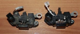
New and worn alternator brushes
What is a generator voltage regulator?
The voltage regulator is a relay that closes and opens the electrical circuit at the right times. In cars, this relay works to limit the output voltage. The fact is that a generator with a certain rotor speed can produce a specific voltage. Since the rotor speed constantly depends on the crankshaft speed, the voltage changes accordingly. To maintain a given voltage, a special device was developed that helps create an output voltage within the range of 12 - 14 Volts.
The first voltage relay was made in the form of an electromagnet, which opened with a change in the input value, and closed again when the voltage dropped, thus, the voltage in the electrical circuit of the on-board system was kept within a strictly specified range. This range is necessary for the correct operation of electrical devices. If you increase the voltage to values exceeding the nominal values, the device will simply fail.
Another stage in the development of mechanical relays was the emergence of a semiconductor device, which works much more accurately and reliably. A semiconductor relay has smaller dimensions and a special indicator that indicates whether the device is working or has failed.
The main difference between a mechanical relay and a semiconductor relay is the ability to make adjustments. If the output voltage of the supply circuit has changed, then by changing the position of a special device, you can set new values that will allow the relay to operate for a long time.
If the regulator relay fails, it must only be replaced.
Operating principle of the relay regulator
The presence of a built-in resistor device, as well as special circuits, makes it possible for the regulator to compare the voltage parameter produced by the generator. If the value is too high, the controller is switched off. This allows you to prevent overcharging of the battery and failure of electrical equipment that is powered from the network. Problems with the device will damage the battery.
Switch winter and summer
The generating device operates stably regardless of the ambient temperature and season. When its pulley is set in motion, current is generated. But in the cold season, the internal structural elements of the battery may freeze. Therefore, the battery charge is restored worse than in the heat.
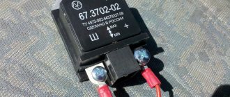
The switch for changing the operating season is located on the relay body. Some models are equipped with special connectors; you need to find them and connect the wires in accordance with the diagram and symbols marked on them. The switch itself is a device thanks to which the voltage level at the battery terminals can be increased to 15 volts.
Malfunctions and checking regulators on a VAZ
During operation, the voltage regulator may fail. In VAZ 2110 cars of all editions, a semiconductor relay is used, which contains graphite generator brushes. A relay malfunction can lead to the following consequences:
- Failure of all vehicle network devices. Usually, the first thing that happens is that all the lamps in the lighting devices burn out. If this suddenly happened, the relay has failed because the output voltage exceeded the rated values.
- Recharging the battery . Overcharging a galvanic cell is also unacceptable. This can lead to boiling of the electrolyte and subsequent damage to the battery.
- Small charge . As many car enthusiasts say, “undercharging” occurs. A weak battery will not be able to fully ensure reliable engine starting.
In total, there are only two malfunctions of the voltage regulator relay. These are: failure of the relay (charging does not occur, or the battery is overcharged) and its incorrect operation (the relay works, but passes too little voltage, which is not enough to charge the battery). All relay malfunctions can be identified by many external signs, as well as through diagnostics.
The most reliable way to check the voltage regulator is to measure the electrical value at the battery terminals with the engine running and idling. The normal voltage is considered to be between 13.5 and 14.2 Volts. If the voltage level exceeds these values or is lower, it means that the voltage regulator is faulty and must be replaced.
In addition, there are other signs of a relay failure, after which the device usually begins to be checked:
- The charging indicator light came on while the engine was running. As the speed increases, the lamp goes out.
- Dim headlights when the engine is running. Likewise, as the speed increases, a brighter glow can be observed.
- Too bright headlights and subsequent burnout of the lamps also indicate incorrect operation of the relay.
- If the battery charge is sufficient for a small number of starts, it means that the relay does not fully provide the required charge.
What does the second set of fuse boxes do?
The symbols F1-F20 indicated below in the electrical diagram are the elements that characterize the set of fuses. The electrical circuit in a VAZ- 2110 is protected using fuses based on the specific calculation of the model for the rated current value specified at purchase.
At the same time, fuses are not responsible for the quality operation of the circuit consisting of a sample battery, a separate type of generator circuit, the ignition system and engine valve starting. To replace a faulty fuse in this mounting block, follow the following plan:
- Find a fuse that has mechanical damage or its body has burned out;
- According to the instructions, determine and eliminate the reason why it turned out to be faulty;
- Install a new fuse using the backup model.
Tip: Never try to replace a fuse with special jumpers. In the future, this will lead to failure of those devices that are assigned to this fuse.
Diagram with designations for the second set of fuses in the block
All fuses are divided according to their interaction with electrical equipment as follows:
- F1 (current 5A) - fuse responsible for the set of lamps that illuminate the license plate, the entire instrument panel, including the side lights and lighting in the trunk.
- F2 (current 7.5A) - element that regulates the low beam on the left headlight.
- F3, F4 (current 10A) - responsible for the operation of high beam in the left headlight and right fog lamp, respectively.
- F5 (with a current of 30A) - is responsible for the electric window motor at the front and rear car doors.
- F6 (with a current of 15A) - refers to the operation of a portable lamp.
- F7 (with a current of 20A) - regulates the operation of the fan motor in the cooling system of a 16-valve engine, as well as the operation of the sound signal.
- F8 (with a current of 20A) - supplies current to the heating elements located on the rear window. In addition, together with the contacts from the relay, it transmits current to the windshield.
- F9 (with a current of 20A) - is responsible for the operation of the recirculation valve. It also interacts with the windshield wiper and washer sensors and headlights.
- F10 (with a current of 20A) - is a backup fuse.
- F11 (with a current of 5A) - regulates the operation of lamps with side lights on the starboard side.
- F12 and F13 (with a current of 10A) - both fuses regulate the operation of the right headlight, responsible for the low/high beam, respectively.
- F14 (current 10A) - adjusts the light from the left fog lamp.
- F15 (with a current of 20A) - interacts with the electric heating of the driver and passenger seats. Protects the car from unauthorized blocking of the central locking in the trunk.
- F16 (with a current of 10A) - transmits current to the breaker relay to ensure the operation of the direction indicator of the left and right headlights, and is also used to give an emergency signal (when using the emergency signal mode on the VAZ-2110).
- F17 (current 7.5A) - works with the car interior lighting lamp, brake light lighting, individual lighting of the ignition system switches and regulates the operation of the trip computer.
- F18 (with a current of 25A) - illuminates the glove compartment, supplies current to the heating system controllers and the cigarette lighter on the dashboard.
- F19 (with a current of 10A) - is responsible for the operation of the door locks, and also informs the driver about the presence of a malfunction in the brake light lamps or side light elements.
- F20 (current 7.5A) - works with the lamps of the rear pair of fog lights of the VAZ-2110.
READ Where is the Volkswagen Turan engine number located?
Having dealt with the fuses, you can also learn about how to bleed the brakes on a VAZ-2110. Often the operation of the braking system greatly affects the operation of the car in general and electrical equipment in particular.
What to do if the voltage relay fails?
It happens that the relay fails at the most inopportune moment, when you still have a drive home and the battery is not charging. The battery capacity in economical mode can ensure fairly long engine operation, which will allow you to get to the repair site without any problems. Below we will provide a list of recommendations that will help you drive, as they call it, “on battery power” and not stall.
- If the battery is overcharged, the relay must be disconnected from the circuit. To do this, the contact wires are removed from it and left hanging. In the case of the “ten”, it is enough to unplug the plug with the wire from the generator brush connector. Thus, battery charging is turned off, and further movement will no longer harm the battery.
- Many experts suggest going the other way - turning off the generator excitation winding . To do this, remove the corresponding fuse. However, this can be done if you know where the fuse is located.
- If the battery is weakly charged, then there is practically no reason to panic. To get to your destination, you need to maintain high speeds in order to, at least a little, bring the voltage value to the nominal value. to maintain the speed at 3000 rpm for a few seconds using the gas pedal This will prepare the battery for the next start.
- Avoid using music, power windows, headlights (especially high beams), and other electrical devices unless their use is absolutely necessary. This will save battery power well.
VAZ 2112 fuse diagram
With an 8-valve and 16-valve engine, it is equipped with a main mounting block, and since 2008 an additional console has been added. A diagram with element markings is printed on the left side of the main block cover and placed below.
The designations of all elements are presented below. You can find the transcript in the table.
| Circuit breakers | Power, A | What protects |
| F1 | 5 | Lamps for turning on the license plate lighting, instruments, side lights, trunk, left side. |
| F2 | 7,5 | Low beam |
| F3 | 10 | Further |
| F4 | 10 | PTF |
| F5 | 30 | Door windows |
| F6 | 15 | Portable lamp (socket) |
| F7 | 20 | Engine cooling fan. Sound signal. |
| F8 | 20 | Rear window heating element. Relay for turning on the heated rear window. |
| F9 | 20 | Recirculation valve. Cleaners, windshield and headlight washers (wiper fuse). Relay for turning on the heated rear window. |
| F10 | 20 | Spare |
| F11 | 5 | Starboard side marker lamps |
| F12 | 7,5 | Middle left |
| F13 | 10 | Far left. Power indicator lamp |
| F14 | 10 | Left PTF |
| F15 | 20 | Electrically heated seats. Trunk lock lock |
| F16 | 10 | Turn signals and emergency lights. |
| F17 | 7,5 | Interior lighting. Ignition switch. Stop signal. Watch. |
| F18 | 25 | Glove compartment lighting. Heater controller. Cigarette lighter fuse. |
| F19 | 10 | Locking door locks. Relay for monitoring the serviceability of brake light lamps and dimensions. Direction indicators. Reversing light. Generator excitation winding. On-board control system display unit. Instrument cluster. Watch. |
| F20 | 7,5 | Rear fog lamps. |
- K1 - lamp health monitoring;
- K2 - windshield wiper;
- KZ - direction indicators and emergency lights;
- K4 - switch on low beam;
- K5 - high beam;
- K6 - additional relay;
- K7 — heated rear window;
- K8 - rear PTF.
Starter fuse and relay
Installed on the device itself between the engine and the fan radiator. If signs of a malfunction appear, it is better not to delay replacing the element and install a new relay.
Fuel pump fuse and relay
Located in the additional interior installer - No. 3. Responsible for the fuel pump relay No. 5.
Relay and fuse for cigarette lighter
No. F18 is rated at 25 Amps.
Stove
The 25 A element F18 is responsible for protecting the operation of the electrical circuit of the heater motor.
Turn signals
The elements are marked as F19 and are rated at 10 Amps.
Brake lights
Located in the main block - No. F17. Its power is 7.5 A.
Where is the alarm fuse located?
Cooling Fan
The F7 element with a power of 20 Amperes is responsible for its protection.
Which fuse goes to the radio?
Window lifters
Fuse and relay for central locking VAZ 2112: where is it located
They can be found in a separate box behind the main mounting block.
Ignition
The main relay is located in the additional cabin unit, where it is number 6.
Reverse
F19 with a rating of 10 Amperes is responsible for the lamps.
Fogs
Protected by three inserts: right - F4, left - F14, and rear - F20. The power of all PTFs is 10 Amps. In case of tuning, you may need to replace them with new ones along with the fog lights. The connection occurs via switch K8.
Lamp health monitoring relay
Marked as K1 in the main block of the VAZ 2112.
Brake
Installed under the brake pedal.
Relay and fuse for injectors
The additional element F3 is rated at 15 Amps.
Fuse for interior light
The F17 element with a power of 7.5 A is responsible for the safe operation of the VAZ 2112 interior lighting lamp.
Number plate illumination
Corresponds to F1 with a rating of 5 Amps.
Generator
A three-level relay voltage regulator is located on the device. It is better to replace the factory element with a new one, since three-level voltage regulation often leads to a short circuit.
Heated rear window
Relay K7 is responsible for turning on. Protects the F8 electrical circuit with a rating of 20 Amps.
Seat heating
It is protected by a 20 Amp F15 insert.
Wiper relay
This is a K2 and without its stable operation there will be no washer supply to the windshield, and the wipers will not be able to do their job.
Charger
They placed it next to the device - one of the few elements of this kind under the hood of a car.
Low and high beam VAZ 2112
It is protected by fuses F2 and F12 (left and right headlights), and the high beam is protected by F3 and F13 (left and right). The first has a rating of 7.5 A, and the second has a rating of 10 A.
Fuse for the dashboard of VAZ 2112
Located in the wiring harness leading to the instrument panel from the battery.
Dimensions
There are 2 fusible elements - F1 and F11, left and right. The power of both is 5 Amperes. Factory fuses require replacement due to the fact that the dimensions often burn out due to their malfunctions.
Heated seats
It is protected by an element marked F15 for 20 Amperes.
VAZ 2112 speedometer fuse: where is it located?
Opening the trunk
This is an F1 and is rated at 5A.
Fuse F6
Responsible for protection against burnout of the car socket. Its rating is 15 Amperes.
VAZ 2112: fuse F17 blows
Most often, this element, which is responsible for interior lighting, fails due to a battery failure. Its power is 7.5 A.
Fuse F19
Responsible for protecting the brake light, reversing lights and dimensions.
Relay K1
An element of lamp serviceability, which in older versions is replaced by a jumper.
Relay K6
Speed sensor
Located on the wiring harness leading to the device.
Replacing the generator regulator on a VAZ 2110
After detecting all of the above faults, it is necessary to replace the relay. To do this, you need to know exactly which relay is installed on your car. The fact is that depending on the car model, different generators are used. Modifications of the VAZ 2110 also have different generating devices.
Conventionally, regulators can be divided into two types: for injection cars and carburetor cars. They have few design differences, but the parameters on the basis of which they work may differ.
After determining the type of relay, the exact same new regulator is purchased. Then, disconnect the negative terminal of the battery and remove the plug from the relay connector. Unscrew the two screws securing the relay and unscrew the ground wire nut. Remove the old brushes and install new ones in their place. Installation is carried out in reverse order.
This completes the replacement of the VAZ 2110 voltage regulator.
Where is the relay and fuse for the VAZ 2110 fuel pump located?
They are located in an additional mounting block, which is located under the hood of the car. Their general characteristics differ little whether the engine has 8 or 16 valves. You can also find out what the relay looks like from the photo. And about the replacement process - from the video.
Required tools and procedure for removing the relay
Of all the tools for dismantling the relay, only wrenches are needed to unscrew the nuts: 8, 13 and 15.
- The first step is to disconnect the wires from the battery;
- Remove the air filter;
- Disconnect the wires connecting the device to the traction relay;
- Unscrew the power cable fastening nut with wrench 13;
- Unscrew the starter mounting nuts with a wrench 15;
- Remove the starter itself;
- Unscrew the nut securing the lower terminal of the traction relay;
- Disconnect the remaining wires;
- Unscrew the relay .
After all stages, the starter relay is removed.
Attention! The lower starter mounting nut is unscrewed with some force.
Replacing the VAZ 2110 generator relay on your own
Relay regulator VAZ
Replacing the VAZ 2110 generator relay can be done in two ways: with removing the generator and without removing it. Both options can be done at home, although the second involves fewer manipulations with the car. But despite this, the first option may be simpler for some. Anyone can replace the VAZ 2110 generator regulator relay if they read and study the instructions below.
Location of the turn relay VAZ 2110
The number K4 is easy to find among others in the main fuse block.
Where is the starter relay located on a VAZ 2110
Located in the additional fuse box. To find it, you must first look on the front panel near the passenger seat for a small plastic cover with a button that serves as a shutter. After pressing the last one, this cover opens. You can determine the location of this device among others using a diagram, which every car owner should have. If it is not there, then most likely it will be the second relay, on the right in the top row.
Checking the generator relay on a car
Replacing the VAZ 2110 generator regulator relay
However, before proceeding with the replacement, you need to check whether the problem is really with a faulty relay. In this case, it will be checked directly on the car. To do this you need:
- Take a voltmeter with a scale of 15-30.
- Turn on the engine.
- Turn on the headlights (see Replacing headlights on a VAZ 2110: do it yourself).
- The motor must run for at least 15 minutes.
Note: you can turn on speed 2, but it is best to turn on speed 3, since this will use a little less gasoline. And the result will be achieved much faster.
- The voltage must be measured between the “B+” terminal and the generator ground. However, it should not be less than or more than 13.2-14.7 V.
- Replacing the relay is necessary if both undercharging and overcharging are observed.
Checking the removed relay
Replacing the regulator relay on a VAZ 2110 generator
It is advisable to check the relay together with the brush holder, since in some cases problems arise due to poor contact between the relay and the brushes. To check the regulator after removing it, you must:
- Turn on a 12 V lamp between its brushes.
- First, connect a power source with a voltage of 12 V to the “D+” relay terminal. If the relay is faulty, the lamp will light up.
- Then you need to take a more powerful current source - 15-16 V. If the relay does not work correctly, the light will go out.
Note: The lamp may be on or off in both cases. If it lights up in both places, it means there are breakdowns in the regulator. At the same time, if the light does not light, then there is no contact between the brushes, which can result from a broken wire.
Capacitor check
Generator relay VAZ 2110
By the way, many people confuse a faulty relay with a faulty capacitor (see Changing the capacitor (VAZ 2110 generator)), since the “symptoms” are quite similar. Thus, if after checking the relay, it is clear that it is fully operational, but the voltage generator is not working well, then you need to check the capacitor. It protects all electronic equipment from voltage surges. To check its operation, you should:
- Turn on the radio. If there is interference in its operation, then all is not well with the capacitor. The engine must also be turned on.
- You can check its serviceability using a megger or tester. When connected to a capacitor, the needle should quickly move to the side and then slowly return to its original position.
Useful tips
Always try and alternator clean Since contacts often oxidize due to moisture. And this greatly interferes with the normal operation of all electrical equipment. Often, deviations in the charging current occur precisely from dirt. Once you thoroughly clean the contacts and terminals , the fault disappears on its own, without any replacements or repairs. Cleanliness is the key to good health not only for a person, but also for a car.
vote
Article rating
How to find out that it is the relay that is broken and not the generator itself
Many people believe that if the battery does not hold a charge, then the problem is in the generator. However, sometimes this can be caused by a faulty relay regulator. To check what exactly is not working, you need to do the following:
- Open the hood of the car.
- Start the engine. Put 2 or 3 speed on the gearbox.
- Remove the battery terminal.
Note: this is necessary to ensure that a short circuit does not occur in the system.
- If after this the machine still works, then the relay is faulty. But if the car stalls, then the reason is still in the generator.
Advantages of a three-level relay
The voltage regulator is mounted on board the machine, while the generator brushes and panel are mounted directly into the generator. Thanks to these three levels, the battery will remain charged for a long time, and its service life will increase significantly. These levels are:
- Minimum level. It is necessary for the car to work even in the hottest conditions. That is, it will not stall even in areas where the air temperature exceeds +20 degrees. In addition, the car can withstand even the highest slopes.
Note: this level is required in the summer.
- Level "norm". Allows the machine to operate under normal conditions.
- Level "maximum". Necessary for using the machine even at sub-zero temperatures. At the same time, the car will be able to start even with a discharged battery.
Types of relay regulators
There are several types of automotive relay regulators:
- external - this type of relay allows you to increase the maintainability of the generator unit;
- built-in - installed in the rectifier plate or brush assembly;
- changing in minus direction - equipped with an additional cable;
- regulated by plus - characterized by a more economical connection scheme;
- for installation in AC units - the voltage cannot be adjusted when applied to the excitation winding, since it is installed in the generator;
- for direct current devices - relay regulators have the function of cutting off the battery when the engine is not running;
- two-level relays - today they are practically not used; they are adjusted using springs and a lever;
- three-level - equipped with a comparison module circuit, as well as a matching signaling device;
- multi-level - equipped with 3-5 additional resistor elements, as well as a control system;
- transistor samples - not used on modern vehicles;
- relay devices - characterized by more improved feedback;
- relay-transistor - have a universal circuit;
- microprocessor relays - characterized by their small size, as well as the ability to smoothly change the lower or upper operating threshold;
- integral - installed in brush holders, so they change when they wear out.
DC relay regulators
In such units, the connection diagram looks more complex. If the car is stationary and the engine is not running, the generator unit must be disconnected from the battery.
When performing a relay test, you must ensure that you have three options:
- battery cut-off when the vehicle is parked;
- limitation of the maximum current parameter at the unit output;
- possibility of changing the voltage parameter for the winding.
AC relay regulators
Such devices are characterized by a more simplified testing scheme. The car owner needs to diagnose the voltage level on the excitation winding, as well as at the output of the unit.
If an alternating current generator is installed in the car, then it will not be possible to start the engine “from a pusher”, unlike a direct current unit.
Built-in and external relay regulators
The procedure for changing the voltage value is carried out by the device at a specific installation location. Accordingly, the built-in regulators influence the generator unit. And the external type of relay is not connected to it and can be connected to the ignition coil, then its work will only be aimed at changing the voltage in this area. Therefore, before performing diagnostics, the car owner must make sure that the part is connected correctly.
The “Sovering TVi” channel spoke in detail about the purpose and operating principle of this type of device.
Two-level
The operating principle of such devices is as follows:
- Current flows through the relay.
- As a result of the formation of a magnetic field, the lever is attracted.
- A spring with a specific force is used as a comparing element.
- When the voltage increases, the contact elements open.
- Less current is supplied to the field winding.
In VAZ cars, mechanical two-level devices were previously used for regulation. The main disadvantage was the rapid wear of structural components. Therefore, instead of mechanical ones, electronic regulators began to be installed on these machine models.
These parts were based on:
- voltage dividers, which were assembled from resistor elements;
- A zener diode was used as a reference part.
Due to the complex wiring diagram and ineffective voltage level control, this type of device has become less common.
Three-level
This type of regulators, like multi-level ones, are more advanced:
- The voltage is supplied from the generator device to a special circuit and passes through a divider.
- The received data is processed, the actual voltage level is compared with the minimum and maximum values.
- The mismatch pulse changes the current parameter that is supplied to the excitation winding.
Three-level devices with frequency modulation do not have resistance, but the frequency of operation of the electronic key in them is higher. Special logic circuits are used for control.
Control by minus and plus
The circuits for the negative and positive contacts differ only in connection:
- when installed in the positive gap, one brush is connected to ground, and the second goes to the relay terminal;
- if the relay is installed in the minus gap, then one brush element must be connected to the plus, and the second - directly to the relay.
But in the second case, another cable will appear. This is due to the fact that these relay modules belong to the class of active type devices. For its operation, a separate power supply is required, so the plus is connected individually.
Photo gallery “Types of generator voltage regulator relays”
This section presents photos of some types of devices.
Remote device type
Built-in regulator
Transistor-relay type
Integral device
Device for DC generator
AC control device
Two-level device type
Three-level control device
Reasons for replacement
Relay replacement is needed in the following cases:
- The brushes are worn out. By the way, this is the main reason. The fact is that due to their wear, contact with the relay is lost, so due to lack of power, the generator will stop working.
- A breakdown is observed in the circuit, which leads to an increase in voltage in the system.
- Wire breaks causing loose contacts.
- Damage to the housing or fastenings. This is not something to joke about, as it can lead to an unwanted short circuit.
Relay replacement
Note: It is usually black and is attached to the generator with a yellow wire.
- Disconnect the negative terminal of the battery.
- Unscrew the two bolts securing the generator.
- Remove the yellow wire going to the relay from the generator.
- Remove the relay. Examine it carefully. If the brushes are worn out, replacement cannot be avoided.
- If any of the wires are broken or there are holes on its surface, then you can only get by by replacing them.
Note: you can simply insulate them without even replacing them with new ones. Although the relay is inexpensive - only 70 rubles.
- Check the new voltage regulator, and then attach it to the generator.
- Reconnect the yellow wire and battery terminal.
As noted earlier, you can replace the relay with your own hands. The main thing is to familiarize yourself with the work process in advance so that questions do not arise later. To do this, you can find photos in various auto repair magazines. It’s much easier to use videos, of which there are many on the Internet. Our instructions will also help in this difficult matter. But the price of home repairs will not exceed 100 rubles.
Malfunctions
There are two main reasons why an alternator stops charging properly.
| Cause | Peculiarities |
| Device overload | This happens to those who like to install numerous additional equipment that is powered by a generator, that is, it requires electricity. These could be speakers, electric pumps, video devices, etc. A standard generator is not designed for such loads, and therefore loses efficiency |
| Battery and alternator mismatch | To ensure the operation of electrical equipment additionally installed on the car, many decide to install a more powerful battery with a standard generator. A mismatch in power leads to the fact that the generator ceases to provide proper charging to the more powerful battery. So he simply does not have enough resources for this |
What charge does the generator produce?
Many people are interested in the question of how much a generator should produce for normal operation.
Here the parameters directly depend on the current state of the car.
- If the engine is cold and just turns on, then the voltage will normally be 14.1-14.4 Volts;
- If you check the voltage after long trips in traffic jams, then the generator will produce less, about 13.9-14.1V.