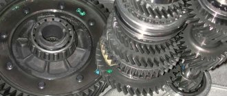
The clutch and gearbox are traditional components of any domestic or foreign car. The transmission is the element that ensures the supply of torque from the power unit to the wheels. If previously most vehicles were equipped with a manual transmission, today more and more motorists prefer hydromechanical automatic transmission. This is partly due to the fact that driving the car is easier, since there is no clutch pedal, and gear shifting occurs automatically.
Automatic transmission cross-section
The role of automatic transmission with hydromechanical control
To instantly start after pressing the gas pedal, and to protect the engine from overload, a transmission is installed in the car. It is also capable of changing torque, accelerating or decelerating the car. This transmission unit is called a gearbox - gearbox.
According to the type of gear shift, manual and automatic transmissions are distinguished:
Hydromechanical control facilitates and simplifies the driver’s work, removing some of the “responsibilities”. The smoothness and quietness of the automatic transmission increases driving comfort when starting and accelerating. The GMP also protects the engine and gearbox from dynamic loads that the driver can create by constantly “squeezing” the gas.
Main elements of a hydromechanical gearbox:
Read 5 Decent Automatic Motorcycles
Torque converter functions
A hydromechanical gearbox operates due to the movement of fluid pumped by an oil pump. The main “consumer” of oil is the torque converter (GDT). The gas turbine engine converts and transmits torque from the crankshaft to the transmission through fluid action.
Structurally, a gas turbine engine is a set of bladed wheels “locked” in a sealed donut-shaped chamber:
The hydromechanical transmission begins to work when the engine starts: the oil pump and pump wheel turn on. Liquid gets onto the wheel blades and spins around the axis of the gas turbine engine. Under the influence of centrifugal force, the oil is thrown onto the turbine blades, passes through the reactor and returns to the pump wheel. Under the pressure of the flow, the turbine blades begin to rotate, transmitting torque along the shaft to the gearbox.
The higher the engine speed, the faster the turbine wheels rotate, and the torque decreases. Without the reactor, the donut would only operate in fluid coupling mode, transmitting rotation without transformation. At the moment when the speeds of the pump and turbine are equalized, the reactor begins to rotate freely, increasing the pressure of the liquid falling on the pump blades.
Most of the engine energy is spent moving and heating the oil in the gas turbine engine. As a result, overall efficiency decreases and fuel consumption increases. To eliminate this drawback, a locking clutch with a friction lining is installed in the donut. When the clutch is engaged, the engine and transmission are firmly coupled, and torque is transmitted without loss.
The torque converter gear ratio reaches a maximum of 2.5 - 3, which is not enough for stable engine operation in different vehicle driving modes. It is not possible to engage reverse gear, since the wheels of the gas turbine engine only rotate in one direction. To compensate for these shortcomings, the hydromechanical gearbox is equipped with an additional unit.
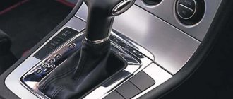
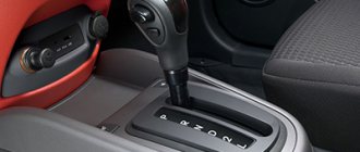
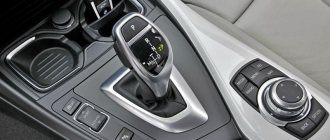
Shifting the automatic transmission gear selector on the go
General transmission device
The hydromechanical transmission consists of a torque converter and a manual gearbox. The torque converter does not provide the required range of gear ratios at high efficiency, disconnecting the drive shaft from the driven shaft and driving the vehicle in reverse. Therefore, torque converters are used in cars in combination with mechanical step transmissions, i.e. combined hydromechanical transmissions.
The torque converter consists of impellers with blades: drive (pump), driven (turbine) wheels and a stationary impeller that receives the reactive torque. Each impeller is mounted on its own shaft: the pump wheel is mounted on the engine flywheel shaft; the turbine wheel is mounted on the input shaft of the gearbox; The impeller is connected to the stationary shaft through a freewheel roller mechanism. The gearbox (two-stage) consists of a primary, secondary and intermediate shaft with gears, friction clutches for downshifting and “direct” gears and a connection between the pump and turbine wheels, a ring gear and a gear clutch for engaging the reverse gear with a pneumatic cylinder and a spring on the rod, a large and small gear pumps, centrifugal regulator. When the engine is running, the pump wheel acts on the liquid with its blades, forcing it not only to rotate with it, but also to move along the blades towards the outlet, as a result of which the fluid flow passes through the turbine wheel, then through the reactor and returns to the entrance to the pump wheel. The liquid circulates in a closed circle. In this case, the pump wheel transfers energy to the fluid flow, and it transfers energy to the turbine wheel. The magnitude of the energy transmitted by the flow and the force impact on the blades depend on the magnitude of the fluid velocity and its direction. In automotive torque converters, the reactor is connected to its fixed shaft through a freewheel roller mechanism. When the direction of the impeller torque changes (due to an increase in the angular velocity of the turbine), the impeller is switched off and rotates freely, without receiving reactive torque. With a decrease in the angular speed of the turbine wheel, the freewheel mechanism jams, the impeller stops again and begins to perceive torque. Such torque converters are called complex torque converters. To increase efficiency, torque converters are locked, connecting the pump and turbine wheels using a friction clutch. In the neutral position, the clutches of the reduction and “direct” gears, the connections of the pump and turbine wheels are turned off and no torque is transmitted to the driven (secondary) shaft. In downshift, the clutch is engaged. Torque is transmitted through the torque converter, the reduction clutch, the intermediate shaft reduction gears and the driven (secondary) shaft engagement gear clutch. Switching to direct transmission occurs automatically by simultaneously disengaging the transmission clutch. The torque from the drive (primary) shaft is transmitted through the direct clutch to the driven (secondary) shaft. To move the vehicle in reverse, the gear clutch is engaged with the reverse gear block, compressing the gear clutch engagement spring. Then the downshift clutch is engaged. Torque is transmitted through the torque converter, low clutch, countershaft gears, reverse gear assembly, and gear clutch to the driven (secondary) shaft, which rotates in the opposite direction of the drive (primary) shaft.
How does a planetary gearbox work?
Its operating algorithm is extremely simple. Gear shifting on a planetary hydromechanical transmission is carried out using friction clutches. Also, to smooth out impacts when downshifting, a special brake band is used. It is when the “brake” operates that the torque transmission force decreases. But at the same time, gear shifting is smoother than that of shaft analogues.
The planetary transmission is based on a hydraulic transformer. This element is located between the engine and gearbox. HDF consists of several components:
This element is popularly called a “donut” because of its characteristic shape.
When the engine is running, the pump impeller rotates along with the flywheel. The lubricant penetrates inside the pump and then, under the influence of centrifugal force, begins to rotate the turbine. Oil from the last element penetrates into the reactor, which performs the function of smoothing out shocks and shocks, and also transmits torque. Oil circulation is carried out in a closed circle. The car's power increases as the turbine wheel rotates. Maximum torque is transmitted when the machine moves from a standstill. In this case, the reactor is in a stationary state - it is held by a coupling. When the car picks up speed, the turbine and pump speeds increase. The coupling wedges and the reactor rotates at increasing speed. When the revolutions of the last element are maximum, the torque converter will enter the clutch operating state. This way it will rotate at the same speed as the flywheel.
Torque converter
The torque converter is a hydraulic mechanism that is located between the engine and manual transmission. It consists of three wheels with blades:
- pumping (leading);
- turbine (driven);
- reactor.
The pump wheel 3 is mounted on the flywheel 1 of the engine and forms a torque converter housing, inside of which there is a turbine wheel 2 connected to the input shaft 5 of the gearbox and a reactor 4 mounted on the freewheel roller clutch 6. The internal cavity of the torque converter is filled with 3/4 of its volume with a special low-viscosity oil.
Rice. Torque converter: a – general view; b – diagram; 1 – flywheel; 2 – turbine wheel; 3 – pump wheel; 4 – reactor; 5 – shaft; 6 – coupling
Each wheel has outer and inner ends, between which there are profiled blades that form channels for fluid flow. All wheels of the torque converter are as close to each other as possible, and special seals prevent fluid displacement.
When the pumping engine is running, the wheel rotates along with the engine flywheel. The oil, under the influence of centrifugal force, flows to the outer part of the pump wheel, acts on the blades of the turbine wheel and causes it to rotate. From the turbine wheel, the oil flows into the reactor, which ensures a smooth and shock-free entry of the liquid into the pump wheel and a significant increase in torque. Thus, the oil circulates in a closed circle and torque transmission in the torque converter is ensured.
A characteristic feature of the torque converter is an increase in torque when it is transmitted from the engine to the input shaft of the gearbox. The greatest increase in torque on the turbine wheel of the torque converter is obtained when the car starts from a standstill, and the transformation coefficient can be up to 2.4. In this case, the reactor is motionless because it is braked by the freewheel. As the vehicle accelerates, the rotation speed of the pump and turbine wheels increases. In this case, the freewheel wedges and the reactor begins to rotate at an increasing speed, having less and less influence on the transmitted torque. After the reactor reaches its maximum rotation speed, the torque converter stops changing torque and switches to the fluid coupling operating mode. Thus, the car accelerates smoothly and the torque varies continuously.
The torque converter automatically sets the required gear ratio between the engine crankshaft and the driving wheels of the car. This is ensured as follows: with a decrease in the speed of rotation of the driving wheels of the car and an increase in movement resistance, the dynamic pressure of the fluid from the pump to the turbine increases, which leads to an increase in torque at the turbine, therefore, on the driving wheels of the car.
The efficiency of a torque converter determines the efficiency of its operation. The maximum torque converter efficiency can range from 0.85 to 0.97, but is typically in the range of 0.7 to 0.8. In a complex torque converter in fluid coupling mode, you can obtain a maximum efficiency value of up to 0.97.
Changing the operating modes of the torque converter occurs automatically. If you increase the load at the outlet of the torque converter, the angular velocity of the turbine decreases, which leads to an increase in the transformation ratio.
Unfortunately, the torque converter has a small range of gear ratios, does not provide reverse movement, and does not disconnect the engine from the transmission (a complex system for emptying the flow parts from the working fluid is required). Therefore, a special planetary gearbox is installed behind the torque converter, which compensates for these shortcomings.
Fluid mechanics design
GMFs use simple step or planetary mechanisms with electronic control. The principle of operation of the hydromechanical gearbox in both versions is to change the rotation speed of the output shaft due to different gear ratios.
How does a shaft gearbox work?
The design of a shaft-type hydromechanical gearbox is similar to a manual gearbox. Torque conversion occurs in steps through the inclusion and disengagement of gears located on parallel shafts. The number and size of gear pairs correspond to a certain gear ratio.
The primary, input shaft receives torque from the torque converter. Through a pair of permanently meshed gears, power is transmitted to the output shaft and then to the wheels. To obtain direct transmission, an intermediate shaft is added to the design, and the primary and secondary shafts are placed on the same axis.
To expand the speed range, multi-shaft designs with 4 or more shafts are used. At the same time, the operation of the box becomes more complicated, its dimensions and weight increase. Similar GMPs are found on tractor-trailers.
Gear drives are controlled by friction multi-plate clutches. The clutch becomes a brake when connected to the GMT housing. To engage the locking, the oil pump supplies hydraulic pressure to the clutches. Thanks to the clutches, the speed switches smoothly, and the use of a hydraulic drive speeds up braking.
Shaft-type hydromechanical gearboxes do not cope well with the growing thrust from increasing vehicle load capacity and tightening requirements for fuel efficiency. An increase in parameters significantly increases the weight and dimensions of the structure. For these reasons, shaft gearboxes are replaced with planetary gears.
How does a planetary gearbox work?
Engineers prefer to install a planetary mechanism in a hydromechanical gearbox instead of a stepped design for the following reasons:
Automatic transmission reset, calibration and adaptation
A simple planetary gear consists of central gears: with internal teeth - the crown, with external teeth - the sun. Between them, satellite gears are rolled, the axes of which are fixed to the carrier frame. Depending on the design, the carrier is connected to the output shaft or ring gear.
The design of the planetary gearbox determines its operating principle. To change the torque of the torque converter, one of the elements of the planetary gear is rotated, and the other element is braked. The third element becomes the driven element, and its speed is determined by the number of teeth of all gears.
To achieve direct transmission, the carrier and sun gear are rigidly connected. The crown cannot rotate relative to the fixed system, so the mechanism rotates as a single unit. The gear ratio in this case is 1.
To obtain reverse gears, the central gears rotate in one direction. To do this, stop the satellites, blocking the carrier.
Brake bands or friction discs are used as planetary gearbox brakes. The locking elements operate automatically based on an electronic signal.
Types of fluid mechanics
For a long time, automatic transmissions were installed exclusively on middle-class and premium cars. Today, the unit has received widespread use and is becoming increasingly popular among car enthusiasts. Automatic transmissions can significantly increase comfort while driving, but it is worth considering that such units differ in types, each of which has its own advantages and disadvantages. Having understood the principle of operation of hydromechanical transmissions, it will be possible to decide which type of automatic transmission is suitable for a particular driver. It is worth mentioning the following types of hydromechanical gearboxes:
Robotic units and automatic transmissions are devices whose purpose is to simplify the driver’s interaction with the transmission.
Electronic part of hydromechanical automatic transmission
In a hydromechanical automatic transmission there is no clutch, so each gearbox stage is equipped with a switching element. The operation of the elements is controlled by an electronic computer unit connected to the engine control unit. During gear changes, the engine speed is automatically adjusted, which helps to achieve optimal performance of the unit.
The electronic control system of the hydromechanical transmission is divided into subsystems:
To automate control, in addition to the computer, the system includes electric valves, sensors, amplifiers, regulators, corrective elements, etc. Electrovalves - solenoids, are located in the valve body, and upon a signal from the ECU, they open the hydraulic plate channel for the passage of fluid to the clutches, torque converter and other components.
Depending on the position of the selector, the ECU operates according to a software algorithm stored in memory:
Which is better and more reliable, CVT or automatic?
“Smart” control conducts self-diagnosis to correct the operation of the GMF. For example, if the oil in the box is dirty, then the pressure in the system drops. To protect components, the ECU can block gear shifting, redistribute the load between electric valves, and prohibit the inclusion of the torque converter. The computer records malfunctions and failures in the box in the form of codes.
The computer can adapt, choosing the appropriate mode for the driving style, acceleration dynamics and braking style. Adaptation reduces gearbox wear by reducing the number of switchings. This increases driver comfort and traffic safety.
Prospects for using a hydromechanical gearbox
The hydromechanical gearbox is constantly being improved:
A hydromechanical gearbox with a planetary mechanism has great promise. The transmission is suitable for low-power and heavy-duty engines by adding new planetary gears and varying gear ratios. New technical solutions increase vehicle efficiency. Adding steps eliminates “dips” in gear shifting, achieving maximum smoothness.
Manufacturers produce HMFs of different sizes for engine power from 50 to 1500 kW. As the load capacity of special equipment increases, the efficiency and traction characteristics of the transmission increase.
The development of intelligent automated control and diagnostic systems is aimed at increasing vehicle efficiency and ensuring driver safety. The hydromechanical gearbox is adapted for automation, which opens up great opportunities for expanding the functionality of mechanisms and systems.
Source
Two-speed hydromechanical gearbox
As an example of hydromechanical transmissions, consider a two-stage hydromechanical gearbox . It consists of a torque converter 1, a mechanical planetary gearbox with a multi-disc clutch 3 and two band brakes 2 and 4, and a hydraulic push-button gear shift control system. The buttons respectively indicate neutral, reverse, first gear and driving with automatic gear shifting. The two-speed manual transmission has two identical planetary gears 5 and 6.
Rice. Hydromechanical gearbox: 1 – torque converter; 2.4 – brake mechanisms; 3 – clutch; 5.6 – planetary mechanisms
In the neutral position, clutch 3, as well as brake mechanisms 2 and 4, are turned off. The car starts moving when first gear is engaged. In this case, oil under pressure enters the cylinder of the brake mechanism 2, the band of which is tightened, and the sun gear of the planetary mechanism 6 stops.
If the “Movement” button is turned on, then when the car accelerates, it automatically switches to second gear, which is ensured by simultaneously turning off the brake mechanism 2 and turning on the clutch 3. In this case, the planetary mechanisms 5 and 6 are locked and rotate as one unit.
To move the vehicle in reverse, only the brake mechanism 4 is engaged.
Currently, automatic transmissions are electronically controlled, which makes it possible to maintain specified shift points much more accurately (with an accuracy of 1% instead of the previous 6...8%). Additional possibilities have appeared: based on the nature of the speed change at a given engine load, the computer can calculate the mass of the vehicle and introduce appropriate corrections into the switching algorithm. Electronic control provided unlimited opportunities for self-diagnosis, which made it possible to adjust control processes depending on many parameters (from temperature and viscosity of the fluid to the degree of wear of friction elements).
An automatic control system usually consists of the following subsystems:
- functioning (hydraulic pumps, pressure regulators)
- measuring, collecting information about control parameters
- control, generating control signals
- executive, which controls gear shifting and engine operation
- manual control subsystem
- automatic protection subsystem that prevents the occurrence of dangerous situations
The main elements of the electronic control system are the electronic unit and the control lever.
Hydromechanical gearbox: operating principle and design
The classic design of a car implies the presence of two required blocks:
This description is suitable for a manual transmission that has been familiar to motorists for many decades. But over time, as technology developed, other variations of the gearbox unit began to appear, providing the person behind the wheel with greater comfort of movement.
Transmission is one of the basic components of a car. Thanks to it, torque is transmitted from the car engine to the wheels. In the automotive industry, for many years the manual transmission reigned supreme, incorporating the blocks described above in its design. The driver had to perform three sequential operations:
But the situation has changed, engineers have created a gearbox without a clutch pedal. In this case, the process of driving a car is greatly simplified for a person: the ECU makes the transition to the desired gear itself. Control is carried out by the gearbox selector, brake and gas pedals.
When moving away, the driver depresses the brake, moves the selector to position D (Drive), releases the brake, and starts driving. The automatic transmission shifts to 1st gear, 2nd and beyond, depending on the speed of the car, the position of the gas pedal, engine speed and other factors, which are monitored by a variety of sensors.
This process is ensured by the use of several technologies, the hydromechanical gearbox among which is the most famous, “tested” in production and reliable. In it, changing gears on clutches is carried out by circulating transmission oil under pressure through the box.
A modern hydromechanical transmission is a complex device consisting of the following main components:
The latter is not a typo; the automatic transmission is really based on “mechanics”, structurally supplemented by automatic switching units with a torque converter - hence the name of the unit. Cross-section of a typical hydromechanical gearbox:
The history of the automatic transmission began in the first quarter of the 20th century: then the Ford concern began to introduce the first examples of “hydromechanics” into its products. In the USSR, automatic transmissions did not become widespread among the end consumer, although, for example, at the end of the 50s, the LAZ plant, in collaboration with NAMI, developed and implemented a hydromechanical transmission in buses of the LAZ-695Zh series. Later it was used in the LiAZ-677 model; about 200 thousand buses with automatic transmission were produced.
Hydromechanics of LAZ in section:
In the modern automotive industry, “automatic” is very common, even in budget car models.
About the torque converter
The heart of the type of box under consideration is a unit called a torque converter. Its device can be seen in the diagram:
The unit is located between the mechanical part of the gearbox and the engine, and serves as a clutch. The use of a torque converter allows, in addition to the convenience of the driver, to give the vehicle smooth starting and stopping, and to ensure movement without jerking. This directly affects the durability of the engine, since the dynamic loads that are inevitable when operating a car manually are significantly reduced.
Structurally, this unit is made up of disks with blades connected to each other:
Interesting: the entire disk unit is united by one casing, three-quarters immersed in transmission oil, which is the main operating medium of the automatic transmission.
The pump wheel rotates synchronously with the flywheel, at a similar speed. When rotation occurs, transmission oil flows to the turbine wheel, transmitting the rotational force to the latter. The oil then goes to the reactor wheel, which moves the liquid back to the original pump wheel. Thanks to the process of circulation of the working fluid under pressure, torque is transmitted to the wheels.
Interesting: the unit automatically determines the required gear ratio and transmits force to the automatic transmission, and the box already engages the desired gear using the clutches.
In addition to passenger vehicles, torque converters are used in heavy equipment: some models of shunting diesel locomotives and locomotives, diesel tractors, tractors, and cranes. A similar device drove the propellers of the tugboat Marshal Blucher. The Chaika, Volga, and ZIL cars equipped with a hydrodynamic transmission were also equipped with torque converters.
There are types of hydromechanical automatic transmission:
Torque converter device
The torque converter is placed between the engine and the mechanical part of the box. It consists of interconnected disks with blades. The first is the pump wheel, which is the drive wheel. It connects the motor and the transformer. The turbine is driven, it is in contact with the primary shaft. The reactor is responsible for increasing the torque. The turbines are practically drowned in oil (three-quarters immersed in it). They are covered by a housing that protects against foreign particles getting into the oil. During turbine operation, the engine torque is directed to the pump disc. At the same time, an oil flow is directed to the turbine disk under pressure. It is spun by a reactor wheel located in the central part. The resulting force is transferred to the gearbox shaft.
The torque converter operates due to a special circulation of oil, which enters it from the outer part of the pump disk, then moves to the turbine wheel and returns through the central part of this unit. The oil circulation cycle on the pump disc is completed. The torque in the torque converter is replaced automatically as the engine load increases. This unit sends torque to the box, where the gears are engaged using clutches. The required gear ratio is determined automatically by the transformer; depending on its value, the pressure of the circulating oil changes.
Automatic transmission torque converter in section
How does a shaft gearbox work?
Shaft automatic machines are quite widely used in the production of buses and heavy-duty vehicles. The word “shaft” refers to the manual transmission in an automatic transmission. The “mechanical” unit happens in this case:
To change gears, multi-plate clutches immersed in a special oil are used, and reverse gear, the first stage of the transmission, is in some cases engaged by a gear clutch. The design of such automatic transmissions allows you to switch speeds using clutches due to the operation of the crankshaft, without loss of power or loss of torque.
The classic design is two-shaft, with a primary (drive) and secondary (driven) shaft carrying gears. In the three-shaft scheme there is also an intermediate shaft, where the gear connected to the main gear is located.
Shaft models have found limited use in passenger cars: in particular, many Honda cars and a number of Mercedes models are equipped with them. The use of such gearboxes is associated with certain technical difficulties: on rear-wheel drive vehicles, an alignment requirement is applied to the gearbox, and the shaft automatic transmission must have at least two gears per gear. And this reduces efficiency.
Another disadvantage is high disk losses if the vehicle has more than three gears. In this case, there are many disengaged clutches in the shaft box, which leads to the indicated losses. In addition, the shafts are quite large in length, which makes the box bulky and reduces free space in the cabin, as well as increases noise and reduces reliability. This was partly solved by the introduction of three-shaft boxes, with shorter, stiffer and more reliable shafts.
How does a planetary gearbox work?
For hydromechanical transmissions, manufacturers try to use a planetary mechanism:
In general, the design and operating principle of a hydromechanical gearbox created on the basis of a planetary system can be described as follows:
The carrier, when the ring gear is stationary, transmits force to the driven shaft; when it is released, the force goes through the satellites to gear number 2. The shaft itself remains motionless. Direct switching occurs through belt mechanisms and friction clutch packages.
Planetary gearbox
The machine usually uses a planetary gearbox. Despite its simple design, the torque is adjusted as needed and directed to the sun gear. The planetary mechanism is coupled with free-rotating satellite gears, which are equipped with a special carrier for connection with the shaft. Torque will be transmitted through the carrier if the gear is in a braked mode, and if the gear is unbraked, the satellites will begin to send torque to it. You can understand how a hydromechanical gearbox works by studying its design. Planetary gearbox is one of the varieties of the combined system. The name of the unit is due to the fact that the satellites rotate around the central gear like the planets of the solar system. The use of these components in the machine is due to the ease of modification of the gear ratio. To do this, it is enough to slow down one of the parts of the assembly or connect several elements using a friction clutch.
Pros and cons of fluid mechanics
Summarizing what has been said, we can conclude: a hydromechanical automatic transmission is a unit consisting of a torque converter, a manual transmission module (in most cases planetary), equipped with a clutch pack, a hydraulic control system and a control electronic unit.
The advantages of this combination:
But there are also obvious disadvantages. One of them is relatively low efficiency compared to mechanics, which is due to the presence of a torque converter.
Important: during the circulation of the working fluid, part of the efficiency is lost: according to research, the efficiency of a manual transmission is about 98%, the same figure for an automatic transmission is in the range of 86-90%.
In addition, there are other disadvantages:
But the advantages of hydromechanical gear shifting still outweigh its disadvantages, especially for novice drivers who do not have sufficient experience. In addition, in the urban rhythm of traffic, with constant traffic jams, a hydromechanical automatic transmission saves both the strength and nerves of the driver, who does not have to perform endless “clutch-transmission” manipulations and drive at 1st speed with the clutch half depressed.
Source
Automatic hydromechanical transmission: features and differences
As mentioned above, automatic transmission differs from “robot gearbox” and CVT gearboxes. In the first case, the robotic gearbox is actually a manual gearbox, which implements the possibility of automated gear shifting using electronic and mechanical devices.
A CVT gearbox is not a gearbox at all in the literal sense, since CVT gearboxes change the gear ratio smoothly (stepless). In other words, there are no steps (gears) in the design of such a box, and the variator itself belongs to a separate type of continuously variable transmission.
If we talk about the classic hydromechanical automatic transmission (hydromechanical transmission ) , this type of transmission involves an automatic transmission itself with planetary gears, as well as a torque converter (GDT).
In this case, the torque converter is a mandatory element, since the hydromechanical gearbox is not capable of working without this device. Note that the gas turbine engine itself does not participate in the gear shifting process, since it plays the role of a clutch, transmitting torque from the engine to the input shaft of the automatic transmission.
The torque converter also dampens vibrations and smoothes out shocks when moving from one stage to another. However, taking into account such features (a combination of mechanics and hydraulics), an automatic transmission is often understood as both of these transmission elements, that is, the automatic transmission box itself and the torque converter.