Generator device
The design of a car generator implies the presence of its own rectifier and control circuit. The generating part of the generator, using a stationary winding (stator), generates three-phase alternating current, which is then rectified by a series of six large diodes and the direct current charges the battery. Alternating current is induced by the rotating magnetic field of the winding (around the field winding or rotor). Next, the current is supplied to the electronic circuit through the brushes and slip rings.
Generator structure: 1.Nut. 2. Washer. 3.Pulley 4.Front cover. 5. Distance ring. 6.Rotor. 7.Stator. 8.Back cover. 9.Casing. 10. Gasket. 11.Protective sleeve. 12. Rectifier unit with capacitor. 13.Latch holder with voltage regulator.
The generator is located at the front of the car engine and is started using the crankshaft. The connection diagram and operating principle of a car generator are the same for any car. There are, of course, some differences, but they are usually associated with the quality of the manufactured product, the power and the layout of the components in the motor. All modern cars are equipped with alternating current generator sets, which include not only the generator itself, but also a voltage regulator. The regulator equally distributes the current in the excitation winding, and it is due to this that the power of the generator set itself fluctuates at a time when the voltage at the power output terminals remains unchanged.
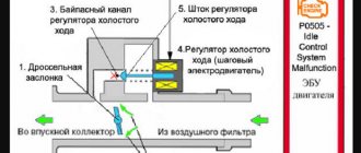
The principle of operation of a car generator
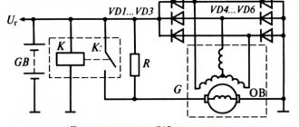
Connection diagram for the VAZ 2110-2115 generator
The alternator connection diagram includes the following components:
- Battery.
- Generator.
- Fuse block.
- Ignition.
- Dashboard.
- Rectifier block and additional diodes.
The principle of operation is quite simple: when the ignition is turned on plus through the lock, the ignition goes through the fuse box, light bulb, diode bridge and goes through a resistor to minus. When the light on the dashboard lights up, then the plus goes to the generator (to the excitation winding), then during the process of starting the engine, the pulley begins to rotate, the armature also rotates, due to electromagnetic induction, electromotive force is generated and alternating current appears.
Next, the diode passes plus into the rectifier block through a sine wave into the left arm, and minus into the right arm. Additional diodes on the light bulb cut off the negatives and only positives are obtained, then it goes to the dashboard assembly, and the diode that is there allows only the negative to pass through, as a result the light goes out and the positive then goes through the resistor and goes to the negative.
The principle of operation of a car DC generator can be explained as follows: a small direct current begins to flow through the excitation winding, which is regulated by the control unit and is maintained by it at a level of slightly more than 14 V. Most generators in a car are capable of generating at least 45 amperes. The generator operates at 3000 rpm and above - if you look at the ratio of the size of the fan belts for the pulleys, it will be two or three to one in relation to the engine frequency.
To avoid this, the plates and other parts of the generator rectifier are partially or completely covered with an insulating layer. The heat sinks are combined into a monolithic design of the rectifier unit mainly by mounting plates made of insulating material, reinforced with connecting bars.
Car generator operation
But there is no magnet in the generator; its functions are performed by the excitation winding. The states can be briefly described as follows:
- When the engine is stopped and the ignition is turned off, all vehicle systems are de-energized and no voltage is supplied to the excitation winding.
- When you turn on the ignition, constant voltage is supplied to the regulator.
- The voltage regulator allows you to stabilize the value at the same level.
- Next, the current is transmitted through the brushes and slip rings to the rotor winding.
- A magnetic field appears, but it is stationary, so no voltage is generated at the power terminal. But it is there, since this terminal is electrically connected to the positive terminal of the battery.
- As soon as you start turning the crankshaft with the starter (or even by pushing the car), the alternator rotor rotates and current is produced.
After starting the engine, the generator takes on the main load of powering electricity consumers, while the battery is charged at this time.
Generator connection diagram for VAZ 2107
The VAZ 2107 charging scheme depends on what type of generator is used. To recharge the battery on cars such as VAZ-2107, VAZ-2104, VAZ-2105, which have a carburetor engine, you will need a G-222 type generator or its equivalent with a maximum output current of 55A. In turn, VAZ-2107 cars with an injection engine use a generator 5142.3771 or its prototype, which is called a high-energy generator, with a maximum output current of 80-90A. It is also possible to install more powerful generators with an output current of up to 100A. Absolutely all types of alternating current generators have built-in rectifier units and voltage regulators; they are usually made in the same housing with brushes or are removable and mounted on the housing itself.
The VAZ 2107 charging circuit has minor differences depending on the year of manufacture of the car. The most important difference is the presence or absence of a charge indicator lamp, which is located on the instrument panel, as well as the method of connecting it and the presence or absence of a voltmeter. Such circuits are mainly used on carburetor cars, while on cars with injection engines the circuit does not change, it is identical to those cars that were manufactured previously.
Generator set designations:
- “Plus” of the power rectifier: “+”, V, 30, V+, WAT.
- “Ground”: “-”, D-, 31, B-, M, E, GRD.
- Excitation winding output: Ш, 67, DF, F, EXC, E, FLD.
- Output for connection to the serviceability lamp: D, D+, 61, L, WL, IND.
- Phase output:
,W,R,STA.
- Output of the stator winding zero point: 0, MP.
- Output of the voltage regulator for connecting it to the on-board network, usually to the “+” of the battery: B, 15, S.
- Voltage regulator output for powering it from the ignition switch: IG.
- Voltage regulator output for connecting it to the on-board computer: FR, F.
Generator circuit VAZ-2107 type 37.3701
- Accumulator battery.
- Generator.
- Voltage regulator.
- Mounting block.
- Ignition switch.
- Voltmeter.
- Battery charge indicator lamp.
When the ignition is turned on, the plus from the lock goes to fuse No. 10, and then goes to the battery charge indicator lamp relay, then goes to the contact and to the coil output. The second terminal of the coil interacts with the central terminal of the starter, where all three windings are connected. If the relay contacts close, then the control lamp lights up. When the engine starts, the generator generates current and an alternating voltage of 7V appears on the windings. Current passes through the relay coil and the armature begins to attract, and the contacts open. Generator No. 15 passes current through fuse No. 9. Similarly, the excitation winding receives power through the brush voltage generator.
Reasons for failure of the control unit on VAZ 21099, VAZ 2109, VAZ 2108
- Loose drive belt fixation;
- contamination of contacts;
- damage to rectifiers;
- brush wear;
- brushes sticking;
- short circuit;
- power supply interruption;
- The regulator does not work;
- bearing wear;
- pulley wedge;
- The fan is damaged.
Technical specifications 37.3701
| Maximum output current at 13 V and 5000 min-1, A | 55 |
| Adjustable voltage limits, V | 14,1+0,5 |
| Maximum rotor speed, min-1 | 13000 |
| Engine/generator ratio | 1:2,04 |
What does generator 37.3701 consist of: 1 – capacitor; 2 – voltage regulator assembled with brush holder; 3 – terminal block for additional diodes; 4 – insulating bushings; 5 – rectifier block; 6 – contact bolt; 7 – stator; 8 – rotor; 9 – spacer sleeve; 10 – inner bearing mounting washer; 11 – drive side cover; 12 – pulley; 13 – outer bearing mounting washer; 14 – coupling bolt; 15 – front rotor ball bearing; 16 – bushing; 17 – cover from the side of the slip rings; 18 – buffer sleeve; 19 – clamping sleeve.
But there are also some differences here. So in the first series, the VAZ 2109 generator device consists of a large number of different components:
- bushings,
- capacitor components,
- stator mechanisms,
- rotor windings,
- pulley,
- rear bearing of the rotor shaft,
- rear cover of the unit,
- fixing bolt,
A more complex design is the second series, which has many more of the above parts:
- bushing,
- brush assembly holder,
- capacitor device,
- shaft,
- coupling bolt,
- cone washer,
- fixing device for positive diode elements of the rectifying mechanism,
- fixing negative diodes and the like.
The range of the first model is often approximately 120 thousand km, but the second one is a little more, and all thanks to the slip rings, which have a smaller diameter. It all depends on the technical characteristics. As well as proper switching on of the electric generator.
Since each brand of this device is different:
Generator 37.3701: 1 – cover on the side of the slip rings; 2 – rectifier block; 3 – rectifier block valve; 4 – screw for fastening the rectifier unit; 5 – contact ring; 6 – rear ball bearing; 7 – capacitor; 8 – rotor shaft; 9 – output “30” of the generator; 10 – output “61” of the generator; 11 – voltage regulator; 12 – terminal “B” of the voltage regulator; 13 – brush; 14 – stud securing the generator to the tension bar; 15 – pulley with fan; 16 – rotor pole piece; 17 – spacer sleeve; 18 – front ball bearing; 19 – drive side cover; 20 – rotor winding; 21 – stator; 22 – stator winding; 23 – rotor pole piece; 24 – buffer sleeve; 25 – bushing; 26 – clamping sleeve.
When using 37.3701 , when turning the ignition key, voltage is connected through a special light bulb on the instrument panel, as well as resistors. When the internal combustion engine is started, the voltage goes to the excitation winding of the motors located on the rectifier block (the main voltage goes to the output of the regulator, the current does not pass through a special light bulb, as a result it does not light up).
Generator 94.3701: 1 – casing; 2 – output “B+” for connecting consumers; 3 – noise suppression capacitor 2.2 μF; 4 – common terminal of additional diodes (connected to the “D+” terminal of the voltage regulator); 5 – holder of positive diodes of the rectifier unit; 6 – holder of negative diodes of the rectifier unit; 7 – stator winding terminals; 8 – voltage regulator; 9 – brush holder; 10 – back cover; 11 – front cover; 12 – stator core; 13 – stator winding; 14 – spacer ring; 15 – washer; 16 – conical washer; 17 – pulley; 18 – nut; 19 – rotor shaft; 20 – front rotor shaft bearing; 21 – beak-shaped pole pieces of the rotor; 22 – rotor winding; 23 – bushing; 24 – tension screw; 25 – rear rotor bearing; 26 – bearing sleeve; 27 – slip rings; 28 – negative diode; 29 – positive diode; 30 – additional diode; 31 – pin “D” (common pin of additional diodes)
When using 94.3701 , approximately the same thing happens (as soon as the ignition is turned on, the voltage goes through a special light bulb to the regulator output).
It is important to constantly pay attention to ensure that everything is working properly. So the light bulb should light up immediately when you turn the key. And as soon as the internal combustion engine is started, it will turn off instantly. But if it does not immediately stop working, then the generator is faulty.
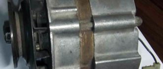
Where is the generator on the VAZ 2109
Many car enthusiasts do not know where the generator is located on the VAZ 2109, so in this section you will find information where the generator is located, see the photo
Where is the generator on the VAZ 2109
Charging diagram for VAZ with injection engines
This scheme is identical to the schemes on other VAZ models. It differs from the previous ones in the method of exciting and monitoring the serviceability of the generator. It can be carried out using a special control lamp and a voltmeter on the instrument panel. Also, through the charge lamp, the generator is initially excited at the moment it starts working. During operation, the generator operates “anonymously,” that is, excitation comes directly from pin 30. When the ignition is turned on, power through fuse No. 10 goes to the charging lamp in the instrument panel. Then it goes through the mounting block to pin 61. Three additional diodes provide power to the voltage regulator, which in turn transmits it to the excitation winding of the generator. In this case, the indicator lamp will light up. It is at that moment when the generator operates on the plates of the rectifier bridge that the voltage will be much higher than that of the battery. In this case, the control lamp will not light up, because the voltage on its side on the additional diodes will be lower than on the side of the stator winding and the diodes will close. If the control lamp lights up while the generator is running, this may mean that additional diodes are broken.
Checking the functionality of the generator
The first sign that the generator on a VAZ-2109 car has started to work incorrectly is a burning lamp on the dashboard. It shows a red battery. Therefore, there is no battery charging. First of all, check the serviceability of the voltage regulator, as well as the condition of the wires that go to it. You can check the regulator if you use a car charger and a couple of AA batteries. First, 12 Volts are supplied to it, and the lamp connected to the brushes should light up.
When a voltage above 14 Volts is applied, the lamp should not light. If it ignites in both cases or does not burn at all, then there is a malfunction of the regulator. To check the voltage generated at the generator output, use a tester. Start the engine and turn on the low beam headlights. The voltage at the battery terminals should be about 12.5-13.8 Volts. If it is less, then see if the belt is tensioned well. If everything is fine, then look for the fault deeper - in the diode rectifier.
Connection diagram for the VAZ-2101 generator
Structurally, generator 2101 consists of the following main elements:
- The rotor is a moving part that rotates from the engine crankshaft. Has an excitation winding.
- The stator is the stationary part of the generator and also has a winding.
- Front and rear covers , inside of which bearings are installed. They have eyelets for attaching to the internal combustion engine. The back cover contains a capacitor necessary to cut off the alternating current component.
- Semiconductor bridge - called a “horseshoe” for its similarity. Three pairs of semiconductor power diodes are mounted on a horseshoe-shaped base.
- A pulley on which the VAZ-2101 generator belt is placed. The belt is V-shaped (on modern cars a multi-ribbed belt is used).
- The voltage regulator is installed in the engine compartment, away from the generator. But still it must be considered part of the structure.
- The brushes are mounted inside the generator and transmit the supply voltage to the field winding (on the rotor).
Generator set price for VAZ 21099, VAZ 2109, VAZ 2108
| Catalog item | Serial number | Price | |
| A2110-80A (original) | BOSCH (9501.3801) (original) | From 3000 – 3200 | |
| 9501.3801 | FINWHALE 687-04 | 62022 / 180545 | From 3000 – 3200 |
| 9568.3749 | 922.3801 | SKL622RS | From 3000 – 3200 |
| 3701010 (HORT) | 3701024 | Contitech | From 3000 – 3200 |
| 3701971 | 3701953 | Electro 3701747 | From 3000 – 3200 |
| *prices are as of August 2022 |
Connection diagram for the VAZ-2107 generator
1 - battery; 2 - negative diode; 3 - additional diode; 4 - generator; 5 - positive diode; 6 - stator winding; 7 - voltage regulator; 8 — rotor winding; 9 — capacitor for suppressing radio interference; 10 — mounting block; 11 — battery charge indicator lamp in the instrument cluster; 12 - voltmeter; 13 — ignition relay; 14 - ignition switch.
Features of work
What might a faulty unit look like, how to remove and disassemble the generator, how is it rebuilt? If the device does not charge the injector or carburetor of a VAZ 21099 or 2109, first of all, let's look at the features of its functioning, namely the power circuit.
Generator power circuit
So, what does the scheme include:
- The VAZ 2109 generator itself.
- Negative diode.
- Additional element.
- Positive diode.
- The warning light also informs the driver that the battery is low.
- Vehicle dashboard.
- Voltmeter.
- The fuse box is installed in the engine compartment under the windshield opposite the driver's seat.
- Resistor elements installed in the same block.
- Ignition relay "nine".
- The castle itself.
- Battery
- Capacitor device.
- Winding.
- Generator voltage regulator relay installed in the engine compartment.
It should be noted that the connection diagram for the VAZ 2109 generator is relevant for all cars with front-wheel drive of the eighth line - both 2108 and 21099 (the author of the video is Semyon Pedan).
Connection diagram for the VAZ-2108 generator
The VAZ-2108 generator has a rather massive stator winding, since it uses a large cross-section wire. It is with its help that electricity is generated. The wire is wound evenly over the entire inner surface of the stator into recesses specially provided for this purpose in the magnetic core. It’s worth talking about the latter separately. The middle part, the generator stator, consists of a series of thin metal plates pressed tightly together. They are often boiled on the outside to prevent separation.
Replacing the drive belt
Different cars have differences, and the VAZ-2109 generator is no exception. If the injector is installed in the fuel supply system, then a wide belt with teeth is used. It is somewhat similar to the one used in the gas distribution system. On carburetor engines, a V-belt is used. It is narrower, but the efficiency still remains at a high level. But the requirements for the belt, both in the first and second cases, are the same. To replace the drive belt, you will need a small pry bar and a 17 mm wrench. With its help, you loosen the nut installed on the top of the generator.
Then, using a pry bar, you need to move the generator housing towards the engine block. This way you can release the tension on the belt. Now you can easily remove it. The new one is installed in place, after which you slowly move the generator housing away from the engine using a pry bar. Control the tension, because the service life of the VAZ-2109 generator depends on it. The belt should sag under a certain load at the top.
Connection diagram for the VAZ-2109 generator
- Alternator. The 37.3701 or 94.3701 series can be installed.
- Negative diode.
- Additional diode.
- Positive diode.
- Alternator warning lamp, also known as battery discharge lamp.
- Instrument cluster.
- Voltmeter.
- Relay and fuse box located in the engine compartment in the compartment between the engine and the vehicle interior.
- Additional resistors built into the fuse mounting block.
- Ignition relay.
- Egnition lock.
- Accumulator battery.
- Capacitor.
- Rotor winding.
- The voltage relay is located in the engine compartment.
The principle of operation of the power supply VAZ 21099, VAZ 2109, VAZ 2108
There are 6 coils mounted inside the generator set, the material is copper, the connection is star-shaped. The stator is a stationary structure, and the rotor rotates inside the stator. Magnetic brushes are pressed into the back of the rotor axis, and the excitation winding is wound and sealed.
After the key is turned in the ignition switch, the current from the battery creates a magnetic field, passing through the graphite brushes and copper winding. Alternating current is converted to direct current.
On the front side of the IP there are two power outputs with polarity “+” and “-”. Terminals with the appropriate polarity are connected to the battery.
To turn the generator set you will need a battery. After the battery has accumulated the spent amount of energy, the generator distributes the excess to other power sources. Thus, the size of the on-board network is maintained within an acceptable range.
Connection diagram for the VAZ-2110 generator
On VAZ-2110, 2111 and 2112 cars, a 94.3701 generator was installed with a maximum output current of 80 Amperes and a voltage = 13.2–14.7 Volts.
Here is a breakdown of the connection diagram for the generator on the ten :
- Battery 12V;
- generator 94.3701;
- mounting block;
- egnition lock;
- battery charge indicator lamp in the instrument cluster
Why is a generator needed?
It is needed to power the on-board network when the engine is running. When stopped, the entire network is powered by a battery. If you yourself replaced the VAZ-2108 generator or any other car, you saw that it has one power terminal. Several wires are connected to it:
- The thickest one connects the generator to the positive terminal of the battery. It is through this wire that the battery is charged. Please note that there are no fuses on it. Therefore, during any manipulations with the generator, it is necessary to de-energize the on-board network.
- A thin short wire going to the voltage regulator is necessary to power the excitation winding.
- It is rare, but it happens that additional equipment is connected to this output of the generator.
The cars use a rather old but proven design of the VAZ-2108 generator. The carburetor is used in the fuel injection system. On injection cars, fuel injectors and ignition coils are powered from the power output of the generator. All other consumers take power from the positive terminal of the battery.
Technical characteristics of generator 37.3701
— The magnitude of the delivered current (at 6000 rpm-1 and voltage 13 V) – 55 A
— Voltage value – 13.6 – 14.6 V
— The direction of rotation of the rotor is right
— Maximum rotor speed – 13000 rpm-1
— Gear ratio engine/generator 1/2.04
How to check the generator yourself
How to check a VAZ generator using the example of model 2109. Generator type 94.3701 alternating current, three-phase, with a built-in rectifier unit and an electronic voltage regulator, right-hand rotation.
Generator connection diagram . The voltage to excite the generator when the ignition is turned on is supplied to terminal “D+” of the regulator (terminal “D” of the generator) through indicator lamp 4 located in the instrument cluster. After starting the engine, the excitation winding is powered by three additional diodes installed on the generator rectifier block. The operation of the generator is controlled by a warning lamp in the instrument cluster. When the ignition is turned on, the lamp should be on, and after starting the engine, it should go out if the generator is working. If the lamp is brightly lit or glows half-lit, it indicates a malfunction.
The “minus” of the battery should always be connected to ground, and the “plus” should always be connected to the “B+” terminal of the generator. Failure to turn the battery back on will immediately cause increased current through the generator valves and damage them.
It is not allowed to operate the generator with the battery disconnected. This will cause short-term overvoltages to occur at the “B+” terminal of the generator, which can damage the generator voltage regulator and electronic devices in the vehicle’s on-board network.
It is prohibited to check the functionality of the generator “for spark” even by briefly connecting the “B+” terminal of the generator to ground. In this case, significant current flows through the valves and they are damaged.
Rotor and stator windings
First, it’s worth talking about what a stator winding is. It is from it that the voltage is removed to power the vehicle’s on-board network and charge the battery. On a VAZ-2109 car, the generator is very similar to an AC asynchronous motor. However, if you make minor changes to the design, the generator can also be used as an electric drive. Three windings on the rotor, each with a beginning and an end. The ends are connected at a common point. This connection is called a “star”.
As for the rotor winding, it is much simpler. There are no extra taps, the copper wire is wound in bulk on the rotor. The ends of the winding are connected to contacts that are located on the back of the rotor. Particular attention, of course, is paid to the magnetic circuit, due to which the field is formed around the coil. When rotating, the magnetic field induces a certain potential in the stator windings. Actually, this is what the entire operation of the generator is based on. But there are many smaller nuances that we can talk about for as long as we like.
Replacement and removal of the electric generator
The generator on a VAZ car is removed either for complete replacement in case of failure or to carry out repair work to replace faulty parts. To perform dismantling, prepare a standard set of tools; it is advisable to drive the car into the inspection hole.
- Disconnect the battery.
- Remove the protective rubber cap from terminal “30” and unscrew the nut and remove it from the wire stud.
- Disconnect the block with wires from the generator connector.
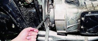
- We loosen the tightening of the generator to the adjusting bar, then lift it all the way up to the cylinder block and remove the belt from the pulleys.
- Completely unscrew the bolt securing the adjusting bar to the cylinder block, then from the bottom of the car unscrew the 2 bolts securing the lower bracket to the block and remove the generator, pulling it out of the engine compartment.
The practical part is removing the generator, disassembling it, repairing it and reinstalling it.
Due to the fact that the generator is located under the hood of the car, it is necessary to turn off the engine, turn the steering wheel to the right all the way and open the hood. The electric generator on VAZ 2108 - 15 cars is installed in front of the engine, in the lower left corner of the engine compartment, between the engine and the cooling radiator.
Before dismantling the generator, it is necessary to disconnect the ground from the battery, i.e. negative contact.
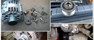
Replacing VAZ generator brushes
Before removing the generator itself, in order not to do unnecessary work, we remove the charging relay from the generator housing and check the production of the generator brushes. The charging relay is installed in the rear of the generator housing, and is attached to it with two bolts. To unscrew them you will need a Phillips screwdriver. When unscrewing the bolts, be careful not to drop them on the crankcase guard, otherwise getting them out of there will be one big problem.
To remove the relay, you need to disconnect the wire, the “female” contact. After removing the charging relay and visually inspecting the brushes, we decide to purchase a new generator voltage regulator relay or reinstall the dismantled one, depending on the wear of the brushes. For their normal operation, a brush length of at least 4 cm is required. Now we proceed directly to removing the electric generator from the engine.
- We disconnect the wires from the generator - as a rule, they are red and consist of two groups of wires, red. One group consists of two wires and is attached with a nut to a bolt on the rear wall of the generator. The other group consists of one wire and is connected to the generator terminal via a male-female contact, also on the rear wall of the generator.
- To remove the generator from the engine, you need to unscrew two nuts and one bolt in the following sequence: unscrew the nut attached to the generator belt tensioner bar (at the top of the generator), unscrew the bolt securing the tensioner bar to the engine block and remove it. The last step is to unscrew the nut from the bolt securing the generator bracket to the engine block.
- The generator mounting bracket is located at the bottom of the engine block, directly below the generator. After unscrewing this nut, you need to remove the generator belt from the generator pulley itself.
- The generator mounting bolt should be pushed to the left, out of the bracket, until it stops against the body shell or the generator’s mud protection.
- On the right wheel side, you need to unscrew the two screws that secure the dust protection of the generator to the car body.
- If the generator mounting bolt still rests against any body parts, you should press on the engine with one hand, and at the same time pull out the bolt with the other hand.
Now your generator is completely disconnected from the engine, and you can begin to disassemble and repair it.
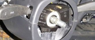
Removing the generator pulley
To do this, we stop it from turning with a screwdriver and unscrew the nut securing it with a 19 mm spanner. The tightening torque is large, so it is better to use a wrench with a long handle.
Removing generator pulley 37.3701 for VAZ 2108, 2109, 21099 cars
Then we remove the following parts: nut, washer, pulley with impeller, segment key.
Separate the halves of the generator housing
First, we mark their relative positions (by placing marks on both parts). Using a 10 mm wrench (it’s more convenient to use a socket or socket wrench), unscrew the four nuts of the coupling bolts (there are engraving washers under the nuts).
Pull out the bolts. Remove the front part of the generator. Remove the rotor from the back of the generator. If it cannot be removed, you can tap it with a soft metal drift through the window under the voltage regulator, or by screwing a nut onto the thread of the shaft and holding it in a vice, with a sharp upward movement, pull the back cover into the shaft. The bearing remains on the rotor shaft. If necessary, we dismantle it with a puller and press on a new one (See “Replacing generator bearings”).
Disconnect the stator
Using an 8 mm wrench (it’s more convenient to use a socket or socket wrench), unscrew the three nuts securing the stator terminals to the diode bridge. We remove it from the back cover of the generator by prying it with a slotted screwdriver or hitting it with a hammer.
When is it time to repair a generator?
1. Any instrument cluster has a battery charge indicator (indicated by a red arrow, using the example of an instrument cluster from a high panel). When the generator stops supplying charge to the battery, this indicator lights up. When the ignition is turned on, it should light up, but when the car starts, it must go out. Otherwise, the generator does not produce current and needs to be inspected. It happens that the battery runs out quickly, and the indicator lamp does not light up at all. In fact, you can’t trust it 100%; sometimes the generator produces a very weak current, insufficient for a light bulb. This situation leads to the fact that literally in 1 week the battery is completely drained and you have to put it on charge. We recommend periodically checking a working battery.
2. You will need a multi-meter with the voltmeter function enabled. Measure the readings given by the generator to the battery (the procedure is demonstrated in detail in the video below). After you start the car, the voltage at the terminal will most likely be about 12-13 Volts and will gradually increase. Don't have a voltmeter? There is an alternative way to check, but it causes damage to the diode bridge (we do not recommend using this method on fuel-injected cars; it is better to stock up on a multi-meter):
- start the engine and let it run for approximately 2 minutes;
- apply gas and pull out the choke so that the engine reaches about 2 thousand revolutions;
- Disconnect the negative terminal from the battery.
If the car works, everything is fine with the generator, put the terminal back. The car stalled - the generator has become unusable and needs to be replaced or repaired. But! It happens that the generator gives a charge, but it is too weak (around 12 Volts), which is why the battery quickly runs out (the car will not stall after removing the terminal from the battery, so this method does not always work).
Useful tips
The VAZ 2109 wiring diagram is necessary without any intention of making changes to the car’s structure, because during operation the wiring is subject to:
- Temperature effects - both climate changes and daily heating and cooling cycles;
- Mechanical loads - wiring runs throughout the entire car body, exposed to components and mechanisms, passengers and transported goods
Accordingly, the owner is required to perform a preventive inspection of the standard wiring in order to identify insulation violations and mechanical damage. Timely detection of a malfunction will allow you to quickly correct and prevent more significant failures in the operation of the vehicle’s electronic devices.
Conclusions: we hope that the issues covered in this article will protect you from thoughtless intervention in the electrical circuit of your car. And if you need to replace the standard wiring, you will do it in accordance with the manufacturer’s recommendations.
1200 rub. for the photo report
We pay for photo reports on car repairs. Earnings from 10,000 rubles/month.
Write:
The most basic function of the generator is to charge the battery and power the electrical equipment of the engine.
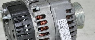
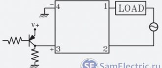
A generator is a mechanism that converts mechanical energy into electrical energy. The generator has a shaft on which a pulley is mounted, through which it receives rotation from the engine crankshaft.
Interactive image of the generator circuit. Works on mouseover
A car generator is used to power electrical consumers, such as the ignition system, on-board computer, car lighting, diagnostic system, and it is also possible to charge a car battery. The power of a passenger car generator is approximately 1 kW. Car generators are quite reliable in operation because they ensure uninterrupted operation of many devices in the car, and therefore the requirements for them are appropriate.