Car : VAZ-2112. Asks : Smirnov Ivan. The essence of the question : I can’t find the fuel pump relay for the VAZ-2112?
Good afternoon, my gas pump has stopped pumping. When I turn the key, nothing happens. I think there is something wrong with the electrical system. Can you please tell me how to find the fuel pump relay?
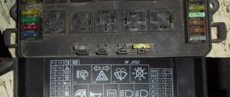
Pinout BN VAZ 2113, 2114, 2115
— block headlights; — gearmotors for headlight cleaners*; - fog lights*; — ambient temperature sensor; - sound signals; — engine compartment lamp switch; — electric motor of the engine cooling system fan; — generator; — low oil level indicator sensor; — washer fluid level sensor; — front brake pad wear sensor; — wire tips connected to the common windshield washer pump**; — windshield washer pump; — headlight washer pump*; — wire ends for connecting to the rear window washer pump on VAZ-2113 and VAZ-2114 cars; — low oil pressure indicator sensor; — engine compartment lighting lamp; — wire lug for connecting to the wiring harness of the engine control system; — gear motor for windshield wiper; — starter; — a block connected to the wiring harness of the ignition system on carburetor cars; — coolant temperature indicator sensor; — reversing light switch; — low brake fluid level indicator sensor; - accumulator battery; — low coolant level indicator sensor; — relay for turning on fog lights; - mounting block; — brake light switch; — plug socket for a portable lamp; — hydrocorrector scale illumination lamp; — switch for the parking brake indicator lamp; — block for connecting a backlight lamp; — switch for instrument lighting lamps; - Understeering's shifter; - hazard warning switch; — front seat heating element relay; — ignition switch; — rear fog light circuit fuse; - fuse for the front seat heating elements; — door lock circuit fuse; — front ashtray illumination lamp; — ignition relay; - cigarette lighter; — glove box lighting lamp; — switch for the glove compartment lighting lamp; — heater fan electric motor; — additional resistor for the heater electric motor; — heater fan switch; - heater switch illumination lamp; — lamp for illuminating the heater levers; — gear motors for electric windows of the front doors; — power window switch for the right front door (located in the right door); — gear motors for locking front door locks; — wires for connecting to the right front speaker; — gearmotors for locking rear doors; — wires for connecting to the right rear speaker; — door lock control unit; — wires for connection to radio equipment; — headlight cleaner switch*; — rear window heating element switch; — relay for turning on the rear fog lights; — block for connection to the heating element of the right front seat; — rear fog light switch; — switch for the heating element of the right front seat; — fog light switch*; — switch for external lighting lamps; — left front seat heating element switch; — block for connection to the heating element of the left front seat; — wires for connecting to the left front speaker; — power window switch for the left front door (located in the left door); — power window switch for the right front door (located in the left door); — wires for connecting to the left rear speaker; — side direction indicators; — courtesy light switches on the front door pillars; — courtesy light switches on the rear door pillars; - lampshade; — ceiling lamp for individual interior lighting; — block for connecting to the wiring harness of the electric fuel pump; — trunk light switch; — instrument cluster; — trunk lighting lamp; — display unit of the on-board control system; - trip computer*; — block for connecting the wiring harness of the engine control system; — rear exterior lights; — rear interior lights; — pads for connecting to the rear window heating element; — license plate lights; — additional brake signal located on the spoiler.
Fuel check valve
The electric fuel pump of the VAZ “Ten” has good performance, but it creates too much pressure in the fuel system. In order to bring the pressure back to normal, a VAZ 2110 fuel pump valve is built into the fuel line; it is located in the “outlet” fitting of the BN housing. On the “tens”, a pressure regulator is also installed, which is located behind the fuel rail.
A valve malfunction involves a ball sticking in the open position, and the fuel pressure in the system may drop to zero. If such a problem occurs, the car is very difficult to start, since all the gasoline from the fuel lines goes back into the gas tank when the ignition is turned off. Is it possible to somehow repair the valve?
Drivers of 2110 cars claim that you can try knocking on the fitting in the BN flask so that the shut-off ball falls into place. If the malfunction cannot be eliminated in this way, the electric fuel pump bulb must be replaced, since this housing itself is non-separable.
Fuel pump relay VAZ 2110 injector 8 valves where is it located
Dear visitors of the site “Everything about cars”! We will be very grateful for your comments on the video clip “Where is the fuel pump relay for VAZ 2110 injector 8 valves?”, registration is not required for this. We also ask you to let us know if you have any problems playing the video.
thank you for the detailed video, the question has arisen about replacing the fuel pump mesh, and as a young driver it was very helpful
08/12/2017 — 21:05 Smouk65
Tell me what is the button to the right of the keys that blinks red?
05.08.2017 — 05:25 oipm pmpm
please tell me, my pump is humming, will replacing the mesh help? or is it better to change the pump?
03.08.2017 — 20:20 Slava Kazak
Or you can change the float and track separately, otherwise on my top ten it’s like you can’t start a car, so the device shows different fuel levels.
07/18/2017 — 04:25 SteFan
I accidentally poured about 1.5 liters of water into the tank, what should I do? The fuel pump is not working, how to drain the water.
07/12/2017 — 16:22 Boris Grishin
Well done. Everything is clearly intelligible.
07/11/2017 — 04:13 Alexander Suvorov
Thanks for the video Please make a video about replacing the fuel pump
06.23.2017 — 19:19 Ivan Dadykin
Is this an old-style fuel module? I watched another video on replacement, the modules are slightly different.
06/09/2017 — 20:45 MIKHAIL TROFIMOV
During disassembly, I tore off the thread on the fuel pipe, or rather the first two turns. When reassembling in the reverse order, the fuel pipe does not tighten completely. I started the car, the fuel pump pumps gasoline from under the tube, nothing oozes. What do you recommend if you don’t change the handset?
06.06.2017 — 07:43 malytino
Great educational video. Well done author. It may really be useful for novice drivers.
05/09/2017 — 07:38 taksist komandir
Instead of a rubber seal, you can wind a thread, it holds well and does not leak
04/28/2017 — 13:13 Sergey Sergeev
03/30/2017 — 11:02 Yuri Zotov
everything is clear and correct remark about the battery and ring gaskets, pressure relief
03/28/2017 — 20:08 Hicks Aliens
Damn the grid is dirty, what do you fill the tank with, brother?
04.03.2017 — 20:43 Soslan Bekoev
Good afternoon. Please tell me. I have a problem with the Kalina 8 valve. When the temperature rises above 90, the engine will not start until the pressure drops. Diagnostics showed nothing. The valves have been adjusted. Traction and engine operation without problems. but only up to 90 degrees
02/27/2017 — 21:38 Evgesha
Please tell me. What kind of O-rings should I buy from the store for tubes? In our stores they don’t know what sizes they are.
02/18/2017 — 15:39 Long Project
Thank you very much for the video. I have trouble starting when it sits, apparently the pressure will drop. If I turn it off and start it, everything is fine, I’ll try to change the grid, because gasoline is such a waste right now
01/24/2017 — 01:23 BEST MOVIE IN HD
Well done. explained everything perfectly
01/08/2017 — 05:39 craniosex Nekroman
Good evening, due to poor eyesight, before I took out the fuel pump, I broke the same long tube that you unscrewed with the 17th key. What should I do now?
01.01.2017 — 10:20 Ivan Rysev
good evening, but I couldn’t put on the container that is located under the fuel pump, is there any danger?
Signs of a fuel pump failure
A faulty fuel pump is quite easy to identify, since it is characterized by characteristic signs of failure. For example: while driving, the car suddenly stalls - after turning it on again, the engine begins to make uncharacteristic sounds, while the starter does not stop turning. After the car starts up, the picture repeats itself - the fourteenth engine stalls again. It is also possible that the car starts every once in a while - problems usually arise after sitting at neutral speed.
Let's determine the most typical signs of a fuel pump malfunction:
- The engine refuses to start. Of course, there can be many reasons for this problem - the same spark plugs, or the ECU, but the possibility of a fuel pump malfunction is also worth taking into account;
- The pressure level in the fuel relay differs from normal values;
- The motor is tripping. As a rule, if the fuel pump does not pump as it should, the engine begins to twitch quite noticeably because gasoline is not burned properly in the working cylinders;
- The engine growls at low speeds. One of the most truthful signs, which indicates either an immediate breakdown of the pump, or that the low-purity filter is clogged and the mesh needs to be replaced.
There are quite a lot of possible breakdowns that could cause the fuel pump to fail. The following parts of the unit design can present an unexpected surprise: fuse, fuel pump relay, ground, electric motor, contact system. Let's look at each of them separately.
Pressure level
In order to get most of the picture of what is happening, it is enough to measure the pressure in the fuel rail. For this, it is necessary to use a pressure gauge that has a small measurement range (preferably up to 7 atmospheres), since devices with a large range can produce significant inaccuracies.
Rail pressure measurement
Under the hood of the fourteenth there is a pressure fitting; unscrew its cap and connect the pressure gauge to it.
Normal indicators should be as follows:
- When the engine is idling – 2.5 kPa;
- At the moment of ignition - 3 kPa;
- With a pinched drain hose – 7 kPa;
- When gaining speed - 2.5-3 kPa.
If the pressure gauge needle does not move when the ignition is turned on, then the gasoline pressure regulator is most likely broken. When there is no change as the speed increases, the fuel pump itself has failed, but if the needle moves very slowly, which indicates that the pump is pumping, but poorly, the fuel pump screen is clogged.
How to test wiring with a multimeter
If the fuel pump does not work, do not rush to change it - perhaps the problem is in poor-quality wiring. There are 3 wires connected to the pump: to the gasoline level sensor, and positive and negative to power the motor.
No special tools are required to check the wiring - a regular 12-volt light bulb is enough. We connect the light bulb to the negative and positive wires of the pump, and turn on the car’s ignition - if the light blinks, then everything is fine with the wiring.
Fuel pump motor
When you have determined that the external wiring of the fuel pump is normal, you need to move on to checking the motor. This is done with the same light bulb, the wires of which are connected to the external terminals of the motor. If the light comes on when you turn on the ignition, then you need to change the motor.
Fuel pump ground and relay
In the fourteenth, the mass of the fuel pump is fixed under the dashboard, next to the handbrake lever, during use of which the mass can be touched and shifted from its normal position. To fix this, remove the plastic around the handbrake, clean the ground contacts and reattach it.
Next to the ground there is a VAZ 2114 fuel pump relay. The relay is necessary so that during ignition the required pressure level is immediately created in the system.
A few words about where the fuel pump relay is located: after removing the plastic around the handbrake, you will immediately find 3 different relays - one of them is from the fuel pump.
GU or generator
The generator in any automotive electrical circuit performs the dominant functions. The normal functioning and operation of the machine depends on it. Reliable PG is installed in all foreign cars and models of the domestic automobile industry.
For example, a GU is placed on the “six”, the charge of which satisfies the need for electricity of any standard component. If you do not overload the generating device of the “six”, then the car is capable of driving many, many more kilometers
However, it is important to carry out preventive procedures in a timely manner - monitor the belt tension and the condition of the brushes
The GU is connected according to the classical scheme. Using the VAZ 2106 generator as an example, let’s consider its functioning. This GU is marked as G-221. It is an AC synchronous electric machine with ELMG excitation. A VB (rectifier) with 6 diodes is built inside the GU.
| 1 | generator rotor winding |
| 2 | generator |
| 3 | generator stator winding |
| 4 | generator rectifier |
| 5 | accumulator battery |
| 6 | ignition switch |
| 7 | battery charge indicator lamp |
| 8 | battery warning light relay |
| 9 | fuse box VAZ -2106 |
| 10 | throttle |
| 11 | temperature compensation resistor |
| 12 | additional resistors |
| 13 | voltage regulator |
A simple and understandable scheme that does not require any subtleties or specific knowledge. On the “six” the PG is located on the engine on the right. It is attached to the tension bar with a nut and to the bracket with its claws.
As you can see, the diagram shows an external regulator. It is marked with the number 13. The generator is indicated with the number 2, the fuse box is indicated with the number 9.
Separately, I would like to consider the relay, which plays an important role in the “six” generator circuit. First of all, it serves to provide information to the driver about the charging status. As is known, it is created by a generating device.
The relay is made on the same principle as all devices that function according to the same properties. The connection is made to terminal 30 of the generator. A separate wire goes through the fuses to the 3Z (lock).
- Why does the battery light on the instrument panel light up?
The action of the relay boils down to the following: as soon as the voltage of the BS decreases (falls below the 12-volt value), the relay contacts open, the indicator is activated, giving a sign to the driver.
To better understand the connection diagram, it is recommended that you also familiarize yourself with the principles of battery charging:
- as soon as the key is turned into the 3Z, an electric pulse is supplied to the relay regulator through the fuse (pin 15);
- in the regulator the voltage is transformed and goes further to the positive brush of the GU;
- then, through the brush, the voltage goes to the excitation winding of the GU;
- then - to the negative brush, through which it is brought to ground.
After the relay is activated or after the normal voltage value has been reached in the BS, the GU begins to generate current with the required value. The indicator lamp goes out, and the circuit starts working in factory mode. But when the total voltage drops, the current is not enough, and the contacts open, which leads to the discharge lamp burning.
The constant switching on of the charge indicator lamp indicates that the gene is not working properly. This happens for various reasons. First, you should check the fuses: if they are active, then both relays deserve attention: the regulator and the charger. If they are also in order, then faults must be looked for in the generating device itself.
Before proceeding with replacing the relay, it is recommended to carefully check the functioning of the regulator. The car starts, the speed is kept within the range of 2500-3000 rpm. After this, you need to turn off all current consumers, except the ignition. Then you need to measure the voltage at the battery terminals.
Charging may disappear in the following cases:
- If the generator brushes are worn out.
- In case of malfunction of the generating device.
- If the charging relay is faulty.
- If the rectifier unit (diode bridge) fails.
Thus, installing an external relay-regulator instead of a built-in one will bring a lot of benefits. The fact is that modern charging systems have much more power. Thus, modern memory systems are much more complex than old-style systems.
- Absolutely legal (Article 12.2);
- Hides from photo and video recording;
- Suitable for all cars;
- Works through the cigarette lighter connector;
- Does not cause interference to radios and cell phones.
The VAZ 2106 voltage regulator relay ensures the normal functioning of important vehicle mechanisms and devices. In particular, the adequate operation of the car’s ignition system and its generator, as well as the condition of the battery, depend on it.
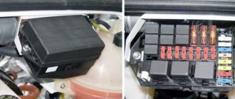
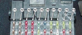
Where is the fuse and fuel pump relay on the VAZ 2110
It’s worth saying right away that the fuse and relay for the VAZ 2110 injector fuel pump are located in the same place. They are both located in the center console on the passenger side below. The main task of a relay in an electrical circuit is to close and open a circuit. Thanks to this, the circuit is protected from high inrush current.
| F1 - 5A | License plate lamps. Instrument lighting lamps. Side light indicator lamp. Trunk light. Left side marker lamps. |
| F2 - 7.5A | Left headlight (low beam). |
| F3 - 10A | Left headlight (high beam). |
| F4 - 10A | Right fog lamp. |
| F5 - 30A | Electric door window motors. |
| F6 - 15A | Portable lamp. |
| F7 - 20A | Engine cooling fan electric motor. Sound signal. |
| F8 - 20A | Rear window heating element. Relay (contacts) for turning on the heated rear window. |
| F9 - 20A | Recirculation valve. Windshield and headlight cleaners and washers. Relay (coil) for switching on the heated rear window. |
| F10 - 20A | Spare. |
| F11 - 5A | Starboard side marker lamps. |
| F12 - 7.5A | Right headlight (low beam). |
| F13 - 10A | Right headlight (high beam). Indicator lamp for turning on the high beam. |
| F14 - 10A | Left fog lamp. |
| F15 - 20A | Electrically heated seats. Locking the trunk lock. |
| F16 - 10A | Relay-breaker for direction indicators and hazard warning lights (in hazard warning mode). Hazard warning lamp. |
| F17 - 7.5A | Interior lighting lamp. Individual backlight lamp. Ignition switch illumination lamp. Brake light bulbs. Clock (or trip computer). |
| F18 - 25A | Glove box lighting lamp. Heater controller. Cigarette lighter. |
| F19 - 10A | Locking door locks. Relay for monitoring the health of brake light lamps and side lights. Direction indicators with warning lamps. Reversing lamps. Generator excitation winding. On-board control system display unit. Instrument cluster. Clock (or trip computer). |
| F20 - 7.5A | Rear fog lamps. |
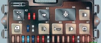
| K1 | relay for monitoring the health of light bulbs; |
| K2 | front wiper relay; |
| K3 | repeater and alarm relay interrupter; |
| K4 | low beam relay; |
| K5 | high beam relay; |
| K6 | additional relay; |
| K7 | rear window heating relay; |
| K8 | backup relay |
A similar type of relay is installed on the fuel pump, protecting the circuit when the engine starts. It consists of a plastic housing that houses an electromagnetic coil with a core. The incoming voltage allows the core contacts to close. The operating current of the relay is 30 Amperes.
Where is the fuel pump relay located on a VAZ 2110?
People often wonder where the fuel pump relay is located on a VAZ 2110; this photo will help you answer this question ↓
Where is the fuel pump relay located on a VAZ 2110?
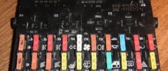
Location of the relay and fuse for the fuel pump VAZ 2110 injector
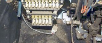
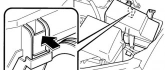
If during repairs or diagnostics, the fault indicates a relay and fuse, then they must be removed and replaced with new parts. You should prepare a Phillips screwdriver and position yourself on the passenger side. At the bottom of the center console there is a cover secured with two screws. You need to unscrew them. It is there that the panel is located where the VAZ 2110 injector fuel pump relay is located and where the fuse for the VAZ 2110 fuel pump is located.
Rice. 2 Removing the side cover
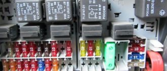
After removing the protective cover, access to the power fuses and relays of the car appears. The required parts responsible for the operation of the fuel pump are marked with numbers 5 and 2 in the center of the photograph.
Fig.3 Power fuses and relays
Why does the VAZ 2110 fuel pump fuse blow out?
Fuse failure is a fairly common occurrence. Burnout indicates one thing - there is a short circuit in the fuel pump power system. In this case, you can change the fuse, drive away for several days without problems, and the situation will repeat again. So it is necessary to look for the reason.
The most common culprits are:
- the wiring harness above the exhaust manifold melted;
- wires under the carpet are damaged or melted;
- interturn short circuit in the pump motor;
- The positive wire going to the pump is damaged (current leakage to ground).
To identify the cause, you should disconnect the power supply from the fuel pump and turn on the ignition. If the fuse is blown, then the problem is in the wiring. Remained intact - short circuit in the electric motor. In the first case, you have to inspect the entire harness, looking for contact of the “plus” with the ground. As a rule, this is a gray wire running from the relay to the tank. The harness runs along the central tunnel, and not from the left threshold.
Technical specifications
If the old generator fails, many motorists wonder which generator they should now replace the old one with.
There is no need to invent anything here. The most correct solution is to install the same generator as before, or a more powerful one.
Today, the VAZ 2110 provides for the use of three types of power supply devices:
- Katek 5102.3771. The generator produces 80 Ampere power and its voltage is approximately 14V.
- Katek 94.3701. This is a device with the same parameters. They are not seriously different.
- Catek 120 amp. A generator that is more adapted to modern realities, when in addition to standard electrical equipment, motorists install many additional devices.
If you have a powerful audio system in your car, you use an electric pump powered by the car, as well as a number of other additional consumers, it is recommended to install a 120-amp unit instead of a standard 80-amp generator.
If we take into account the size of the devices, then we can distinguish between ordinary and compact ones. They have a certain difference in design
To be specific, the differences are in the following components:
- Brackets;
- Anchor;
- Excitation wire;
- Drive pulley;
- Number of mounting bolts.
But in reality this does not play a special role. After all, the structure of all generators used for the VAZ 2110 is the same. Therefore, let's look at the circuit and structure of this unit.
| Element | Functions |
| He's an anchor. It is a rotating element of the generator, which creates a magnetic field due to the excitation winding located on the shaft. The field wire receives power from the slip rings. They are mounted on the same shaft. There was also room for a drive pulley, field winding wire, bearing assembly and fan impeller. There may be 1-2 last ones | |
| This is a stationary three-phase element that includes three windings. They provide the creation of alternating current. The windings are connected to each other using a triangle or star | |
| A lightweight non-magnetic aluminum alloy is most often used to make the generator housing. The body looks like a pair of covers connected by a bolt. The front cover is located near the drive pulley, and the rear cover is located on the side of the slip rings. Each connecting bolt must be tightened. To disassemble the housing, simply unscrew the mounting bolts. | |
| The upper mounting bracket for the generator uses two bolts, while the lower bracket is predominantly mounted on one bolt. In some cases there are two. It is not recommended to modify the brackets, since the factory one performs important functions. The purpose of the brackets is to hold the generator. It is recommended to monitor the condition of the brackets as they are subject to wear and breakage | |
| Brush unit | It consists of a pair of graphite brushes, springs that press the brushes, as well as a brush holder |
| Brush holder assembly and voltage wires | This design is typical for modern Katek generators. Therefore, if the regulator fails, you will have to replace the entire assembly |
| Rectifier block | Equipped with 6 diodes, it is responsible for converting alternating current into direct current. It is direct current that is required for the operation of all auto equipment. This element charges the battery, among other functions. |
| Belt drive transmission | The belt drive allows you to increase the speed at which the crankshaft rotates. If the pulley has a small diameter, then the V-belt will wear out faster. Therefore, for small driven pulleys it is recommended to use a poly-V-ribbed drive. It is most often found in modern generators |
The presented device is relevant for all generators used on the VAZ 2110, regardless of their power - 80-120 Amperes.
Margin of safety
If we take into account the standard Katek generator, which is installed on domestic dozens, then its resource is enough for about 10 years of operation or 140 thousand kilometers. The specified safety margin of the device can only be relied upon if it is handled properly
The specified safety margin of the device can only be relied upon if it is handled properly.
Many people fear that a powerful 120 A generator can negatively affect the condition of the battery. In practice, nothing like this happens. Moreover, installing a more powerful unit is recommended if you plan to install an impressive audio system or video equipment on the car.
If everything has been checked, but the fuel pump does not work - article numbers
In general, the pump article number for VAZ-2112 engines looks like this: 21102-1139009-XX. Instead of the letters XX there are numbers, for example 02 or 03. They indicate the manufacturer. So, modules from different factories are not interchangeable! The resistance of the FLS resistor is different in them. However, when replacing the FLS sensor, you can borrow it from the “old” module. That's what they usually do.
Until April 2002, article numbers of the type 2112-1139009 were used.
Almost every module available for purchase contains a built-in pressure regulator. There are also exceptions - KSZC-A243, for example. The meaning is as follows:
- All internal combustion engines with a volume of 1.5 liters are equipped with a ramp with an “external” regulator (2112-1160010);
- The 21124 or 21114 motor requires a built-in regulator.
In conjunction with 1.5 liter engines, you can use any module – both with and without a built-in regulator.
Designations of analogues
- 21102-062213.0XX – instead of the letters XX there will be a plant designation (07, 13, etc.);
- KSZC-A233 or A243 – KSZC brand. There is no pressure regulator.
What is a relay for?
Above we talked about the microcontroller system. It is worth noting that the output of the ECU does not allow direct connection of a powerful load. And the fuel pump, which is based on a DC motor, has quite a lot of power. And when it is turned on, a significant current consumption occurs. But if you turn on the VAZ 2110 fuel pump relay coil from the control unit, the injector will continue to operate in the same mode, and no excess current consumption will be observed.
Therefore, we conclude: a relay is a buffer cascade between the electronic control unit and the current consumer. However, most relays have precisely this purpose - they allow a very weak current to flow in the control circuit. In this case, the entire electrical system of the car is divided into two parts:
- Low-current control circuits.
- Power cables (connecting optics, fluid and fuel pumps, power windows).
The VAZ 2110 fuel pump relay is located on the right side, opposite the front passenger seat. There is an additional block designed for installing some elements of electrical equipment. It is quite possible that such a simple solution was caused by the reluctance of the designers to use other fuse blocks that would be very different from those installed on carburetor engines.
The fuel pump relay does not turn on.
If the fuel pump does not work, then first of all you need to check the attraction of the main relay and the fuel pump relay. If the main relay does not click, then it is necessary to check its switching circuit and its serviceability. How to do this is described in the article the main relay does not turn on,
In the case when the main relay turns on, but the fuel pump relay does not, it is necessary to check the power at pins 85 and 86. When using a test lamp, its current consumption should not exceed 0.25A, otherwise damage to the controller may occur. If the control lamp does not light up on any terminal, then the relay is not receiving power. This may be caused by a blown fuse or a broken power cord.
In the case when the lamp burns brightly on one terminal, and at half-glow on the second, and the relay may be activated, you should remove the relay from the socket and connect terminals 85 and 86 with a test lamp. When the ignition is turned on, the control lamp should light up and go out after approximately 20 - 30 seconds. If the lamp lights up and there is poor contact in the connection between the block and the fuel pump relay. If the lamp does not light up, there may be a break in the wire connecting the relay to the controller or the controller itself may be faulty.
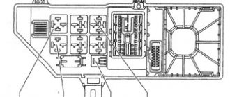
Additional block
It is located under the center console and is covered with a lid. One part is accessible from the right side.
Scheme
Designation
The other part is on the left side of the console:
Scheme
Decoding
On our channel we also prepared a video on this publication. Watch and subscribe.
Do you know how to make the material better? Write in the comments.
Source
Malfunctions of the electric fuel pump 2110
If the pump stops working, there may be several reasons for the malfunction:
- electrical wiring is damaged;
- fuse burned out;
- the relay stopped working;
- BN motor burned out;
- The engine control unit has failed.
When a driver in a car with a VAZ 2110-12 injection engine turns on the ignition, the electric motor starts working - a characteristic buzzing sound is heard. If no sounds are noted, it means that the BN is not pumping fuel.
The easiest way is to check the electric fuel pump fuse, which is located almost in the same place as the relay, located to the left of the RB.
If the fuse is blown, it must be replaced. It often happens that when replacing a fuse, it immediately blows. The main reasons for the malfunction of this phenomenon:
- the fuel pump itself “shorts”;
- There is a short circuit in the electrical wiring.
Another characteristic malfunction of the electric fuel pump is that fuel is pumped, but the operation is accompanied by loud noise. A noisy fuel pump is a sure sign that this device will not “live” for long and will soon fail.
On-board computer
Fuse element F17 or F19 is responsible for it. In the first case, the power is 7.5 A, and in the second - 10 A.
Specialization: Graduated from the State Automobile University, worked for 20 years at GAZ-56, now I drive a Zhiguli.
p, blockquote 1,0,0,0,0 —>
p, blockquote 2,0,0,0,0 —>
The purpose of fuses and relays in your VAZ 2110 (2111 / 2112) relay may differ from those presented and depend on the year of manufacture. The current purpose can be printed on the block itself.
Checking the fuel pump relay yourself
At the beginning of the test, you need to get to the following elements: the pump fuse and its relay. Having decided which relay is responsible for the fuel pump, you should also inspect the fuse. Additionally, you need to check the fuse because the fuel pump relay heats up and then does not respond in a timely manner or does not operate at all due to a malfunction of the specified fuse.
The easiest way to check is to install a known working device. Also in the list of general ways to check a fuel pump relay with your own hands, you can highlight one when a test lamp is connected instead of a relay. After turning on the ignition, the light should light up. You can also place a jumper on the terminals during diagnostics. If after turning the ignition key the fuel pump starts to work, then this indicates a malfunction in the fuel pump control device.
Now let's look at another available way to check using the example of a VAZ 2110 car. The fuel pump relay itself in this model is located near the fuse.
To check, you will need a multimeter or a test light of no more than 0.25 A. Next, you should alternately measure the voltage at the control terminals of the device, simultaneously fixing the contact to ground
This method allows you to accurately determine whether the fuel pump relay needs to be replaced. If the warning light does not light up, the pump fuse is working or replaced with a known working one, then attention should be paid to the wiring from the relay to the computer. At the same time, the possibility of malfunctions in the engine control unit should not be ruled out.
Finally, we add that the element may also refuse to work or stick after failures or unqualified installation of a car alarm/immobilizer. The fact is that security and anti-theft systems with an engine start blocking function are often based on interrupting the power supply to the fuel pump. In this case, these systems must be diagnosed separately.
- Fuel pump relay
How to determine why the fuel pump does not pump or works poorly. Fuel rail pressure, pump diagnostics. Wiring, relays, fuel pump fuses. Read more
- Signs of a malfunctioning fuel pressure regulator
Purpose, design features, installation location of the fuel pressure regulator of an injection engine. Signs of RTD malfunctions, checking the device. Read more
- The starter turns, but the engine does not start
Why does the starter turn normally, but the engine does not catch and does not start? Main causes of malfunction, checking fuel supply and ignition systems. Adviсe. Read more
- The alarm is blocking the engine from starting: what to do?
How to remove engine start lock. Checking for random activation of the immobilizer and how to disable it. Diagnosis of possible alarm malfunctions. Read more
- The fuel pump hummed: causes of the malfunction
The causes of whistling and increased noise during operation of the fuel pump are overheating of the pump. How to diagnose and fix the problem yourself. Tips and tricks. Read more
- Mechanical and electric fuel pump design
Mechanical and electric fuel pump, design and principle of operation of the device, types of pumps and main malfunctions, operating features Read more
Search
The standard horizontal position of the VAZ 2112 rear wiper can be changed to vertical. How difficult is it to make a rear wiper vertically with your own hands? Why do they change the original position of the rear wiper on hatchbacks and what are the pros and cons of such an arrangement? Why is it necessary to install the rear wiper in a vertical position? There can be many circumstances. Some of them are just a non-standard look. On the other hand, in a vertical position, the rear wiper will not freeze in the autumn-winter period (you can pause the wiper near the heating grid so that it does not freeze) Because now the snow will not accumulate on the wiper, the visibility will improve, and it’s easier and better to clear the snow downwards than up.
In addition, when the rear wiper is installed horizontally, at speed it impedes air flow, and in a vertical position, streamlining in the area of the rear window improves.
To install the rear brush vertically:
- Remove the rear wiper using a 10" key (bolt under the wiper cover)
- Remove the fifth door trim (there is a dark screw hidden by lint in the left corner)
- Remove the gearbox cover (unscrew 6 screws, the drive itself does not need to be dismantled)
- Remove the two levers and the anti-friction washer connecting the crank on the gear to the wiper shaft
- Remove the gear and clean it from grease
- Remove the current-carrying ring by pressing a narrow rod into the holes on the reverse side of the gear
- Turn the ring 180 degrees and mark the cutout for the tendril (apply a ruler to the sides of the antennae and use a sharp knife to make dangers on the reverse side, and later combine the dangers with the old recess for the antennae)
- Cut off the old protrusion under the sector using a small chisel and make a new recess under the tendril
- Cut a sector into the old recess for the mustache and a sector into the cutout of the ring from the lid of a mayonnaise jar
- Glue the ring in the new position to the gear and glue the sectors into the old recess under the antenna and the disc cutout
- Lubricate the insides of the gearbox with lubricant (for example, Litol 24)
- Reassemble everything in reverse order. The gear can be installed arbitrarily, because it will later take its place after the first turn on
How to turn on the wipers in a car
The mechanism of operation is that three contacts are closed by a copper plate, then the wiper moves in one direction, and when it opens, the motor begins to rotate in the opposite direction.
Another option is to set the initial position of the rear wiper vertically: Pull out the wire from the block that is responsible for powering the wiper adjustment to the parking position (it looks like a yellowish color). Now the rear wiper can be paused in any position, and if necessary, return this wire back in 5 seconds, bringing the car to the standard. But you have to catch the position of the rear wiper (this is not very difficult). From time to time, after several strokes, the wiper may slow down, and after a couple of seconds it will continue moving again (it behaves erratically)
In order for the rear wiper to be parallel to the pillar, you can bend the brush arm. At the same time, you can bend the rear wiper arm in different ways.
And if you wish, you can completely remove the rear wiper and install a plug in its place.
Just like any modification or tuning has its fans and opponents, this change in the original position of the wiper is no exception. By the way, you can install the fifth door wiper vertically only in the winter, and in the summer return the brush to a horizontal position again, or completely remove the rear wiper.
VAZ 2110 | Checking the fuel pump relay
Checking the fuel pump relay
| GENERAL INFORMATION |
| EXECUTION ORDER |
| 1. Remove the fuel pump fuse No. 28. |
| 2. Connect a diode test lamp using an auxiliary wire between ground and one of the two contacts of the fuel pump fuse. |
Power check
Remove the fuel pump relay from the relay board (relay location #4).
Turn on the ignition.
Connect the voltmeter in series:
– between contact 19 (plus the ignition switch) and ground; – between pin 17 (battery plus) and ground.
Required value: 12 V (battery voltage).
Otherwise, check the wire break according to the electrical diagram and repair it.
Turn off the ignition.
CONTROL CHECK
PERFORMANCE ORDER 1. Connect a diode test lamp with an auxiliary wire between contact 16 (control ground from the engine control device) and contact 17 (plus) of the relay base. 2. Turn on the starter. The LED should light up. Otherwise, find a break in the wire to the injection control device and repair it or replace the control device (service station work)
ATTENTION LED indicator lamps have a small current consumption. If the starter is not turned on, they have a faint glow and do not go out completely. 3
Insert the fuel pump fuse.4. Install the pocket in the area where the legs are located, and refer to the subsection Removing and installing the pocket on the driver's side.
Stories from our readers
“Fucking basin. "
Hi all! My name is Mikhail, now I’ll tell you a story about how I managed to exchange my two-wheeler for a 2010 Camry. It all started with the fact that I began to be wildly irritated by the breakdowns of the two-wheeler, it seemed like nothing serious was broken, but damn it, there were so many little things that really started to irritate me. This is where the idea arose that it was time to change the car to a foreign car. The choice fell on the melting Camry of the tenth years.
Yes, I had matured morally, but financially I just couldn’t handle it. I’ll say right away that I am against loans and taking a car, especially not a new one, on credit is unreasonable. My salary is 24k a month, so collecting 600-700 thousand is almost impossible for me. I started looking for different ways to make money on the Internet. You can’t imagine how many scams there are, what I haven’t tried: sports betting, network marketing, and even the volcano casino, where I successfully lost about 10 thousand ((The only direction in which it seemed to me that I could make money was currency trading on the stock exchange, they call it Forex. But when I started delving into it, I realized that it was very difficult for me. I continued to dig further and came across binary options. The essence is the same as in Forex, but it’s much easier to understand. I started reading forums, studying trading strategies. I tried it on a demo account, then opened a real account. To be honest, I didn’t manage to start earning money right away, until I understood all the mechanics of options, I lost about 3,000 rubles, but as it turned out, it was a precious experience. Now I earn 5-7 thousand rubles a day. I managed to get the car buy after half a year, but in my opinion this is a good result, and it’s not about the car, my life has changed, I naturally quit my job, I have more free time for myself and my family. You’ll laugh, but I work directly on the phone)) If If you want to change your life like me, then here’s what I advise you to do right now: 1. Register on the site 2. Practice on a Demo account (it’s free). 3. As soon as you get something on the Demo account, top up your REAL ACCOUNT and go to REAL MONEY! I also advise you to download the application to your phone, it’s much more convenient to work from your phone. Download here.
Checking the voltage regulator after dismantling it
The removed generator voltage regulator is checked according to the following diagrams: (the first diagram for the old-style LV): It is better to check the relay-regulator assembled with the brush holder, since in this case you can immediately detect breaks in the brush leads and poor contact between the terminals of the voltage regulator and the brush holder. You need to turn on the lamp 1. 3 W, 12V between the brushes. To terminals “B”, “C” and to the regulator ground, connect a power source first with a voltage of 12.14V, and then with a voltage of 16.22V. (a 12V power source can be a battery, and a 16. 18V power source can be the same battery, but with 2..4 of the cheapest AA batteries connected to it in series.)
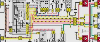
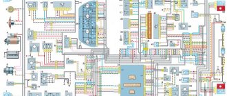
Relay and fuse diagram for VAZ 2110
The mounting block, in which the main fuses and relays are located, is in the cabin.
| Relay no. | Purpose |
| K1 | Lamp condition |
| K2 | Front glass cleaner |
| K3 | Relay-breaker for direction indicators and hazard warning lights |
| K4 | Low beam |
| K5 | Turning on the high beams |
| K6 | Additional starter relay |
| K7 | Heated rear window |
| K8 | Rear fog light |
| Fuse no. | Current (amps) | Description of fuses |
| F1 | 5 | License plate lamps. Instrument lighting lamps. Indicator lamp. Trunk light. Left side lamp |
| F2 | 7,5 | Near left headlight |
| F3 | 10 | Far left headlight |
| F4 | 10 | Right fog light |
| F5 | 30 | Door window motors |
| F6 | 15 | Portable lamp or socket |
| F7 | 20 | Engine cooling fan motor. Sound signal |
| F8 | 20 | Heated rear window. Turning on the heated rear window |
| F9 | 20 | Recirculation valve. Windshield and headlight cleaners and washers. Rear window heating coil |
| F10 | 20 | Reserve |
| F11 | 5 | Right side light |
| F12 | 7,5 | Right low beam |
| F13 | 10 | Right high beam. High beam warning lamp |
| F14 | 10 | Left fog light |
| F15 | 20 | Electrically heated seats. Trunk lock lock |
| F16 | 10 | Relay-breaker for direction indicators and hazard warning lights (in hazard warning mode). Hazard warning lamp |
| F17 | 7,5 | Interior lighting. Individual lighting. Illuminated ignition switch. Brake light bulbs. Clock or trip computer |
| F18 | 25 | Glove compartment lighting. Heater controller. Cigarette lighter. |
| F19 | 10 | Locking door locks. Relay for monitoring the health of brake light lamps and side lights. Direction indicators with warning lamps. Reversing light. Generator excitation winding. On-board control system display unit. Instrument cluster. Clock or trip computer |
| F20 | 7,5 | Rear fog light |
Main unit
The main mounting block is located near the driver's seat on the front panel, to the left of it. The niche is closed by a plastic lid with a shutter above it in the shape of a button - to open it you need to press it. Under the cover there are fuses, numbered in the diagram from F1 to F20 - they are responsible for all vehicle control elements, except for those placed in an additional block (there are three of them). The power of the fuses is different. There are also eight relays responsible for the main elements of the car control power circuit.
Console additional mounting block
You can find it inside the center console. It is located behind a plastic cover attached with screws, to the left of the front passenger seat. The block contains three relays and three fuses. In particular:
- Fan motor relay;
- Ignition relay;
- Fuel pump motor relay;
- Engine ECU and ignition module fuse;
- Fuse for electronic elements of the fuel supply system;
- Fuse for the electrical circuit of the speed and oxygen sensors, as well as the air flow meter and the canister purge valve.
The power of all fuses is rated at 15 Amps.
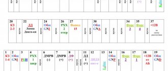
In the diagram, the letters indicate the following colors:
- B - white;
- Ch - black;
- F - yellow;
- O - orange;
- G - blue;
- P - pink;
- Z - green;
- C - gray;
- K - brown;
- P - red.
If the letters are together, then wires of two colors must be connected to the plug.
Changes in switching and layout of mounting blocks
The most important innovation in the VAZ 2110 fuse box from old to new models affected the location of the fog lamp fuse. In the first modifications, this device was located behind the block, and not inside it, and was supported by a bundle of wires, without being equipped with a board. Over time, the designers provided a special board for it, which was still located outside the main unit, but was placed to the left of the console. Only ten years later did it find a place among the other fuses.
Blocks with different layouts differ in numbering. The first models with 6 relays have the number 2110-3722010, while those equipped with 7 devices were marked 2110-3722010-08, and the most modern ones - 2110-3722010-01. Modifications that do not have relay legs for turning on the front lighting are marked as 21110-3722010-12. Also, the manufacturer produces units equipped with legs, but not relay K1, which can be either with or without jumpers - in both cases, independent installation of the device or jumpers instead of it is allowed.
Main unit
The main block with fuses and relays is located in the cabin, on the left side, under the control panel. To access, press the latch switch.
Photo - diagram Option 1
Scheme Option 2
Block 2110 - 3722010
Scheme Option 3
Description of fuses
Fuse number 18 at 25A is responsible for the operation of the cigarette lighter.
The fog lamp fuse is installed separately in the instrument panel niche behind the main unit.
Relay purpose
Electrical diagram of the block
Let's sum it up
Taking into account the above information, it becomes clear that the uninterrupted operation of the electric fuel pump of the VAZ 2110 or any other car will depend on correct and timely preventive maintenance, as well as on careful operation and compliance with certain rules.
Only clean fuel should be poured into the tank and the fuel filter should be changed promptly. It may also be necessary to periodically change or clean the fuel pump strainer, use a moisture displacer from the gas tank, etc.
Please note, it is not recommended to drive with an empty tank as the pump does not cool properly
Finally, we note that in the event of malfunctions in the operation of the internal combustion engine, it is quite possible to diagnose and replace the fuel pump with your own hands in a regular garage (if you have the tools)
However, working with the fuel system will require increased caution and compliance with all safety measures. If you are not confident in your abilities, it is better to contact experienced specialists