Remember one important thing, before you start disassembling the stove, wiper, headlight or anything else - make sure that the fuse responsible for this circuit has not blown. And in addition to the fuse, make sure that power is supplied to the non-working unit, because the mounting block and wiring of the car Over time, subject to external factors and influences, it may fail. The wire can most often suffer mechanical damage, the connectors can oxidize, but a track in the fuse block can burn out or even some of the conductive elements simply rot into dust.
By the way, it’s not for nothing that we focus attention on the latter - the location of the fuse box in the “chisel-samar” family is not entirely successful, water often gets on it, and due to the design features and its poor protection from moisture, various troubles are practically “guaranteed” by the manufacturer.
Today we will look at the diagram and location of fuses and relays VAZ 2113, 2114, 2115
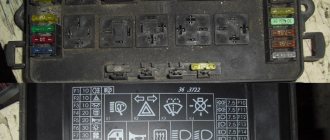
VAZ 2114 fuse mounting block diagram
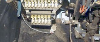
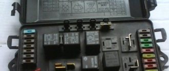
The fuse box in the VAZ-2114 is located under the hood, to the left in the direction of travel of the car, on the edge under the left wiper you will see a black box. To open it, you need to move two latches on the left. We remove the cover, there are relays and fuses.
There is a marking on the inside of the cover indicating the purpose of the relays and fuses.
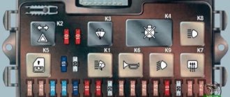
Below is the purpose of all relays and fuses in the VAZ-2113 and 2114
| K1 | Electric fan relay |
| K2 | Relay-breaker for direction indicators and hazard warning lights |
| K3 | Wiper relay |
| K4 | Relay for monitoring the health of brake lamps and side lights |
| K5 | Power window relay |
| K6 | Horn relay |
| K7 | Heated rear window relay |
| K8 | High beam relay |
| K9 | low beam headlight relay |
Circuits protected by fuses
| Fuse no. | Protected Circuits |
| F1(20A) | Relay for turning on rear fog lights. Rear fog lamps. Rear fog lamp activation indicator |
| F2(10A) | Turn signal lamps. Relay-breaker for direction indicators and hazard warning lights (in hazard warning mode). Hazard warning lamp |
| F3(10A) | Interior lighting. Individual interior lighting lamp. Ignition switch illumination lamp. Brake light bulbs. Trip computer |
| F4(20A) | Cigarette lighter fuse VAZ 2114.Relay for turning on the heated rear window (contacts). Rear window heating element. |
| F5(20A) | Sound signal. Relay for turning on the sound signal (coil). Horn relay (contacts), Relay switching of the electric fan (contacts). Cooling fan motor |
| F6(30A) | Power window switches. Electric windows. Power window relay (contacts) |
| F7(20A) | Heater motor. Washer motor. Rear window washer motor. Rear window wiper motor. Electric windshield wiper relay (winding). Glove compartment lamp |
| F8(7.5A) | Right fog lamp |
| F9(7.5A) | Left fog lamp. Fog light relay (contacts) |
| F10(7.5A) | Turn indicators in turn signal mode and corresponding indicator lamp. Fan motor activation relay (winding). Indicator lamp for fuel reserve, oil pressure, parking brake, brake fluid level. Battery charge indicator lamp. Instrument cluster.Voltmeter. Carburetor electro-pneumatic valve control system. Parking brake warning light relay |
| F11(7.5A) | Side lamps on the starboard side |
| F12(7.5A) | Right headlight (low beam) |
| F13(7.5A) | Left headlight (low beam) |
| F14(7.5A) | Left headlight (high beam). Indicator lamp for turning on the high beam headlights. |
| F15(7.5A) | Right headlight (high beam). |
| F16(15A) | Relay-breaker for direction indicators and hazard warning lights (in direction indicator mode). |
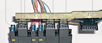
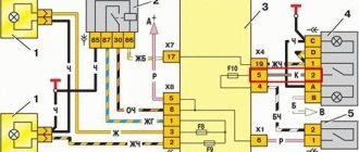
Connection diagram inside the VAZ-2114 and VAZ-2115 fuse box
(the outer number in the designation of the wire tip is the number of the block, and the inner number is the conventional number of the plug)
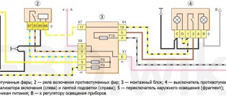
Rear fog lamp relay
In order for the user to quickly and easily diagnose the operation of mechanisms and devices, the designers placed the rear fog light relays separately from the main units.
The element is located under the dashboard, where the hood opening hook is installed. The starter control module is also mounted here.
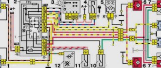
Connection diagram of the VAZ 2114 mounting block
(the outer number in the designation of the wire tip is the number of the block, and the inner number is the conventional number of the plug): K1 – relay for turning on the headlight cleaners; K2 – relay-interrupter for direction indicators and hazard warning lights; K3 – windshield wiper relay; K4 – lamp health monitoring relay; K5 – power window relay; K6 – relay for turning on sound signals; K7 – relay for turning on the heated rear window; K8 – headlight high beam relay; K9 – relay for low beam headlights; F1-F20 – fuses
How to remove the cigarette lighter
Sometimes the cause of the breakdown is not the fuse. In this case, repairs are performed. To remove the cigarette lighter, perform the following steps:
- Turn off the engine and open the engine compartment. Disconnect the negative terminal from the battery. This prevents burnout of on-board network elements during repair work.
- Remove the protective pad located to the right of the driver’s foot. To do this, unscrew the screws.
- Disconnect the cigarette lighter plug. Remove the lighting fixture with the socket.
- The metal clips are pulled out. This will make it easier to remove the device.
- Remove the metal cylinder.
The most common problem is why the fuse blows. The place where the cigarette lighter fuse is located, how to replace it and what to do if after replacement the cigarette lighter still does not work.
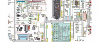
Electrical diagram of VAZ 2115 – 20 cars (left half):
1 – headlights; 2 – fog lights; 3 – air temperature sensor; 4 – electric motor of the engine cooling system fan; 5 – blocks connected to the wiring harness of the ignition system; 6 – engine compartment lamp switch; 7 – block for connection to a single-wire type audio signal; 8 – sound signal; 9 – washer fluid level sensor; 10 – front brake pad wear sensors; 11 – oil level sensor; 12 – generator; 13 – engine compartment lamp; 14 – coolant temperature indicator sensor; 15 – starter; 16 – battery; 17 – relay for turning on fog lights; 18 – coolant level sensor; 19 – brake fluid level sensor; 20 – reverse light switch; 21 – windshield wiper gearmotor; 22 – oil pressure warning lamp sensor; 23 – block for connecting to the rear window washer electric motor; 24 – windshield washer electric motor; 25 – instrument cluster; 26 – mounting block. Conventional numbering of plugs in blocks: A - block headlights; B — electric fuel pump block; C — blocks of the mounting block, ignition switch, windshield wiper gearmotor; D — interior lamp
Operating principle, design and characteristics of fuses
A protective device of this type consists of a housing, which is usually made of high-strength ceramics or special glass, and a fusible insert made of a conductive metal or alloy.
The body performs several functions:
- a fuse-link is built into it in a special way so that when the rated current of the insert is exceeded, it melts or breaks;
- the working thread is inserted into the chamber to extinguish the electric arc that occurs when the circuit breaks; this chamber is equipped in the housing;
- on the body, in those places and in the form as provided for by the fuse design, there are working contacts through which it must be connected to the general network.
Information about the characteristics of this protective device is printed on the housing. This is the rated current of the fuse link and the rated current of the fuse body at which it breaks.
According to their performance characteristics, these protective elements are divided into:
- fast-acting;
- low voltage;
- designed for medium voltage;
- manufactured for high voltages.
In automotive networks, the first two types are used.
The defining point showing the purpose of a particular protective device with a fuse link is its current characteristics. It is she who speaks about the range in which this element is ready to work.
- To protect electric motors, fuses are installed whose inserts can withstand the rated current and its excess for a sufficiently long time necessary to start the main mechanism and reach its operating range. As a rule, such chargers (protective devices) are marked - g - as devices ready for protection from both overload and short circuit.
- There are protective devices that operate effectively during short circuits and protect all equipment from very high voltage currents. Such chargers are marked - a - for protection only against short circuits.
Fuses for cars have several versions:
- low-current inserts, in networks up to 20 A, made of glass with a thin wire insert, there are ceramic cases, the ends are made of metal;
- fork inserts, most commonly used in vehicles, come in miniature and regular types.
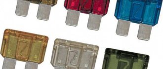
According to GOST, a painting system for fusible chargers has been adopted depending on the rated current of the insert. 2 A - gray, 4 A - pink, 5 A - orange-yellow, 7.5 A - brown, 10 A - red, 15 A - blue, 20 A - yellow, 25 A - white, 30 A - green.
Fuse colors
DIY repair
If the cigarette lighter does not work due to a burnt-out fusible element, perform the following steps:
- Clean the contacts of the socket in which the fuse is located. Loose elements are tightened.
- Check the device with a multimeter. The lighting ring is connected to the electrical circuit in series. Burnout of the lamp leads to a break in the cigarette lighter circuit. Devices connected to it do not work. After replacing the lamp, the device's functionality is restored.
- Check the heating coil with a multimeter. The probes are applied to the contacts. If 0 or 1 appears on the device screen, the spiral is faulty. The devices connected to the socket function normally, the cigarette lighter does not heat up. Replacing the device helps resolve the problem.
Connection diagram
When repairing a cigarette lighter, it is worth remembering in what order the contacts for connecting the wires are located. The socket is equipped with a light filter, making it easier to find the connector in the dark.
The connection diagram includes 3 cables that should go to the cigarette lighter components:
- The red cable is responsible for heating the coil. Connects to the battery via a 20 A fuse.
- The yellow wire, responsible for powering the lighting ring, is connected to the battery.
- The black ground cable is connected to the cigarette lighter body, the second to the body.
The fallen cables are connected according to the diagram.
- Car seat for newborns in a lying position
- Kalina cigarette lighter does not work
- Cigarette lighter fuse Grant
- Which engine is the most powerful