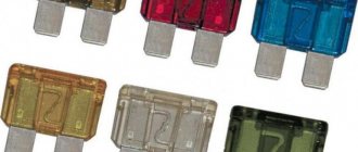
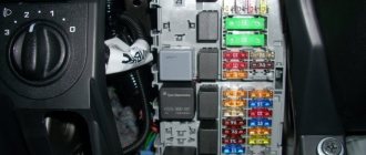
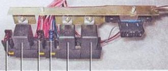
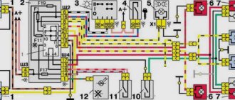
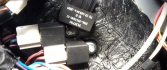
The relay and fuse box is also called the mounting block or black box. In the event of a car breakdown related to electrical equipment, the fuses and relays are first checked. If a fuse is blown, you must first determine the cause of its blown before replacing it.
Where are the fuses on the Priora?
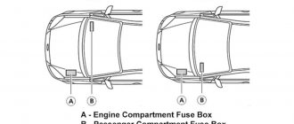
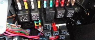
- The main mounting block of the Priora is closed with a lid and located at the driver’s left foot. To open it, you need to turn three latches 90° and unclip the lid.
- The fuse box is under the hood, which is located near the expansion tank.
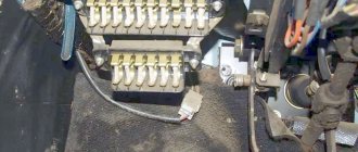
- Another mounting block, which is located near the left foot of the front passenger. To gain access to the fuses and relays, unscrew several screws with a Phillips screwdriver.
Below is a description of each fuse and relay block in order.
Electromagnetic relay
An electromagnetic relay is a switching device designed to relieve contacts. The work is based on the law of electromagnetic induction.
In cars, relays are used to unload contacts on control buttons, so that they, in turn, do not melt or heat up when more current appears on them. The relay consists of moving and non-moving contacts, a DC coil, a return spring, a coil core and an armature.
Relay operating principle
When a current appears on the relay coil, a magnetic field is formed in it, which in turn begins to attract the armature to which the movable contacts of the relay are attached. As a result, the moving contacts close with the fixed ones and the electrical circuit is completed.
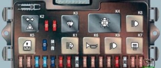
Priora fuse box diagram
| Fuse no. | Current strength, A | "Standard" and "Norm" | “Norma” with air conditioning and “luxury” |
| F1 | 25 | Engine cooling radiator fan | Reserve |
| F2 | 25 | Heated rear window | Mounting block, rear window heating relay (contacts). Electrical package controller, contact “10” of XP2 block. Rear window heating element. |
| F3 | 10 | Right headlight, high beam | Right headlight, high beam lamp. Instrument cluster, headlight high beam indicator. |
| F4 | 10 | Left headlight, high beam | |
| F5 | 10 | Sound signal | Mounting block, horn relay. Sound signal. |
| F6 | 7.5 | Left headlight, low beam | |
| F7 | 7.5 | Right headlight, low beam | |
| F8 | 10 | Alarm signal | Mounting block, alarm relay. Alarm sound. |
| F9 | 25 | Priora heater fuse | Reserve |
| F10 | 7.5/10* | Interior lighting, instrument panels, brake light | Instrument cluster, pin “20”. Brake light switch. Brake light bulbs. Interior lighting unit. Interior lighting. The door sill light on the right front door. Additional brake signal. |
| F11 | 10/20* | Wiper | Mounting block, high speed windshield wiper relay. Switch for cleaners and washers, contact “53a”. Wiper and washer switch, contact “53ah”. Heated rear window switch. Mounting block, rear window heating relay (winding). Windshield wiper motor. Rear window wiper motor (2171,2172). Windshield washer motor. Rear window washer motor (2171,2172). Airbag control unit, pin “25”. |
| F12 | 20/10* | Terminal 15 devices | Instrument cluster, pin “21”. Electrical package controller, contact “9” of block X2. Electromechanical power steering control unit, contact “1” of block X2. Reversing light switch. Reversing lamps. Parking system control unit, contacts “11” and “14”. |
| F13 | 15 | Cigarette lighter fuse Priora | |
| F14 | 5 | Left headlight, parking light, license plate light, trunk light | Side light lamps (left side) Instrument cluster, main light indicator License plate lights Trunk light Electrical package controller, pin “12” of block X2 |
| F15 | 5 | Right headlight, parking light | Side light lamps (right side) Glove compartment lamp |
| F16 | 10 | Terminal 15 ABS | Hydraulic unit, contact "18" |
| F17 | 10 | Left fog lamp | |
| F18 | 10 | Right fog lamp | |
| F19 | 15 | Seat heating | Seat heating switch, contact "1" Front seat heaters |
| F20 | 5/10* | Immobilizer control unit | Recirculation switch (switch on) Mounting block, relay for low beam headlights and parking lights (automatic lighting control system) Heater electric fan relay Automatic lighting control switch Windshield wiper and external lighting control unit, contacts “3”, “11” Automatic climate control system controller installation, pin “1” Automatic window cleaning system sensor (rain sensor), pin “1” |
| F21 | 7.5/5* | Rear fog lights | Light switch, contact "30" Diagnostic block, contact "16" Clock Automatic climate control system controller, contact "14" |
| F22 | -/20* | Reserve | Windshield wiper motor (automatic) Mounting block, windshield wiper relay and windshield wiper high speed relay, (contacts) |
| F23 | -/7.5* | Reserve | Windshield wipers and external lighting control unit, pin “20” |
| F24-F30 | Reserve | ||
| F31 | 30 | Electrical package control unit | Electrical package controller, terminal “2” of block X1 Electrical package controller, terminal “3” of block X1 Driver’s door module, pin “6” Threshold light of the left front door |
| F32 | Reserve | ||
* - for the “Norma” configuration with air conditioning and “luxury”
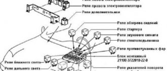
| Relay | "Norm" | "Norma" with air conditioning | "Lux" |
| K1 | relay for turning on the electric radiator fan of the engine cooling system | Reserve | Relay for turning on the low beam and side lights of the headlights (automatic lighting control system) |
| K2 | rear window heating relay | ||
| K3 | starter activation relay Priora | ||
| K4 | additional relay (ignition relay) | ||
| K5 | space for backup relay | ||
| K6 | windshield washer and wiper relay | ||
| K7 | headlight high beam relay | ||
| K8 | horn relay | ||
| K9 | alarm relay | ||
| K10 | Reserve | Fog light relay | |
| K11 | Reserve | Front seat heating relay | |
| K12 | Reserve | ||
EUR - what is it?
Electric power steering is a kind of electric motor that helps the driver turn the steering wheel with less effort. The EUR is installed on the steering wheel shaft and, when the engine is running, helps to rotate the steering wheel, powered by electrical voltage.
The main task of the ESD in a car is to reduce the force of rotation of the steering wheel by the car driver.
What it consists of:
- Steering shaft;
- Torsion shaft;
- Electrical engine;
- EUR control unit;
- Motor rotor sensor;
- Torque sensor;
- Circuit breakers;
The components of the EUR include the following elements:
- Steering rack;
- Steering wheel;
- Speed sensor;
- Steering cardans;
All these details directly affect the operation of the electric power steering of the Lada Priora.
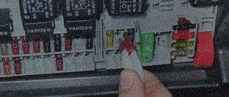
Location of Priora fuses under the hood
- F1 (30 A) – power supply fuse for the electronic engine control system (ECM);
- F2 (60 A) – fuse for the power supply circuit of the engine cooling system fan (power circuit), additional relay (ignition relay), rear window heating, electrical package controller;
- F3 (60 A) – fuse for the power supply circuit of the electric fan of the engine cooling system (relay control circuit), sound signal, alarm signal, ignition switch, instrument cluster, interior lighting, brake light, cigarette lighter;
- F4, F6 (60 A) – generator power circuit fuses;
- F5 (50 A) – fuse for the power supply circuit of the electromechanical power steering
Relay and fuse box for Halla air conditioner
- right electric fan power supply fuse (30 A);
- fuse for the power supply circuit of the left electric fan (30 A).
- right electric fan relay;
- additional relay (sequential activation of left and right electric fans);
- left electric fan relay;
- heater fan power supply fuse (40 A);
- compressor power supply fuse (15 A);
- heater fan relay;
- compressor relay.
Panasonic air conditioner relay and fuse box
- Heater fan maximum speed
- Right fan
- Fan sequential relay (low speed)
- Left fan
- Left fan fuse (low speed)
- Right fan
- Heater fan
- Compressor
- Heater fan
- Compressor
Differences between EUR and power steering
The electric amplifier differs from the hydraulic one in the absence of fluid and the pump necessary to pump this fluid. Also, the hydraulic power steering operates entirely on mechanics, unlike the electric power steering, in which mechanics are involved only in the rack and steering wheel. EUR is much simpler and easier to maintain, but in terms of repairs it is much more expensive.
Advantages and disadvantages of EUR over power steering
Although the EUR is more modern and technologically advanced, it has both advantages and disadvantages over the power steering.
Advantages:
- The simplest design that does not require constant monitoring of the liquid level (dixtron);
- There is no need to service the power steering pump, since it simply does not exist;
- Reduction of force with increasing vehicle speed;
- Ability to programmatically adjust steering wheel force;
- Reliability of the design;
- Compact, no bulky pump in the engine compartment and no extra hoses;
- The simplicity of the steering rack and its reliability, since it is dry and there is simply nothing to leak in it (everyone knows very well about the disease of “wet” racks);
Flaws:
- High power consumption, at some points the electric power steering can take up to 40% of the electrical power of the car’s generator and cause voltage drops in the on-board network;
- Possibility of overheating of the electric motor when driving on a dirt road (track) up to the complete shutdown of the power steering;
As you can see, the more modern power steering has many more advantages, which is why it is gaining great popularity among cars at the present time.
Additional mounting block Priora
- F1 (15 A) – main relay and starter interlock circuit fuse;
- F2 (7.5 A) – fuse for the power supply circuit of the ECU (controller);
- F3 (15 A) – Priora fuel pump fuse;
- K1 – main relay;
- K2 is the place where the Priora fuel pump relay is located.
Attention!
The relay and fuse diagram may differ depending on the configuration and production date of the vehicle. Current diagrams of the mounting block are presented in the operating manual for the date of manufacture of the vehicle ().
Let us remind you that on our website you can find detailed instructions for repairing the Lada Priora with your own hands.
Keywords: Lada Priora mounting block | Lada Priora torpedo
17 8 7 6 4 5
Share on social networks:
Additional fuses and relays in the passenger compartment (fuel injection system)
Location
The relay and fuse box is located on a bracket under the instrument console, next to the controller. To access this block, remove the right side panel of the floor tunnel lining.
Circuit breakers
1
- Since 2007 (7.5A): Controller constant power supply circuit
- Controller constant power supply circuit
2 (15A)
- Fuel pump
3 (15A)
- From 2007: Main relay
- Not used
4 (15A)
- Since 2007: Not used
- Main relay
Relay
K1
- Fuel pump relay
K2
- Main relay
How to choose
Having decided to replace a relay or fuse in a Priora, take full responsibility for their selection and purchase. Under no circumstances should you buy cheap parts of unknown quality and origin.
It is better to give preference to original products produced by VAZ. As a last resort, buy relays or fuses from one of the well-known companies, such as Bosh, Hella or Tesla.
Today, every Priora is equipped with electric power steering (EPS), and this also applies to basic configurations. At the beginning of the car's release, the unit came as an additional comfort option. Owners of this model know that the unit often jams and fails. The power steering has become the weak point of the Priora, but if necessary, repairs can be done with your own hands. In this material we will take a detailed look at what the EUR is, what breakdowns occur in this unit and how to fix them yourself. You should take on the job only if you have experience in servicing a car, since when replacing it we will have to disassemble half of the dashboard.
Technical characteristics of the EUR
| Name | Index |
| Rated voltage, (V) | 13,5 |
| Operating voltage, (V) | 10-15 |
| Maximum current, (A) | 55 |
| Current at rest, (A) | 0,5 |
| Moment of resistance at rest, (Nm) | 0,8 |
| Weight, (kg) | 9,3 |
| Operating temperature, (⁰С) | -40…65 |
Removal and installation
To carry out work on removing and installing the electric power steering on a Priora, you need to prepare a special tool that will be needed during the work process.
You will need:
- Hammer;
- Wedge (a chisel will do);
- Ratchet;
- Ratchet extension;
- Head for “8” and “13” mm;
After preparing the tool, you can begin to work.
Removal
- Disable the mass mark from the battery;
- dismantle the steering column casing;
- Remove the ignition switch by unscrewing the bolts;
- Remove all connectors from the power steering unit;
- We unscrew the steering cardan nut and use a wedge to loosen its engagement on the splines;
- Unscrew the nuts securing the amplifier to the body (4 pcs);
- We remove the structure from the car;
- We assemble in the reverse order;
Identifying signs of a problem
When the contacts burn out, the driver begins to hear clicks, indicating that the magnet is triggered. At the same time, there is an anchor in the starter, which remains motionless, and even if it moves, it moves extremely slowly. This happens when the contacts, or rather their working surface, are not completely connected, which causes:
- The copper splash is heated;
- The transient voltage begins to rise;
- An air gap immediately begins to appear.
As a result, a dielectric – oxide – appears on the surface. There is only one way you can fix everything. It is necessary to clean the deposits from the deposits that have formed. You can do this work yourself. If the damage is not large, then you can use a diamond file or use a student's eraser. When the device is severely damaged, it is better to replace it completely.
