Mazda 6 gg (1st generation) was produced in 2002, 2003, 2004, 2005, 2006, 2007 and 2008. During this time, the model was restyled. Delivered all over the world. In China and Japan it is known as Mazda Atenza.
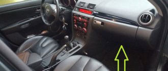
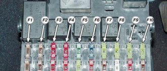
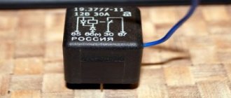
In this publication you will find a description of fuses and relays of the Mazda 6 gg with block diagrams and photos - examples of execution. Let's highlight the cigarette lighter fuse.
The design of the blocks and the purpose of their elements may differ and depend on the year of manufacture, region of delivery (USA, Europe, etc.) and level of equipment.
Mazda 6 GG fuse diagram under the hood
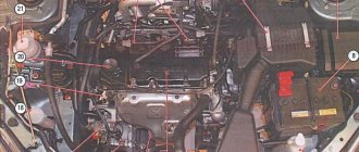
First, let’s clarify where the block with the protective elements of the Mazda 6 GG electrical network is located in the engine compartment.
Mazda 6 GG fuses and relays are mounted on the left wing of the Japanese car, next to the battery.
Fuse links in the engine compartment of the first generation Mazda 6 are responsible for the reliable and safe operation of the following devices:
- 1, 2, 3, 21, 35 – not used (spare);
- 4 – heating system for external mirrors (7.5A);
- 5, 22 – socket (5, 40A);
- 6 – power unit ECU (15A);
- 7 – Mass air flow sensor, power unit ECU;
- 8 – oxygen sensor (15A);
- 9, 10 – Mazda 6 1st generation low beam fuse for the right and left headlights (15A);
- 11, 12 – high beam front optics on the left and right;
- 13 – accelerator position controller (7.5A);
- 14 – emergency stop light warning;
- 15 – brake lights (15A);
- 16, 17 – control program of the internal combustion engine and automatic transmission (7.5A);
- 18 – fuel pump fuse Mazda 6 GG (20A);
- 19, 37 – additional electrical circuits (40, 15A);
- 20 – electric window lifts (30A);
- 23 – control unit of the heating complex, reversing lights (30A);
- 24 – heating radiator fan (40A);
- 25 – central locking Mazda 6 GG, interior lighting (40A);
- 26 – heating system (20A);
- 27 – rear glass heating system (40A);
- 28 – additional electrical circuits, ABS (60A);
- 29, 30 – auxiliary electrical circuits, air conditioning fan (30A);
- 31 – dashboard lighting, dimensions;
- 32 – interior lighting;
- 33 – electromagnetic type coupling;
- 34 – multimedia complex (15A);
- 36 – circuit for opening the fuel tank hatch (7.5A);
- 38 – cleaning mechanism for optics (20A);
- 39 – fog lights (15A);
- 40 – main fuse-link.
To ensure protection of electrical equipment along the block circuits in the engine compartment of a Japanese car, fuse links with a rated current of ten amperes are most often used. These include elements with serial numbers 7, 11, 12, 14, 16, 31, 32, 33, 40.
Relay unit under the hood
The Mazda 6 GI power unit of the engine compartment is equipped with the following relays:
- 1 – main fuse link Mazda 6 GG;
- 6, 8, 10, 18 – radiator cooling fan No. 2, 3, 4, 1;
- 7 – sound signal;
- 9 – starter relay;
- 11 – subwoofer;
- 12 – rear glass heating complex;
- 13 – PTF;
- 14 – air conditioning control program;
- 15 – main relay;
- 16 – optics;
- 17 – side lights;
- 19 – washing optics complex;
- 20 – PTF.
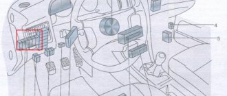
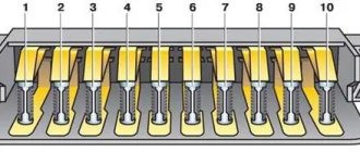
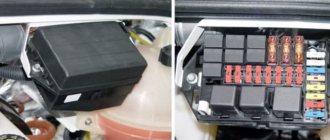
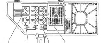
Block under the hood
It is located on the left side of the engine compartment, under the protective cover.
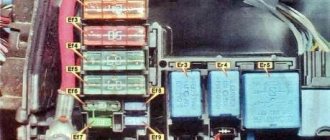
Relay circuit
Decoding
- 1 - main fuse
- 6 - cooling fan relay No. 2
- 7 - horn relay
- 8 — cooling system fan relay No. 3
- 9 - starter relay
- 10 - cooling fan relay No. 4
- 11 - bass speaker relay
- 12 - rear window heater relay
- 13 - fog lamp relay
- 14 - air conditioner relay
- 15 - main relay
- 16 - headlight relay
- 17 - size relay
- 18 - cooling fan relay No. 1
- 19 - headlight washer relay
- 20 - fog lamp relay
Fuse diagram for Mazda 6 GG (Atenza)
Description
| 1 | 20A SPARE Reserve |
| 2 | 15A SPARE Reserve |
| 3 | 10A SPARE Reserve |
| 4 | SPARE Reserve |
| 5 | 5A GLOW SIG Candles |
| 6 | 15A INJ Engine control system |
| 7 | 10A ENG BAR Air flow sensor, engine management system |
| 8 | 15A ENG BAR2 Oxygen sensor |
| 9 | 15A HEAD LR Low beam (right headlight) |
| 10 | 15A HEAD LL Low beam (left headlight) |
| 11 | 10A HEAD HL High beam (left headlight) |
| 12 | 10A HEAD HR High beam (right headlight) |
| 13 | SPARE Reserve |
| 14 | 10A HAZARD Alarm |
| 15 | 15A STOP Stop lights |
| 16 | 10A ENG+B Electronic engine and automatic transmission control unit |
| 17 | SPARE Reserve |
| 18 | 20A FUEL PUMP Fuel pump |
| 19 | 40A IG KEY 1 Fuse for various circuits |
| 20 | SPARE Reserve |
| 21 | SPARE Reserve |
| 22 | 40A GLOW Ignition |
| 23 | 30A IG KEY 2 Fuse for various circuits |
| 24 | 40A BLOWER Heater fan motor |
| 25 | 40A BTN Interior lighting, central locking |
| 26 | 20A HEATER Heater |
| 27 | 40A DEFOG Heated rear window / rear door glass |
| 28 | 60A ABS Anti-lock brake system, fuse for various circuits |
| 29 | 30A AD FAN Condenser fan motor, fuse for various circuits |
| 30 | 30A FAN Condenser fan motor, fuse for various circuits |
| 31 | 10A TAIL Side lights, instrument cluster illumination |
| 32 | 10A ILLUMI Interior lighting |
| 33 | 10A MAG Electromagnetic clutch |
| 34 | Radio tape recorder |
| 35 | 30A P.SEAT Seats |
| 36 | Reserve |
| 37 | 15A SEAT DEICER Fuse for various circuits |
| 38 | 20A H/CLEAN Headlight cleaner |
| 39 | 15A FOG Fog lights |
| 40 | 100A MAIN Main fuse |
Fuse box in the Mazda 6 interior before restyling
To gain access to the interior unit, where the fuses and relays of the Mazda 6 GG are located, you will need to remove the decorative cover under the dashboard.
The diagram of the protective devices of the Japanese car before the restyled version includes:
- R1 – fuel supply pump;
- R2 – heating radiator fan;
- 1 – ICE ECU;
- 2, 9 – instrument panel (5A);
- 3 – heating complex of seats and rear glass;
- 4 – additional electrical circuits, heating system for exterior mirrors (7.5A);
- 5 – wipers and washer complex (20A);
- 6 – SRS, ABS;
- 7 – reversing lights (5A);
- 8 – air conditioning control program;
- 10 – fuse for the cigarette lighter Mazda 6 GG;
- 11 – lighting of luggage and interior space;
- 12 – rear wipers (10A);
- 13 – mirror position regulator (5A);
- 14 – circuit for using auxiliary devices;
- 15, 17 – electric window lifts (20, 40A);
- 16 – central locking (30A).
Most of the fuse links in the power unit of the interior space of a Japanese car have a current rating of fifteen amperes. These include devices numbered 1, 2, 3, 6, 8, 10, 11, 14.
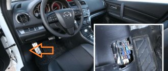
Block in the interior of Mazda 6 GG (Atenza)
Located at the bottom of the pillar, under the panel, near the driver's left foot.
Option 1
Photo example
Scheme
Description
| 1 | 15A ENGINE IG Engine control system |
| 2 | 15A METERIG Instrument cluster |
| 3 | 15A SEAT Heated seats, heated rear window |
| 4 | 7.5A M.DEF Heated mirrors, fuse for various circuits |
| 5 | 20A WIPER Windshield wipers and washers |
| 6 | 15A SAS Anti-lock brake system, active safety system (airbags) |
| 7 | 5A BACK Reversing light |
| 8 | 15A A/C Air Conditioner |
| 9 | 5A METER ACC Instrument cluster |
| 10 | 15A CIGAR Cigarette lighter |
| 11 | 15A ROOM Interior lighting, trunk/luggage compartment lighting |
| 12 | 10A R.WIPER Rear window/rear door glass wiper |
| 13 | 5A MIRROR Mirror control |
| 14 | 15A R.CIGAR Rear cigarette lighter |
| 15 | 20A P/WIND Electric window lift |
| 16 | 30A DOOR LOCK Central locking |
| 17 | 30A Electric window lift |
Fuse number 10 is 15A for the front cigarette lighter, 14 for the rear.
Option 2
Photo
Scheme
Designation
| 1 | 15A CIGAR Cigarette lighter |
| 2 | 15A ENGINE IG Engine control system |
| 3 | 10A A/C Air Conditioner |
| 4 | 5A MIRROR Mirrors |
| 5 | 10A SAS Anti-lock brake system ABS, active safety system (airbags) |
| 6 | 15A SEAT Seat heating |
| 7 | 5A METER ACC - Audio system illumination |
| 8 | 15A METER IG Instrument panel (Instrument cluster) |
| 9 | 10A R.WIP Rear Wiper |
| 10 | 30A D.LOCK Electric door locks |
| 11 | 15A R.CIGAR Rear Accessory Jack |
| 12 | 20A WIPER Windshield wiper and washer |
| 13 | 15A ROOM Interior lighting |
| 14 | SPARE Reserve |
| 15 | SPARE Reserve |
| 16 | SPARE Reserve |
In this version, fuse number 1 at 15A is responsible for the front cigarette lighter, fuse 11 for the rear.
Relay purpose
- R1 Fuel pump relay
- R2 Heater fan relay
Removal and replacement procedure
Changing power supply components will not cause any difficulties for Mazda owners. But how, if necessary, can you carry out the procedure for replacing the power supply yourself? We will talk about this further using the example of a salon power supply:
- First turn off the ignition and disconnect the battery from the power supply.
- Find the location of the power supply. This was stated at the beginning of the article.
- Remove the facing protective cover of the power supply unit.
- Disconnect the blocks with harnesses leading to the power supply. Using a screwdriver, unscrew the screw that secures it. Press the latch and remove the device.
- Replace the power supply with a new one, and install it in the reverse order.
Remove the protective trim from the interior
Following the steps, remove the power supply and replace it with a new one
Repair of heated seats Mazda CX-5
From time to time you may encounter some troubles. For example, a light bulb may not work. What to do in this case? Don't think about the problem, ignore it? Our repairs will be inexpensive. Any button will start working again. The front and rear seats will again be heated in a timely manner. It will be very comfortable to drive in the car in the morning to work or in the afternoon, in the evening for an unexpected meeting or a planned one. Repair of heated seats in Mazda 3, 6, CX 5, CX 7 is not often needed if the system is installed well. If the relay does not work, you need to contact a specialist. Doing anything on your own is much more difficult. It is much easier to change the situation for the better in the warm, well-lit room of our car service center than in a regular garage. The heated seats of Mazda 3 and 6 will be brought into working condition in the shortest possible time. Of course, it is not always possible to repair the heating system. Unfortunately, sometimes you need to install a new one. For example, it is better to change the Peugeot coupling system. If the fuse of an embedded system breaks, of course, it makes sense to try to replace it or repair it. Much depends on the system configuration. The fuse may fail and cause concern to the motorist; just in case, the system will have to be left off. Should I worry in vain and put off repairs until later? Our prices will pleasantly surprise you. In St. Petersburg, we are the best and are ready to prove it to you. Heated seats for Mazda 3, 6, cx 5 or any other model will be carried out in accordance with the standards, using good modern equipment. For safety, confidence that the early morning will be good, the interior is comfortable, a responsible approach and high-quality repairs are needed. That's exactly what will happen. There is no point in turning repairs into a tedious process. By entrusting the work to us, you will be able to see in practice: heated seats for the Mazda CX 5 and not only are a convenient option, a successful upgrade.
Fuse Box Diagrams
2013, 2014, 2015
Engine compartment
Assignment of fuses in the engine compartment (2013, 2014, 2015)
| № | DESCRIPTION | AMP RATING | SECURED COMPONENT |
| 1 | ADD FAN GE | 30 A | Cooling fan |
| 2 | IG2 | 30 A | To protect various circuits |
| 3 | Injector | 30 A | Engine management system |
| 4 | FAN DE | 40 A | – |
| 5 | P. WINDOW 1 | 30 A | Power windows (some models) |
| 6 | – | – | – |
| 7 | ADD FAN DE | 40 A | – |
| 8 | EVVT | 20 A | Engine management system |
| 9 | DEFOG | 40 A | Heated rear window |
| 10 | DC DC DE | 40 A | – |
| 11 | FAN GE | 30 A | Cooling fan |
| 12 | – | – | – |
| 13 | – | – | – |
| 14 | – | – | – |
| 15 | ENG.MAIN | 40 A | Engine management system |
| 16 | ABS/DSC M | 50 A | ABS, Dynamic Stability Control |
| 17 | Cabin. + B | 50 A | To protect various circuits |
| 18 | WIPER | 20 A | Windshield wiper and washer |
| 19 | HEATER | 40 A | Air conditioner |
| 20 | DC DC REG | 30 A | – |
| 21 | ENGINE.IG1 | 7.5 A | Engine management system |
| 22 | C/U IG1 | 15 A | To protect various circuits |
| 23 | H/L LOW L HID L | 15 A | Headlight (left) (with xenon headlights), low beam (left) (with halogen headlights) |
| 24 | B/L LOW R | 15 A | Low beam headlight (right) (with halogen headlights) |
| 25 | Engine3 | 15 A | Engine management system |
| 26 | ENGINE2 | 15 A | Engine management system |
| 27 | ENGINE1 | 15 A | Engine management system |
| 28 | IN | 15 A | Transmission control system (some models) |
| 29 | N/CLEANING | 20 A | – |
| 30 | A/C | 7.5 A | Air conditioner |
| 31 | ON THE PUMP | 15 A | – |
| 32 | STOP | 10 A | Brake lights |
| 33 | R.WIPER | 15 A | Anti-theft system (select models) |
| 34 | H/L HI | 20 A | High beam headlights |
| 35 | HID R | 15 A | Headlight (RH) (with Fusion Xenon headlights) |
| 36 | FOG | 15 A | Fog lights (some models) |
| 37 | ENG. + B | 7.5 A | Engine management system |
| 38 | AUDIO2 | 7.5 A | Audio system |
| 39 | GLOW SIG | 5 A | – |
| 40 | meter 2 | 7.5 A | – |
| 41 | METER1 | 10 A | Instrument panel |
| 42 | SRS1 | 7.5 A | Air bag |
| 43 | BOSE | 25 A | Model with Bose audio system |
| 44 | AUDIO1 | 15 A | Audio system |
| 45 | ABS/DSC S | 30 A | ABS, Dynamic Stability Control |
| 46 | FUEL PUMP | 15 A | Fuel system |
| 47 | FUEL WARM | 25 A | – |
| 48 | TAIL | 15 A | Tail lights, License plate light |
| 49 | FUEL PUMP2 | 25 A | – |
| 50 | DANGERS | 25 A | Flashers warning of danger. Turn Signals/Front Side Marker Lights, Parking Lights |
| 51 | DRL | 15 A | Daytime running lights (some models) |
| 52 | R.OUTLET2 | 15 A | Accessory sockets |
| 53 | HORN | 15 A | horn |
| 54 | ROOM | 15 A | overhead light |
Passenger cabin
Assignment of fuses in the passenger compartment (2013, 2014, 2015)
| № | DESCRIPTION | AMP RATING | SECURED COMPONENT |
| 1 | P.SEAT D | 30 A | Power seat (some models) |
| 2 | P.WINDOW3 | 30 A | Power windows (some models) |
| 3 | R.OUTLET3 | 15 A | – |
| 4 | P.WINDOW2 | 25 A | Power windows |
| 5 | SRS2/ESCL | 15 A | Seat weight sensor (some models) |
| 6 | D.LOCK | 25 A | Power door locks |
| 7 | WARM SEAT | 20 A | Seat heating (some models) |
| 8 | LUKE | 10 A | Hatch (some models) |
| 9 | F.OUTLET | 15 A | Accessory sockets |
| 10 | MIRROR | 7.5 A | Power adjustment mirror |
| 11 | R.OUTLET1 | 15 A | – |
| 12 | – | – | – |
| 13 | – | – | – |
| 14 | – | – | – |
| 15 | – | – | – |
| 16 | – | – | – |
| 17 | m.def | 7.5 A | Heated mirrors (some models) |
| 18 | – | – | – |
| 19 | – | – | – |
| 20 | In IND | 7.5 A | Automatic transmission shift indicator (some models) |
| 21 | P.SEAT P | 30 A | Power seat (some models) |
2016
Engine compartment
Assignment of fuses in the engine compartment (2016)
| № | DESCRIPTION | AMP RATING | SECURED COMPONENT |
| 1 | ADD FAN GE | 30 A | Cooling fan |
| 2 | IG2 | 30 A | To protect various circuits |
| 3 | Injector | 30 A | Engine management system |
| 4 | FAN DE | 40 A | – |
| 5 | P. WINDOW 1 | 30 A | – |
| 6 | – | – | – |
| 7 | ADD FAN DE | 40 A | – |
| 8 | EVVT | 20 A | Engine management system |
| 9 | DEFOG | 40 A | Heated rear window |
| 10 | DC DC DE | 40 A | – |
| 11 | FAN GE | 30 A | Cooling fan |
| 12 | EPB L | 20 A | Electric parking brake (left) |
| 13 | AUDIO | 40 A | Audio system |
| 14 | EPB R | 20 A | Electric parking brake (right) |
| 15 | ENG.MAIN | 40 A | Engine management system |
| 16 | ABS/DSC M | 50 A | ABS, Dynamic Stability Control |
| 17 | Cabin. + B | 50 A | To protect various circuits |
| 18 | WIPER | 20 A | Windshield wiper and washer |
| 19 | HEATER | 40 A | Air conditioner |
| 20 | DC DC REG | 30 A | For protecting various circuits (some models) |
| 21 | ENGINE.IG1 | 7.5 A | Engine management system |
| 22 | C/U IG1 | 15 A | To protect various circuits |
| 23 | H/L LOW L HID L | 15 A | Low beam headlights (LH) |
| 24 | B/L LOW R | 15 A | Low beam headlights (right) |
| 25 | Engine3 | 15 A | Engine management system |
| 26 | ENGINE2 | 15 A | Engine management system |
| 27 | ENGINE1 | 15 A | Engine management system |
| 28 | IN | 15 A | Transmission control system (some models) |
| 29 | N/CLEANING | 20 A | – |
| 30 | A/C | 7.5 A | Air conditioner |
| 31 | ON THE PUMP | 15 A | Transmission control system (some models) |
| 32 | STOP | 10 A | Brake lights |
| 33 | R.WIPER | 15 A | Anti-theft system (select models) |
| 34 | H/L HI | 20 A | High beam headlights |
| 35 | HID R | 15 A | – |
| 36 | FOG | 15 A | Fog lights (some models) |
| 37 | ENG. + B | 7.5 A | Engine management system |
| 38 | AUDIO2 | 7.5 A | Audio system |
| 39 | GLOW SIG | 5 A | – |
| 40 | meter 2 | 7.5 A | – |
| 41 | METER1 | 10 A | Instrument panel |
| 42 | SRS1 | 7.5 A | Air bag |
| 43 | BOSE | 25 A | Model with Bose audio (select models) |
| 44 | AUDIO1 | 15 A | Audio system |
| 45 | ABS/DSC S | 30 A | ABS, Dynamic Stability Control |
| 46 | FUEL PUMP | 15 A | Fuel system |
| 47 | FUEL WARM | 25 A | – |
| 48 | TAIL | 15 A | Tail lights, License plate light |
| 49 | FUEL PUMP2 | 25 A | – |
| 50 | DANGERS | 25 A | Hazard warning lights, Turn signals/Front side marker lights, Parking lights |
| 51 | DRL | 15 A | Daytime running lights (some models) |
| 52 | R.OUTLET2 | 15 A | Accessory sockets |
| 53 | HORN | 15 A | horn |
| 54 | ROOM | 15 A | overhead light |
Passenger cabin
Assignment of fuses in the cabin (2016)
| № | DESCRIPTION | AMP RATING | SECURED COMPONENT |
| 1 | P.SEAT D | 30 A | Power seat (some models) |
| 2 | P.WINDOW3 | 30 A | Power windows (some models) |
| 3 | R.OUTLET3 | 15 A | – |
| 4 | P.WINDOW2 | 25 A | Power windows |
| 5 | SRS2/ESCL | 15 A | – |
| 6 | D.LOCK | 25 A | Power door locks |
| 7 | WARM SEAT | 20 A | Seat heating (some models) |
| 8 | LUKE | 10 A | Hatch (some models) |
| 9 | F.OUTLET | 15 A | Accessory sockets |
| 10 | MIRROR | 7.5 A | Power adjustment mirror |
| 11 | R.OUTLET1 | 15 A | – |
| 12 | – | – | – |
| 13 | – | – | – |
| 14 | – | – | – |
| 15 | – | – | – |
| 16 | – | – | – |
| 17 | m.def | 7.5 A | Heated mirrors (some models) |
| 18 | R.SEAT W | 20 A | Seat heating (some models) |
| 19 | R.SHADE | 7.5 A | – |
| 20 | In IND | 7.5 A | Automatic transmission shift indicator (some models) |
| 21 | P.SEAT P | 30 A | Power seat (some models) |
2017
Engine compartment
Assignment of fuses in the engine compartment (2017)
| № | DESCRIPTION | AMP RATING | SECURED COMPONENT |
| 1 | ADD FAN GE | 30 A | Cooling fan |
| 2 | IG2 | 30 A | To protect various circuits |
| 3 | Injector | 30 A | Engine management system |
| 4 | FAN DE | 40 A | – |
| 5 | P. WINDOW 1 | 30 A | – |
| 6 | – | – | – |
| 7 | ADD FAN DE | 40 A | – |
| 8 | EVVT SCR1 | 20 A | Engine management system |
| 9 | DEFOG | 40 A | Heated rear window |
| 10 | DCDC DE | 40 A | – |
| 11 | FAN GE | 30 A | Cooling fan |
| 12 | EPB L | 20 A | Electric parking brake (left) |
| 13 | AUDIO | 40 A | Audio system |
| 14 | EPB R | 20 A | Electric parking brake (right) |
| 15 | ENG.MAIN | 40 A | Engine management system |
| 16 | ABS/DSC M | 50 A | ABS, Dynamic Stability Control |
| 17 | Cabin. + B | 50 A | To protect various circuits |
| 18 | WIPER | 20 A | Windshield wiper and washer |
| 19 | HEATER | 40 A | Air conditioner |
| 20 | DC DC REG | 30 A | – |
| 21 | ENGINE. IG1 | 7.5 A | Engine management system |
| 22 | C/U IG1 | 15 A | To protect various circuits |
| 23 | H/L LOW L HID L | 15 A | Low beam headlights (LH) |
| 24 | B/L LOW R | 15 A | Low beam headlights (right) |
| 25 | Engine3 | 15 A | Engine management system |
| 26 | ENGINE2 | 15 A | Engine management system |
| 27 | ENGINE1 | 15 A | Engine management system |
| 28 | IN | 15 A | Transmission control system (some models), ignition switch |
| 29 | N/CLEANING | 20 A | – |
| 30 | A/C | 7.5 A | Air conditioner |
| 31 | ON THE PUMP | 15 A | – |
| 32 | STOP | 10 A | Brake lights |
| 33 | R. VIPER | 15 A | Anti-theft system (select models) |
| 34 | H/L HI | 20 A | High beam headlights |
| 35 | HID R ST. HEATER | 15 A | Heated steering wheel (select models) |
| 36 | FOG | 15 A | Fog lights (some models) |
| 37 | ENG. + B | 7.5 A | Engine management system |
| 38 | AUDIO2 | 7.5 A | Audio system |
| 39 | GLOW SIG | 5 A | – |
| 40 | meter 2 | 7.5 A | – |
| 41 | METER1 | 10 A | Instrument panel |
| 42 | SRS1 | 7.5 A | Air bag |
| 43 | BOSE | 25 A | Model with Bose audio system |
| 44 | AUDIO1 | 15 A | Audio system |
| 45 | ABS/DSC S | 30 A | ABS, Dynamic Stability Control |
| 46 | FUEL PUMP | 15 A | Fuel system |
| 47 | FUEL WARM | 25 A | – |
| 48 | TAIL | 15 A | Tail lights, License plate light |
| 49 | FUEL PUMP2 SCR2 | 25 A | – |
| 50 | DANGERS | 25 A | Hazard warning lights, Turn signals/Front side marker lights, Parking lights |
| 51 | DRL | 15 A | Daytime running lights (some models) |
| 52 | R.OUTLET2 | 15 A | Accessory sockets |
| 53 | HORN | 15 A | horn |
| 54 | ROOM | 15 A | overhead light |
Passenger cabin
Assignment of fuses in the cabin (2017)
| № | DESCRIPTION | AMP RATING | SECURED COMPONENT |
| 1 | P.SEAT D | 30 A | Power seat (some models) |
| 2 | P.WINDOW3 | 30 A | Power windows (some models) |
| 3 | R.OUTLET3 | 15 A | – |
| 4 | P.WINDOW2 | 25 A | Power windows |
| 5 | SRS2/ESCL | 15 A | – |
| 6 | D.LOCK | 25 A | Power door locks |
| 7 | WARM SEAT | 20 A | Seat heating (some models) |
| 8 | LUKE | 10 A | Hatch (some models) |
| 9 | F.OUTLET | 15 A | Accessory sockets |
| 10 | MIRROR | 7.5 A | Power adjustment mirror |
| 11 | R.OUTLET1 | 15 A | – |
| 12 | – | – | – |
| 13 | – | – | – |
| 14 | – | – | – |
| 15 | – | – | – |
| 16 | – | – | – |
| 17 | m.def | 7.5 A | Heated mirrors (some models) |
| 18 | R.SEAT W | 20 A | Seat heating (some models) |
| 19 | R.SHADE | 7.5 A | – |
| 20 | In IND | 7.5 A | Automatic transmission shift indicator (some models) |
| 21 | P.SEAT P | 30 A | Power seat (some models) |
2018, 2022, 2020
Engine compartment
Assignment of fuses in the engine compartment (2018, 2022, 2020)
| № | Name | Amplifier rating | Protected Component |
| 1 | AUDIO DCDC REG | 30 A | 2018: Audio system (some models), To protect various circuits 2019-2020: Audio system |
| 2 | IG2 | 30 A | To protect various circuits |
| 3 | INJECTOR ENG. SUB | 30 A | Engine management system (some models) |
| 4 | SCR1 EVVT | 20 A | Engine management system (some models) |
| 5 | P. WINDOW 1 | 30 A | Power windows |
| 6 | IG1 2 | 30 A | To protect various circuits |
| 7 | – | – | – |
| 8 | ADD FAN DE | 50 A | Cooling fan (some models) |
| 9 | DEFOG | 40 A | Heated rear window |
| 10 | DCDC DE | 40 A | For protecting various circuits (some models) |
| 11 | EPB R | 20 A | Electric parking brake (EPB) (RH) |
| 12 | EPB L | 20 A | Electric Parking Brake (EPB) (LH) |
| 13 | Cabin. + B | 50 A | To protect various circuits |
| 14 | FAN GE | 30 A | Cooling fan (some models) |
| 15 | ENG.MAIN | 40 A | Engine management system |
| 16 | ABS/DSC M | 50 A | ABS, Dynamic Stability Control |
| 17 | HEATER | 40 A | Air conditioner |
| 18 | WIPER | 20 A | Windshield wiper and washer |
| 19 | FAN DE | 50 A | Cooling fan (some models) |
| 20 | ADD FAN GE | 30 A | Cooling fan (some models) |
| 21 | Engine3 | 15 A | Engine management system |
| 22 | ENGINE2 | 15 A | Engine management system |
| 23 | AUDIO2 | 7.5 A | Audio system |
| 24 | meter 2 | 10 A | 2018: Instrument cluster (some models) 2019-2020: Not used |
| 25 | SRS1 | 7.5 A | Air bag |
| 26 | COUNTER 1 | 10 A | Instrument panel |
| 27 | MOTOR IG1 | 7.5 A | Engine management system |
| 28 | IN | 15 A | Transmission control system (some models), ignition switch |
| 29 | N/CLEANING | 20 A | 2018: Headlight washer (some models) 2019-2020: Not used |
| 30 | A/C | 7.5 A | Air conditioner |
| 31 | ON THE PUMP | 15 A | 2018: Transmission control system (some models) 2019-2020: Not used |
| 32 | HORN | 15 A | horn |
| 33 | R. VIPER | 15 A | 2018: Rear Wiper (Select Models), Anti-Theft System (Select Models) 2019-2020: Anti-Theft System |
| 34 | H/L HI | 20 A | High beam headlights |
| 35 | – | – | – |
| 36 | WIPER. DEI | 20 A | Wiper de-icer (some models) |
| 37 | ENG. + B | 7.5 A | Engine management system |
| 38 | H/D LOW L | 15 A | Low beam headlights (LH) |
| 39 | GLOW SIG | 5 A | 2018: Engine management system (some models) 2019-2020: Not used |
| 40 | ENGINE 1 ENGINE 4 | 15 A | Engine management system |
| 41 | C/U IG1 | 15 A | 2018: To protect various circuits 2019-2020: Engine management system |
| 42 | ST.HEATER | 15 A | Heated steering wheel (some models) |
| 43 | – | – | – |
| 44 | AUDIO 1 | 25 A | Audio system |
| 45 | ABS/DSC S | 30 A | ABS, Dynamic Stability Control |
| 46 | FUEL PUMP | 15 A | Fuel system (some models) |
| 47 | FUEL WARM | 25 A | Fuel heater (some models) |
| 48 | TAIL | 15 A | Tail lights, License plate light |
| 49 | SCR2 FUEL pump 2 | 25 A | 2018: Engine management system (some models) 2019-2020: Fuel system (some models) |
| 50 | DANGERS | 25 A | 2018: hazard lights, turn signals, side lights. 2019-2020: Hazard Flashers, Turn Signals/Front Side Marker Lights, Parking Lights. |
| 51 | B/L LOW R | 15 A | Low beam headlights (right) |
| 52 | A STORE | 25 A | 2018: Not used 2019-2020: Additional sockets |
| 53 | STOP | 10 A | 2018: Brake lights, Rear fog lights (some models) 2019-2020: Stop lights |
| 54 | ROOM | 25 A | 2018: To protect various circuits 2019-2020: Overhead light |
Passenger cabin
Assignment of fuses in the cabin (2018, 2022, 2020)
| № | Name | Amplifier rating | Protected Component |
| 1 | P.SEAT D | 30 A | Power seat |
| 2 | P.SEAT P1 | 30 A | Power seat |
| 3 | R.SEAT W1 | 20 A | Heated seat |
| 4 | P.WINDOW2 | 25 A | Power windows |
| 5 | SRS2/ESCL | 15 A | 2018: Electric steering lock 2019-2020: Not used |
| 6 | D.LOCK | 25 A | Power door locks |
| 7 | WARM SEAT | 20 A | Heated seat |
| 8 | LUKE | 10 A | Sunroof |
| 9 | R.OUTLET1 | 15 A | 2018: Accessory sockets 2019-2020: Not used |
| 10 | MIRROR | 7.5 A | Power adjustment mirror |
| 11 | In IND | 7.5 A | Gear shift indicator |
| 12 | interior1 | 15 A | To protect various circuits |
| 13 | Interior2 | 10 A | 2018: To protect various circuits 2019-2020: Overhead light |
| 14 | R.OUTLET2 | 15 A | Accessory sockets |
| 15 | USB | 7.5 A | USB socket |
| 16 | SCR3 | 15 A | 2018: Engine management system 2019-2020: Not used |
| 17 | SCR4 | 15 A | 2018: Engine management system 2019-2020: Not used |
| 18 | AUDIO3 | 15 A | Audio system |
| 19 | R.SHADE | 7.5 A | 2018: Rear sun visor 2019-2020: Not used |
| 20 | m.def | 7.5 A | Heated mirrors |
| 21 | – | – | – |
Diagram of the fuse block in the Mazda 6 GG interior after restyling
Since 2006, fuses and relays in the interior of the Mazda 6 GG are responsible for the operation of the following devices:
- R1 – fuel supply pump;
- R2 – fan of the heating complex;
- 1, 11 – socket;
- 2 – ICE ECU Mazda 6 GG;
- 3 – heating system (10A);
- 4 – mirror position regulator (5A);
- 5 – SRS, ABS (10A);
- 6 – heating complex of seats and rear glass;
- 7 – multimedia system backlight fuse (5A);
- 8 – dashboard;
- 9 – rear wipers (10A);
- 10 – central locking (30A);
- 12 – wipers and washer system (20A);
- 13 – lighting of luggage and interior space;
- 14, 15, 16 – not used.
(link to photo source)
On the restyled version of the Mazda 6 GI in the interior mounting block, the most common current rating of the fuse link is fifteen amperes.
The following are the numbers of such protective elements - 1, 2, 6, 8, 11, 13.
Mazda 6 GG fuse box diagrams
If problems arise with the operation of the electrical equipment of the 1st generation Mazda 6, first of all you need to check the protective devices.
Let's look at where the blocks are mounted, their diagram and how Mazda 6 GG fuses are changed.
- Mazda 6 GG fuse diagram under the hood
- Relay unit under the hood
- Fuse box in the Mazda 6 interior before restyling
- Diagram of the fuse block in the Mazda 6 GG interior after restyling
- Correct replacement of fuses
Notes:
When replacing blown fuses on a Mazda 6, always use only original parts of the same rating, otherwise you may damage the vehicle's electrical system.
If the electrical equipment fails, first check whether the electrical fuses in the indoor unit are good.
If the headlights or other electrical equipment do not work, and you are sure that all fuses located in the interior unit are working, then check the fuses in the engine compartment.
Mazda 6 fuses
Relays - switches, fuses on the Mazda 6 are installed in the image and likeness of previous modifications. The main unit is located in the salon. Depending on the year of manufacture of the machine, the installation location changes:
- before restyled version (2003 – 2010, 2012 – present): to the left of the central channel of the torpedo
- Restyling (2010 - 2012): between the front seats, to the left of the passenger seat.
Where is the additional block located: the mounting block with power relays - switches is located in the engine compartment, closer to the frill. Mazda 6 fuses are packaged in a plastic case and covered with a lid on top to prevent moisture from penetrating inside.
The process of replacing mounting block modules is not at all complicated, but the technician needs to be careful during installation. A mismatch in the amperage value of the module contributes to equipment overheating and premature failure.
Fuses and relays Mazda 6 (GH), 2007 - 2012
The main part of the power supply of a Japanese car is protected by fuses. Headlights, electric fans, fuel pump and other powerful current consumers are connected via relays. The protective elements are installed in mounting blocks, which are located in the engine compartment and passenger compartment.
The given diagrams are relevant for Mazda 6 (GH) cars 2007, 2008, 2009, 2010, 2011, 2012, sedan, station wagon and hatchback, with gasoline engines of 1.8, 2.0, 2.5 liters (R4 DOHC).
In the cabin
The unit is located on the driver's side, behind a plastic cover. 1) To gain access to the mounting block located in the cabin, press the latch and slide the cover to the side...
2) ...remove it from the end of the lower trim of the front door pillar, overcoming the elastic resistance of the clamps.
| Mazda 6 (GH) interior block fuse diagram | ||
| № | Current, A | Decoding |
| 1 | 30 | Window lifters |
| 2 | 10 | Adaptive lighting system |
| 3 | 30 | Central door lock |
| 4 | — | Reserve |
| 5 | 7,5 | Instrument panel lighting |
| 6 | 15 | Mazda 6 cigarette lighter fuse |
| 7 | 5 | Electric side mirrors |
| 8 | 15 | Electric outlet |
| 9 | — | Reserve |
| 10 | — | Reserve |
| 11 | 15 | Engine management system |
| 12 | 5 | Safety system |
| 13 | 15 | Dashboard |
| 14 | — | Reserve |
| 15 | 20 | Windshield wiper and washer |
| 16 | 10 | Air conditioning compressor |
| 17 | 10 | Tailgate wiper and washer |
| 18 | 15 | Interior lamps |
In the engine compartment
The block is located on the left side of the engine compartment, near the battery.
1) To gain access to the mounting block located in the engine compartment, press the cover latch...
2) ...and remove the cover.
| Diagram of elements in the Mazda 6 (GH) engine block | ||
| № | Current, A | Description |
| Relay | ||
| R1 | A/C compressor relay | |
| R2 | Main relay | |
| R3 | Low beam relay | |
| R4 | Starter relay | |
| R5 | Horn relay | |
| R6 | Tail lights | |
| R7 | Fuel pump relay | |
| R8 | Electric outlet | |
| R9 | Engine cooling fan low speed switch | |
| R10 | ||
| R11 | High beam relay | |
| R12 | Engine Cooling Fan High Speed Relay | |
| R13 | ||
| R14 | Rear window defroster relay | |
| R15 | Starter relay | |
| R16 | Front fog lamp relay | |
| R17 | — | |
| R18 | Heater relay | |
| Circuit breakers | ||
| 1 | 40 | Heater |
| 2 | 40 | — |
| 3 | 30 | Electric windows |
| 4 | 40 | Engine starting system |
| 5 | 40 | Electrical circuit protection |
| 6 | 60 | Anti-lock braking system ABS |
| 7 | 30 | Engine cooling fan |
| 8 | 20 | AUX HEATER |
| 9 | 30 | Engine cooling fan |
| 10 | 50 | PRECRASH |
| 11 | 40 | Rear window defroster |
| 12 | 40 | Electric seat adjustment |
| 13 | 10 | Air conditioning system |
| 14 | 15 | Electric outlet |
| 15 | DIECER | |
| 16 | — | |
| 17 | 15 | Electric sunroof |
| 18 | 20 | Electric seat heating |
| 19 | 15 | Interior equipment control unit |
| 20 | 25 | Audio system |
| 21 | 20 | headlight washer |
| 22 | 15 | Fog lights |
| 23 | 25 | Electric door lock |
| 24 | — | |
| 25 | — | |
| 26 | 5 | Brake lights |
| 27 | 15 | Sound signal |
| 28 | 5 | Engine management system |
| 29 | 10 | Turn signals and hazard warning lights |
| 30 | — | — |
| 31 | 10 | Electronic steering lock system |
| 32 | 10 | Engine management system |
| 33 | — | — |
| 34 | 40 | Electrical circuit protection |
| 35 | — | |
| 36 | GLOWSIG | |
| 37 | — | |
| 38 | 7.5 | Electrically heated mirrors |
| 39 | 30 | Anti-lock braking system ABS and stabilization system |
| 40 | 15 | Right low beam headlights |
| 41 | 15 | Left low beam headlight bulb |
| 42 | 10 | Right high beam headlight lamp |
| 43 | 10 | Right low beam headlights |
| 44 | 15 | Injectors |
| 45 | 20 | Gasoline pump |
| 46 | GLOW | |
| 47 | 10 | Engine management system |
| 48 | 10 | Injectors |
Block in the cabin
Located at the bottom of the pillar, under the panel, near the driver's left foot.
Option 1
Photo - example
Scheme
Description
| 1 | 15A ENGINE IG - Engine control system |
| 2 | 15A METERIG - Instrument cluster |
| 3 | 15A SEAT - Seat heater, rear window heater |
| 4 | 7.5A M.DEF - Heated mirrors, fuse for various circuits |
| 5 | 20A WIPER - Windshield wipers and washers |
| 6 | 15A SAS - Anti-lock brake system, active safety system (airbags) |
| 7 | 5A BACK - Reversing light |
| 8 | 15A A/C - Air conditioning |
| 9 | 5A METER ACC - Instrument cluster |
| 10 | 15A CIGAR - Cigarette lighter |
| 11 | 15A ROOM — Interior lighting, trunk/luggage compartment lighting |
| 12 | 10A R.WIPER - Rear window/rear door glass wiper |
| 13 | 5A MIRROR - Mirror control |
| 14 | 15A R.CIGAR - Rear cigarette lighter |
| 15 | 20A P/WIND — Electric windows |
| 16 | 30A DOOR LOCK - Central locking |
| 17 | 30A - Electric windows |
Fuse number 10 at 15A is responsible for the front cigarette lighter, fuse number 14 is for the rear.
Option 2
Photo
Scheme
Designation
| 1 | 15A CIGAR - Cigarette lighter |
| 2 | 15A ENGINE IG - Engine control system |
| 3 | 10A A/C - Air conditioning |
| 4 | 5A MIRROR - Mirrors |
| 5 | 10A SAS - Anti-lock brake system ABS, active safety system (airbags) |
| 6 | 15A SEAT - Seat heating |
| 7 | 5A METER ACC - Audio system illumination |
| 8 | 15A METER IG - Instrument panel (Instrument cluster) |
| 9 | 10A R.WIP - Rear wiper |
| 10 | 30A D.LOCK — Electric door locks |
| 11 | 15A R.CIGAR - Rear accessory socket |
| 12 | 20A WIPER - Windshield wiper and washer |
| 13 | 15A ROOM - Interior lighting |
| 14 | SPARE - Reserve |
| 15 | SPARE - Reserve |
| 16 | SPARE - Reserve |
In this version, fuse number 1 at 15A is responsible for the front cigarette lighter, fuse 11 for the rear.
Relay purpose
- R1 - Fuel pump relay
- R2 - Heater fan relay
Recommendations for servicing the mounting block
- Periodically check the condition of the fuses, replace with new ones as necessary;
- After long trips through puddles or in the rain, check for moisture and condensation in the mounting block. Dry the board with a stream of compressed air;
- If the mechanism suddenly stops functioning, do not rush to replace it with a new one. Check the module status, use a multimeter to diagnose.
Despite the simplicity of the design of the mounting block, carry out diagnostic work at a service station. Unprofessional intervention in repairs leads to undesirable consequences.
Fuse box location
If the electrical system doesn't work, first check the fuses on the left side panel. If the headlights or other electrical components don't work but the fuses in the passenger compartment are OK, check the fuse box under the hood.
Passenger cabin
The fuse box is located on the left side of the vehicle.
Engine compartment
Mazda 6 seat heating does not work
When the seat heating is on, a minute is enough to feel the warmth coming from the heating parts from under the upholstery. But one small breakdown calls into question the driver’s comfortable well-being during winter trips. Before you begin repairing heated seats, you need to know about the reasons that cause this malfunction.
Heated front seats (optional equipment)
So, there are only three possible circumstances that cause the heating to burn out: Sometimes, in some car models, seat heating becomes very unreliable. The normal functioning of the seat heating depends on the correct selection of the studio.
Therefore, before diagnosing the device itself, it is necessary to check the fuse. The standard F33 is rated at 15 amps. This device is mounted in a block, which is usually installed at the bottom of the panel where the driver’s seat is.
If the light bulbs do not work, you need to change them. What you need, be prepared for the fact that the chair will have to be taken out of the car and disassembled. Of course, there are cases when it is desirable to resolve everything without a workable disassembly version, if, for example, the cable has failed - there is no way to do without this, the heated seats of the Mazda 3 do not work. In accordance with the instructions, the oil in the automatic transmission of a Mazda 6 car does not need to be changed at all.
But reality indicates something completely different. The automatic transmission does not reach its intended service life and fails even earlier.
Experts believe this is due to the oil. Mazda 6 Gh 2.
You need to entrust this function to the specialists of the technical center, you can save a certain amount of currency and change the oil in the Automatic transmission for another Mazda manual transmission. I took it apart, everything was clean inside, there was no water ingress, nothing burned anywhere.
After connecting it to the connector and trying to put it into action, the configurations did not work out, it doesn’t even buzz. Although if you throw it directly at the battery, it starts working.
Heated seats
To remove a heated seat switch that is not working, first remove the connector. In most car models, it is quite a bit to rock the element and pull it.
Unfortunately, be careful, some car brands install unique types of fasteners. To release the stoppers you need to reach inside the casing with a screwdriver. Later, make some efforts so that the part does not work, the heated seats of the Mazda 3 outward. There will be three contacts here. It is required to measure the resistance on 2 sides. The middle contact is responsible for the light bulb.
If the resistance is the same in all positions of the adjustment wheel, check the contacts.
Maybe there was some grease in there. Under these circumstances, clean them and everything should work fine. Often the reason why the driver's seat heating does not work is due to a break in the heating element.
There is an option to check the functionality of this part of the structure without removing the chair, but thin and experienced fingers will be useful for this purpose, the method itself consists of the following steps: RTS on a mobile I haven’t written anything for a long time, I decided to provide a short report, in case it comes in handy for someone So, a long time ago my light bulb burned out illumination of the heated seat button, I decided to remove it to see if it was true.
Sanchala thought that it was not worth writing about this in detail in the blog, but then I thought, what if the heated seats of the Mazda 3 don’t work? It will still come in handy, so I’ll describe the process, it’s very easy to remove: We disassemble the central tunnel, it’s very simple - drag the plastic lining up by opening the glove compartment and unscrewing the gearshift knob.
Then unscrew the 2 screws securing the ashtray and pull it out, actually 3. Disconnect all the terminals, then press the ears with a screwdriver and your finger in the place indicated by the arrow and push the button out.
Next, we take out the light bulb, the heated seats of the Mazda 3 do not work, pull it out with a thin screwdriver or something flat, insert it into the groove of the light bulb socket and turn it counterclockwise, then take out the light bulb.
Fuses and relays under the hood
They are located in the engine compartment between the battery and the left wing of the car. You can open it by pressing the special latch at the top of the block.
Location and access to the unit under the hood Fuse and relay diagram under the hood of Mazda 6 gh
| No. on the diagram | Denomination pre-la | Protected circuit |
| 1 | 40 A | Heater, heating/interior heating fan motor (HEATER) |
| 2 | 40 A* | Auxiliary heater (PTC) (select models)* |
| 3 | 30 A | Power windows (P.WIND) |
| 4 | 40 A | Engine starting system - ignition switch (lock) (electrical consumer circuits activated when the ignition is started and turned off when the starter is turned on) (IG KEY2) |
| 5 | 40 A | Protection of various electrical circuits (BTN) |
| 6 | 60 A | ABS braking system and anti-skid system DSC (ABS MOTOR) |
| 7 | 30 A | Engine cooling fan (electric radiator fan motor) (FAN 2) |
| 8 | 20 A* | Auxiliary heater (AUX HEATER) (some models)* |
| 9 | 30 A | Additional engine cooling fan (AD FAN) |
| 10 | 50 A | Pre-emergency safety system (PRE CRASH) |
| 11 | 40 A | Electrically heated/heated rear window (DEFOG) |
| 12 | 40 A | Electric front seat adjustment (P.SEAT) |
| 13 | 10 A | Air conditioning (A/C MAG) |
| 14 | 25 A | Electrical socket (OUTLET1) |
| 15 | — | Heated/heated windshield (DEICER) |
| 16 | — | Empty (reserved) |
| 17 | 15 A | Sunroof (SUN ROOF) |
| 18 | 20 A | Heated/heated seats (SEAT WARM) |
| 19 | 15 A | Dimensions; rear lights; BCM system (comfort unit) (TAIL) |
| 20 | 25 A | Radio/audio system (BOSE) |
| 21 | 20 A | Headlight washers (H/CLEAN) |
| 22 | 15 A | Fog lights (PTF) (FOG) |
| 23 | 25 A | Electric door lock; Door closer (hatchback), trunk lock (CLOSER) |
| 24 | — | Empty (reserved) |
| 25 | — | Empty (reserved) |
| 26 | 10 A | Stop lights (lights) (STOP) |
| 27 | 15 A | Signal (horn, horn) (HORN) |
| 28 | 5 A | Engine management system (EGI) |
| 29 | 10 A | Hazard warning light (HAZARD) |
| 30 | 20 A | TCM system (TCM.F.WARMER) |
| 31 | 10 A | Electro. steering wheel (steering rack) locking system (STEERING LOCK) |
| 32 | 10 A | Engine control system, control unit for dosing and supply of fuel additive (ENGINE + B) |
| 33 | — | Glow plugs (GLOWSIG) |
| 34 | 40 A | Ignition switch (lock) (electrical consumer circuits activated when the ignition is started and not turned off when the starter is turned on) (IG KEY 1) |
| 35 | 20 A | Injectors (INJ) |
| 36 | 15 A | Accessory socket in luggage compartment (OUTLET 3) |
| 37 | 15 A | Accessory socket in center panel (OUTLET 2) |
| 38 | 7.5 A | Electrically heated (heated) side mirrors (M.DEF) |
| 39 | 30 A | ABS brake system and stabilization system (ABS/SOL) |
| 40 | 15 A | Low beam - right headlight (HEAD LOW R) |
| 41 | 15 A | Low beam - left headlight (HEAD LOW L) |
| 42 | 10 A | High beam - right headlight (HEAD HIGH R) |
| 43 | 10 A | High beam - left headlight (HEAD HIGH L) |
| 44 | 15 A | Injectors (INJ) |
| 45 | 20 A | Fuel pump, fuel system (FUEL PCM) |
| 46 | — | Glow plugs (GLOW) |
| 47 | 10 A | Engine control module (PCM) |
| 48 | 10 A | Injectors (EGI INJ) |
| 49 | 125 A | Main fuse (MAIN) |
You should know that in this unit under the hood there is also a fuse and a relay that are responsible for the operation of the cigarette lighter and additional sockets (see Prev. No. 14 for 25 Amps and Relay No. 8).
For your information:
- There is no separate fuse for the license plate light in the Mazda 6 gh (if all other lamps are on, then you should look for the reason in the wiring).
Relay
| No. on the diagram | Protected circuit |
| R1 | Air Conditioning Relay (A/C RELAY) |
| R2 | Main Relay (EGI MAIN GLOW RELAY) |
| R3 | Headlight low beam relay (HEAD LOW RELAY) |
| R4 | Starter Relay (STARTER RELAY) |
| R5 | Signal relay (horn, horn) (HORN RELAY) |
| R6 | Rear light relay (BACK RELAY) |
| R7 | Fuel pump relay (EGI MAIN FUEL PUMP REKAY) |
| R8 | Outlet relay (OUTLET RELAY) |
| R9 | Relay of the first (low) speed of the engine cooling system fan (radiator) (FAN RELAY) |
| R10 | Relay of the first (low) speed of the additional fan of the engine cooling system (radiator) (AD FAN RELAY) |
| R11 | Headlight high beam relay (HEAD HIGH RELAY) |
| R12 | Relay for high speed fan of the engine cooling system (radiator) (FAN RELAY 2) |
| R13 | High speed relay for additional engine cooling fan (radiator) (AD FAN RELAY 2) |
| R14 | Heated/heated rear window relay (DEFOG RELAY) |
| R15 | Starter Relay (AT MAIN STARTER 2 RELAY) |
| R16 | Fog lamp relay (front fog lights) (FOG RELAY) |
| R17 | Heated/defroster relay (DEICER RELAY) |
| R18 | Heater (stove) relay (HEATER RELAY) |
Headlight washer fuse Mazda 6 gg
There was a case when, due to my own fault, when replacing the side lights, the wiring shorted and as a result the fuse blew, and this is the first time in all that I had to go into the fuse box (hopefully the last one) and look for the fuse that is responsible for the side lights. I opened the fuse cover and realized that there was no translation in Ukrainian or Russian, so I had to look for it.
At first I searched in e-books for Mazda operation, but it wasn’t clear. Then I just Googled and finally came across one topic (the only one) of a guy who had the same problem and posted a transcript on the forum just in case. This case happened to me, thanks to the author of the topic, everything was replaced quickly and it works
Correct replacement of fuses
familiarize yourself with the location of the protective elements of the Mazda 6 GG using the diagram on the back of the power block covers.
Directly in the blocks there are tweezers for removing damaged devices.
The process of changing fusible threads with a break involves performing the following operations:
- The cause of failure of the protective element is determined and eliminated - short circuit, poor contact or oxidation, overcurrent.
- The fuse is grabbed and pulled out from the contact part with tweezers.
- A new device is being installed. It is strictly forbidden to use fuse links with a different rated current, as well as various wires for changing. This is accompanied by the danger of damaging electrical appliances and igniting wiring. As a last resort, you can use a protective device that is responsible for the operation of non-critical electrical devices. To eliminate such situations, it is recommended to have the most popular protective elements of ten and fifteen amperes as replacements.
- The procedure for changing the relay is identical, but to remove the device, you will need to slowly loosen it and pull it out.
Auto parts stores and Mazda 6 disassembly
Below is a list of auto shops and dealerships selling original and non-original interior parts (dashboards, seats, upholstery, etc.) for Mazda 6, new or used. When choosing a store, we recommend focusing on customer reviews and store ratings.
To identify the vehicle and reliably select the Mazda 6 I GG Hatchback fuse box, you should carefully select the vehicle modification. To do this, use clarifying information with data containing: power, measured in horsepower (example 103 hp), engine size (example 1.6 liters), type (example gasoline) and model + engine code, as a rule, this parameter rarely used, but you can only find it in the vehicle title, you can also pay attention to the drive axle (there are rear, front or all-wheel drive), and a mandatory parameter is the release date, which divides the vehicle model into restyling, pre-restyling, first and last year production.
This data serves to uniquely install spare parts during a certain production period, as manufacturers are constantly upgrading cars off the assembly line.
How to change Mazda 6 fuses
You need to release the fuse box cover latch and remove the cover. On the reverse side you can find spare fuses, replacement pliers, and a fuse layout. Diagrams can also be found in the repair manual.
Use pliers to grab the desired fuse and pull it out of the socket. To check, you can look at the removed part against the light . If the thread inside is damaged, the fuse has blown.
The new fuse must be of the same rating (5A, 10A, 15A, 20A, etc.) as the blown one. To make it easier to navigate, the fuses are painted in different colors.
If the problem with the consumer (headlights, power windows, interior lighting, etc.) has not been resolved, there may be a short circuit or the electricity consumer itself is faulty.
Fuses and relays Mazda 6 (GJ), 2012 - 2022
Most of the power supply circuits of the electrical equipment of the Japanese sedan are protected by fuses. Headlights, electric fan motors, fuel pump and other powerful current consumers are connected through a relay. The protective elements are installed in mounting blocks, which are located in the engine compartment and interior.
The diagrams of the 3rd generation Mazda 6 in the GJ body of 2012, 2013, 2014, 2015, 2016, 2022, 2022, 2022, 2022 model years are considered.
In the engine compartment
Located near the battery. Behind a plastic cover.
General view of the block.
| Engine block fuse diagram | ||
| № | Current, A | Decoding |
| 1 | 30 | Engine cooling fan (for some versions) |
| 2 | 30 | Protection of various electrical circuits IG2 |
| 3 | 30 | Engine management system (for some versions) INJECTOR |
| 4 | 40 | Engine cooling fan (for some versions) |
| 5 | 30 | Power windows (on some variants) |
| 6 | Reserve | |
| 7 | 40 | Engine cooling fan (for some versions) |
| 8 | 20 | Engine management system (for some variants) EVVT |
| 9 | 40 | Electric heated rear window |
| 10 | 40 | Protection for various electrical purposes (for some versions) DCDC DE |
| 11 | 30 | Engine cooling fan (for some versions) |
| 12 | Reserve | |
| 13 | ||
| 14 | ||
| 15 | 40 | Engine management system ENG.MAIN |
| 16 | 50 | Anti-lock braking system ABS (ABS), anti-skid system (DSC) |
| 17 | 50 | Protection of various electrical circuits CABIN +B |
| 18 | 20 | Windshield cleaner and washer |
| 19 | 40 | Air conditioner |
| 20 | 30 | Protection of various electrical circuits (for some versions) |
| 21 | 7.5 | Engine management system |
| 22 | 15 | Protection of various electrical circuits |
| 23 | 15 | Headlight (left)*1, Low beam headlight (left)*2 |
| 24 | 15 | Low beam headlight (right)*2 |
| 25 | 15 | ENGINE 3 engine management system |
| 26 | 15 | Engine management system ENGINE 2 |
| 27 | 15 | Engine management system ENGINE 1 |
| 28 | 15 | Transmission control system (for some versions), ignition switch |
| 29 | 20 | Headlight washer (for some versions) |
| 30 | 7.5 | Air conditioning A/C |
| 31 | 15 | Transmission control system (for some variants) |
| 32 | 10 | Brake lights, rear fog light (for some versions) |
| 33 | 15 | Rear window wiper (for some versions) |
| 34 | 20 | Driving lights |
| 35 | 15 | Headlight (right)*1 |
| 36 | 15 | Front fog lights (for some versions) |
| 37 | 7.5 | Engine management system ENG.+B |
| 38 | 7.5 | Audio system |
| 39 | 5 | Engine management system (for some variants) GLOW SIG |
| 40 | 7.5 | Instrument cluster (for some versions) |
| 41 | 10 | Instrument cluster |
| 42 | 7.5 | Airbags SRS1 |
| 43 | 25 | Vehicles equipped with a Bose audio system |
| 44 | 15 | Audio system |
| 45 | 30 | Anti-lock braking system (ABS), anti-skid system (DSC) |
| 46 | 15 | Fuel system FUEL PUMP - fuel pump fuse (for some versions) |
| 47 | 25 | FUEL WARM fuel heating (for some versions) |
| 48 | TAIL | |
| 49 | — | |
| 50 | 50 | Hazard warning lights, turn signals, front and rear position lights, license plate lights |
| 51 | DRL | |
| 52 | 15 | Electrical sockets R.OUTLET2 |
| 53 | 15 | Sound signal |
| 54 | 15 | Interior lighting |
| Note: *1. Headlights with xenon lamps, *2. Headlights with halogen lamps. |
| Relay diagram in the motor block | |
| Code | Description |
| FUEL PUMP RELAY | Gasoline pump |
| OUTLET RELAY | Sockets |
| HEADLIGHT LO RELAY | dipped headlights |
| IG1 RELAY | Ignition |
| FRONT FOG LIGHT RELAY | Front PTF |
| COOLING FAN RELAY NO.2 | Cooling fan No. 2 |
| MAIN RELAY | MAIN RELAY |
| COOLING FAN RELAY NO. 3 | Cooling fan No. 3 |
| DRL RELAY | Dho |
| HORN RELAY | Horn |
| COOLING FAN ACC RELAY | Cooling fan No. 1 |
| TNS RELAY (TAIL) | Dimensions TNS |
| A/C RELAY | Air conditioner |
| FUELINJECTOR RELAY | Fuel injector |
| ELECTRIC AT OR OIL PUMP RELAY | ELECTRIC TRANSMISSION RELAY OR TRANSMISSION OIL PUMP RELAY |
| HEADLIGHT HI RELAY | Headlights |
| STARTER RELAY | Starter |
| BLOWER RELAY | Fan |
| ELECTRIC VARIABLE VALVE TIMING RELAY | Charging the solenoid valve |
| REAR WINDOW DEFROSTER RELAY | REAR WINDOW DEFROST RELAY |
In the cabin
The block is located near the left end of the instrument panel, near the driver’s foot.
Closed with a plastic cover. Access example.
| Mazda 6 interior fuse box diagram | ||
| № | Current, A | Description |
| 1 | 30 | Electric seat adjustment (on some versions) |
| 2 | 30 | Power windows |
| 3 | R.OUTLET3 | |
| 4 | 25 | Power windows |
| 5 | 15 | Steering lock |
| 6 | 25 | Central electric lock |
| 7 | 20 | Electrically heated seats (for some versions) |
| 8 | 10 | Roof vent (for some versions) |
| 9 | 15 | Electrical sockets (cigarette lighter fuse) |
| 10 | 7,5 | Electrically adjustable rear view mirrors |
| 11 | 15 | Electrical Outlets (On Some Options) |
| 12 | Reserve | |
| 13 | ||
| 14 | ||
| 15 | ||
| 16 | ||
| 17 | 7,5 | Electrically heated exterior mirrors |
| 18 | ||
| 19 | ||
| 20 | ||
| 21 | 30 | Electric seat adjustment (on some versions) |
Where are they located?
There are several fuse blocks themselves in a 2006 or 2008 Mazda car. And not for nothing, because modern foreign cars (even starting from 2002) are literally “stuffed” with modern gadgets and other types of equipment. Therefore, protecting all devices is a priority for the fuse box. The protection elements of the washer, cigarette lighter, headlight bulbs, taillight bulbs, fog lights or headlight washer all need reliable protection. Therefore, the company’s engineers decided to introduce several power supplies into the car.
Mazda 6 car
The main power supply is located inside the car, near the driver's seat. To get to it, you need to open the driver's door. In the area of the feet you will be able to see a protective plastic cover, removing which will reveal the salon mounting power supply.
This is interesting: Checking diesel engine injectors, malfunctions and cleaning
The second power supply unit, which also contains relays, is located in the engine compartment. If you open the hood and face it, you will see this power supply on the right side. In particular, it is located directly in front of the driver's seat. There is also another block with a relay, the purpose of which will be described below.
Most power supply circuits for vehicle electrical equipment are protected by fuses. Headlights, electric fan motors, fuel pump and other powerful current consumers are connected through a relay. Fuses and relays are installed in mounting blocks, which are located in the engine compartment and interior of the car.
Most fuses are installed in a mounting block located in the engine compartment. Purpose of fuses, fuses and relays in the mounting block located in the engine compartment.
In addition, the fuses are located in the mounting block in the car interior at the end of the instrument panel on the left side. The circuits protected by these fuses.
In the cabin
1) To gain access to the mounting block located in the cabin, press the latch and slide the cover to the side...
2) ...remove it from the end of the lower trim of the front door pillar, overcoming the elastic resistance of the clamps.
Fuse numbers in the mounting block located in the passenger compartment
Circuits protected by fuses installed in the mounting block of the Mazda 6 (GH) interior
| Number | Current strength, A | Protected circuit |
| 1 | 30 | Window lifters |
| 2 | 10 | Adaptive lighting system |
| 3 | 30 | Central door lock |
| 4 | — | Reserve |
| 5 | 7,5 | Instrument panel lighting |
| 6 | 15 | Cigarette lighter |
| 7 | 5 | Electric side mirrors |
| 8 | 15 | Electric outlet |
| 9 | — | Reserve |
| 10 | — | Reserve |
| 11 | 15 | Engine management system |
| 12 | 5 | Safety system |
| 13 | 15 | Dashboard |
| 14 | — | Reserve |
| 15 | 20 | Windshield wiper and washer |
| 16 | 10 | Air conditioning compressor |
| 17 | 10 | Tailgate wiper and washer |
| 18 | 15 | Interior lamps |
In the engine compartment
1) To gain access to the mounting block located in the engine compartment press the cover latch... 2) ...and remove the cover.
Numbers of fuse links, fuses and relays in the mounting block located in the engine compartment
Circuits protected by fuses and relays installed in the mounting block of the Mazda 6 (GH) engine compartment
| Number | Current strength, A | Protected circuit |
| Relay | ||
| R1 | A/C compressor relay | |
| R2 | Main relay | |
| R3 | Low beam relay | |
| R4 | Starter relay | |
| R5 | Horn relay | |
| R6 | Tail lights | |
| R7 | Fuel pump relay | |
| R8 | Electric outlet | |
| R9 | Engine cooling fan low speed switch | |
| R10 | ||
| R11 | High beam relay | |
| R12 | Engine Cooling Fan High Speed Relay | |
| R13 | ||
| R14 | Rear window defroster relay | |
| R15 | Starter relay | |
| R16 | Front fog lamp relay | |
| R17 | — | |
| R18 | Heater relay | |
| Circuit breakers | ||
| 1 | 40 | Heater |
| 2 | 40 | — |
| 3 | 30 | Electric windows |
| 4 | 40 | Engine starting system |
| 5 | 40 | Electrical circuit protection |
| 6 | 60 | Anti-lock braking system |
| 7 | 30 | Engine cooling fan |
| 8 | 20 | AUX HEATER |
| 9 | 30 | Engine cooling fan |
| 10 | 50 | PRECRASH |
| 11 | 40 | Rear window defroster |
| 12 | 40 | Electric seat adjustment |
| 13 | 10 | Air conditioning system |
| 14 | 15 | Electric outlet |
| 15 | DIECER | |
| 16 | — | |
| 17 | 15 | Electric sunroof |
| 18 | 20 | Electric seat heating |
| 19 | 15 | Interior equipment control unit |
| 20 | 25 | Audio system |
| 21 | 20 | headlight washer |
| 22 | 15 | Fog lights |
| 23 | 25 | Electric door lock |
| 24 | — | |
| 25 | — | |
| 26 | 5 | Brake lights |
| 27 | 15 | Sound signal |
| 28 | 5 | Engine management system |
| 29 | 10 | Turn signals and hazard warning lights |
| 30 | — | — |
| 31 | 10 | Electronic steering lock system |
| 32 | 10 | Engine management system |
| 33 | — | — |
| 34 | 40 | Electrical circuit protection |
| 35 | — | |
| 36 | GLOWSIG | |
| 37 | — | |
| 38 | 7.5 | Electrically heated mirrors |
| 39 | 30 | Anti-lock braking system and stabilization system |
| 40 | 15 | Right low beam headlights |
| 41 | 15 | Left low beam headlight bulb |
| 42 | 10 | Right high beam headlight lamp |
| 43 | 10 | Right low beam headlights |
| 44 | 15 | Injectors |
| 45 | 20 | Gasoline pump |
| 46 | GLOW | |
| 47 | 10 | Engine management system |
| 48 | 10 | Injectors |
This is interesting: How to disassemble the headlight on a Passat B5 with your own hands?
PSU with relay under the hood
You can find another power supply with a relay in the engine compartment, in the place shown in the diagram.
As for the purpose of the links:
| Part number | Purpose |
| 1 | Main fuse of the unit. |
| 6 | This relay is designed to protect the circuit of the second electric fan of the cooling system. |
| 7 | Steering wheel signal circuit protection device. |
| 8 | This component protects the circuit of the third cooling fan. |
| 9 | A device that protects the starter wiring of a machine. |
| 10 | The fourth cooling system fan. |
| 11 | Link of a dynamic low-frequency device. |
| 12 | Ensures the functionality of the mechanism designed to heat the rear window. |
| 13 | The device protects fog lamp bulbs from overvoltage. |
| 14 | Responsible for the functioning of the climate system, in particular the air conditioner. |
| 15 | The main element of this power supply. |
| 16 | This part provides protection for the headlight bulbs. |
| 17 | Responsible for the operation of the machine's dimensions. |
| 18 | The first fan of the cooling system. |
| 19 | A device that protects the headlight washer mechanism. It should be noted that in Mazda cars of 2006 and 2008 releases, the headlight washer link is weak, as it often fails. For the headlight washers, original fuses should be used to avoid frequent failure. |
| 20 | The device of the fog lamp circuit. |
| 21 | A mechanism designed to ensure the operation of the heating system fan. |
| 22 | This component is one of the most basic. He is responsible for the operation of the gasoline pump. If it fails, starting the engine will be impossible. Therefore, if you are faced with the problem of a non-working engine, you need to first check the fuel pump relay. |
Replacing Mazda 6 fuses in the internal block. Work order:
The unit is located near the driver's seat under the dashboard on the left.
1. Turn the ignition switch to the “OFF” position.
2. Open the fuse box cover by prying it from the back.
3. In the engine compartment, in the fuse box, there are special pliers. Using these pliers, remove the desired fuse from the socket.
4. To test the old fuse, hold it near a light bulb. If the thin metal strip in the center of the old fuse is burnt or broken, the old fuse is likely blown and should be replaced.
5. If it is blown, replace the Mazda 6 fuse with a new one.
6. Insert the new fuse back into its socket. Make sure it is securely seated in the panel slot.
Note:
The new fuse for the Mazda 6 must be designed for exactly the same rated electric current. But if such a fuse is not available at the time you need, then as a temporary measure you can use a fuse designed for the same rated current value, which will not significantly affect the functioning of the car, for example, a fuse from the “AUDIO” or “OUTLET” socket.
7. Reinstall the Mazda 6 fuse box cover and secure it securely.
Replacing fuses on a Mazda 6
Preparatory stage: no tools are needed, since there is no need to unscrew anything.
Sequencing:
- We place the Mazda 6 on the platform, block the rear wheels with wheel chocks, and squeeze the parking brake;
- To replace modules in the cabin, you need to open the front passenger door. On the right side of the central channel there is a technological hatch;
- Carefully open it and look at the layout of the modules. We remove the fuse by serial number. The location diagram is indicated on the back of the cover;
- We check the current indicator (amperage) with the data specified in the instruction manual.
Note to the driver!!! It is unacceptable to install fuses with higher or lower current strength. In both cases, this will lead to failure of the equipment that is assigned to the module.
- If you need to replace the entire mounting block in the cabin, you will need a Phillips head screwdriver. We unscrew two screws, disconnect the contacts from the board, remove it from its regular place;
- We carry out preventive maintenance, replace worn elements with new ones, and assemble the structure in the reverse order.
Algorithm for replacing relay switches in the engine compartment of a Mazda 6 car
- Open the hood, stop the engine, remove the power terminals from the battery;
- On the right side under the hood, closer to the frill, there is a mounting block with power relays;
- We remove the faulty element, having first checked the location according to the diagram indicated on the back of the plastic cover.
We install new modules, close the lid, check that the units are working properly, and start the engine.
The average service life of fuses is 45 thousand km.
Mazda 6 seat heating does not work
When winter sets in, the issue of heated seats comes to the fore. No driver wants to sit on an icy chair and wait for it to warm up from human body heat.
When the seat heating is on, it takes a few minutes to feel the heat coming from the heating elements underneath the upholstery. But one small breakdown casts doubt on the driver’s comfort during his winter trips.
Before you begin repairing the seat heating, you need to find out the reasons that cause this malfunction. Here are the circumstances that cause burnout, and maybe three only:
- faulty fuse;
- breakdown of the heating tape inside the structure;
- control panel on another switch located in the seat.
Sometimes in some cars the heated seats become very unreliable. As a rule, this applies to economical cars. It is enough to “step” on the seat with your knee and a fracture occurs. Despite this, expensive cars such as the Jaguar in the other Lexus do not have these problems, but inexpensive Citroens and Renaults often have unreliable heating strips.
The normal functioning of seat heating depends on the correct choice of studio, on how the vehicle’s on-board network works. Therefore, you should check the fuse before diagnosing the device itself.
The standard F33 is rated at 15 amps. This unit is installed in a unit that is usually installed at the bottom of the driver's seat panel. If the light is not working, changes need to be made.
What you need, be prepared for the chair to be pulled out of the car and disassembled. Of course, of course, when it is desirable to solve everything without the correct disassembly version, for example, if the cable has failed, you will not do without this procedure.
Installation of heated seats Mazda 6
We will repair heated seats that are not working, using the Citroën C4 Picasso as an example.
To test the switch, it must be removed. On a theoretical level, this will be done without removing the chair. However, in reality, something like this is rarely implemented. However, there are some difficulties associated with the transition to some models. Therefore, by removing this part directly in the salon, you risk destroying the skin and the device itself.
To remove a heated seat switch that doesn't work at first, first remove the connector. In most car models, the element wobbles a little and pulls down. Unfortunately, be careful, some car brands install unique types of fasteners.
To compress the plugs, you need to reach inside the housing with a screwdriver. Make a little effort later to get the part. There will be three contacts. It is necessary to measure the resistance on both sides. The middle contact is responsible for the light bulb.
If the resistance is the same in all positions of the adjustment wheel, check the contacts. Perhaps it was lubricant. Under these conditions, clean them and everything should work fine.
Often the reason why the driver's seat heater does not work is due to a broken heating element. You can check the functionality of this part of the structure without removing the chair, but it is useful for thin and experienced fingers; the method consists of the following steps:
- Bend your back strongly.
- Insert your hand into the gap between the backrest and the seat.
- Try pressing to find the backrest fastenings. They are usually located left and right of center and one down.
- Remove the nozzle.
By performing these simple manipulations, you need to remove two connectors for heated seats that do not work. If there is a desire, there is an opportunity to take what remains for our client three. Just push the latches up. Just pull down.
Remove the connectors and check them. In this context, the power of resistance itself is not so fundamental. Just his mother. During testing, the following contacts must be checked:
- two contacts on the back;
- four per pillow;
- two last and two minor.
If you find the location where the failure occurred, you can easily repair the heating that is not working.
When repairing heated seats, it will be useful to remove the chairs themselves. In fact, it's not as hard as you might initially think. Simply unscrew the four bolts and disconnect the connector that secures the chair to the base.
There is a seat belt attached to one end of the seat, which is not heated. You will need to put some effort into disabling this device. To do this you will need to disassemble it.
The plastic seat belt cover is attached to special star bolts. They have protrusions and you need a special screwdriver to remove them. In particular, removing the cover is a major challenge and after that, just follow these steps:
- remove the clamping bar;
- unlock the latch;
- remove the belt buckle.
Then remove the items from the frame. Be careful not to damage the seat heater that is not working.
Mazda 6 door stop repair
To remove the cushion, loosen the clamps and clips along the edges. The lumbar support for seat heating must also be removed. Unfortunately, without this process the device works.
It is also necessary to remove the handle responsible for tilting the backrest. When you separate the non-working cushion from the chair, you can easily repair it. The process can be divided into the following stages:
- Remove the right lining from the top.
- Remove the plastic housing.
- Remove your elbow.
- Remove the straps holding the backrest in place.
- Remove the headrest.
- Pull back.
If you forced our client to leave the items listed, you can work on the seat heating element.
Then take the Teflon cable and replace the damaged section. To begin with, you still need to think about trimming the ends of the wires and tinning them. Combine the resulting structure and put on a special cembroke.
After repairing the seat heating, please check if there is any contact with our customer before reassembling. Only later can the chair be restored to its original form. Glue is necessary for reassembly and the foam must be glued with it.
Every driver can fix faulty heated seats. The main thing is to be patient and spend time on diagnostics and dismantling. For beginners, this procedure takes 5-6 hours, for a specialist. about 2.
Mazda 6 GG1 (2005) - fuse and relay box
Applies to vehicles produced in the years:
2005
The cigarette lighter on the Mazda 6 GG1 is fuse number 10, fuse 14 in the passenger compartment fuse box and fuse 8 in the engine compartment fuse box.
Engine compartment
Mazda 6 - fuses - engine compartment
| Number | Name | Amps [A] | Description |
| 1 | SPARE | twenty | — |
| 2 | SPARE | 15 | — |
| 3 | SPARE | 10 | — |
| 4 | — | — | — |
| 5 | — | — | — |
| 6 | INJ | 15 | Injector |
| 7 | ENG BAR | 10 * 1 | Air flow sensor; Exhaust gas recirculation control valve. |
| 15 * 2 | |||
| 8 | ENG BAR2*1 | 15 | O2 sensor |
| ENG BB*2 | 5 | Cooling fan | |
| 9 | HEAD LR | 10 | Low beam (right) |
| 10 | HEAD LL | 10 | Low beam (left) |
| 11 | HEAD HL | 10 | High beam (left) |
| 12 | HEAD OF HR | 10 | High beam (right) |
| 13 | ETC | 7,5 | Accelerator position sensor |
| 14 | GAMBLE | 10 | Turn on the traffic light |
| 15 | STOP | 15 | Brakes; Rear lights. |
| 16 | TCM | 10 | TCM |
| 17 | ENG+B | 7,5 | PCM, TCM |
| 18 | FUEL PUMP | 15 | Fuel pump |
| 19 | IG KEY | 40 | Windshield wiper and washer; Motor controller; Easier. |
| 20 | P. WIND | thirty | Window lifter |
| 21 | — | — | — |
| 22 | — | — | — |
| 23 | IG KEY2 | thirty | Rear wiper motor *; Heater controller. |
| 24 | BLOWER | 40 | Fan motor |
| 25 | BTN | 40 | Lighting in the car interior; Electric door lock. |
| 26 | — | — | — |
| 27 | DEFOG | 40 | Heated rear window |
| 28 | ABS | 60 | ABS* |
| 29 | ADVERTISING FAN * 1 | thirty | Cooling fan |
| FAN2*2 | |||
| 30 | FAN*1 | thirty | Cooling fan |
| FAN1*2 | |||
| 31 | TAIL | 10 | Rear lights; License plate lighting; Parking lights. |
| 32 | ILLUMI | 10 | Dashboard lighting |
| 33 | MAG | 10 | Magnetic coupling |
| 34 | AUDIO | 15 | Public address system |
| 35 | P. SEAT | thirty | Electric seat * |
| 36 | OPENING | 7,5 | Trunk release motor * |
| 37 | — | — | — |
| 38 | IG1*2 | 15 | CAT SSR |
| 39 | FOG | 15 | Fog lights* |
| 40 | MAIN | 100 * 1 | To protect all circuits |
| COUNTER3 | 120 * 2 | ||
| * 1 2.5L engine * 2 3.7L engine | |||
Passenger cabin
The fuse box is located on the left side of the car under the door.
Mazda 6 - fuses - left side of the car
| Number | Description | Amps [A] | Description |
| 1 | IG ENGINE | 15 | Engine management system |
| 2 | IG COUNTER | 15 | Instrument panel |
| 3 | SEAT | 15 | Seat heating *; Heated rear window. |
| 4 | M.DEF | 7,5 | Heated mirrors |
| 5 | WIPER | twenty | Windshield wiper and washer |
| 6 | SAS | 15 | ABS unit *; SAS division. |
| 7 | — | — | — |
| 8 | Air conditioner | 15 | Heater |
| 9 | ACC COUNTER | 5 | Automatic unit shutdown |
| 10 | CIGAR | 15 | Easier |
| 11 | NUMBER | 15 | Car interior lighting |
| 12 | R.W.I.P. | 10 | Rear wiper * |
| 13 | MIRROR | 5 | Electric rear view mirrors; Audio system. |
| 14 | R.CIGAR | 15 | Auxiliary outlet |
| 15 | — | — | — |
| 16 | D.LOCK | thirty | Electric door lock |
| 17 | — | — | — |
Reasons for fuses failure on Mazda 6
- Failure to comply with technical inspection regulations;
- Purchase and installation of non-original components
- Unprofessional installation;
- Mechanical damage to the mounting block, accident, impact, collision;
- Violation of the integrity of the insulating layer of electrical wiring;
- Short circuit in the circuit;
- Loose terminal contacts;
- Oxidation of terminals;
- Formation of condensation, moisture ingress into the mounting block;
- Manufacturing defect.
Fuses and relays in the cabin
The number of elements, their purpose and location may vary depending on the year of manufacture, market or machine configuration. This is especially true for the interior unit.
There are two common options for its implementation. Moreover, regardless of the version and modification of the car, it is always installed near the driver’s left foot in the rack below under a special protective panel. To access the unit, you must remove its protective plastic panel.
Option 1
This design is typical mainly for cars produced before restyling, before 2005.
The fuses and relays are located as follows:
Photo of fuses in the interior of the Mazda 6 gg (option 1) Diagram of fuses and relays in the interior of the Mazda 6 gg (option 1)
| No. on the diagram | Denomination pre-la | Protected circuit |
| 1 | 15 A | Engine control system (ENGINE IG) |
| 2 | 15 A | Instrument set (METER IG) |
| 3 | 15 A | Heated/heated seats and rear window (SEAT) |
| 4 | 7.5 A | Heated/heated side mirrors, fuse for various electrical circuits of the vehicle (M.DEF) |
| 5 | 20 A | Wipers (wipers) and washers (WIPER) |
| 6 | 15 A | Airbags (active safety systems) (SAS), ABS functions (some models) |
| 7 | 5 A | Lamps/reversing lights (BACK) |
| 8 | 15 A | Air conditioning, climate control (A/C) |
| 9 | 5 A | Instrument set (METER ACC) |
| 10 | 15 A | Cigarette lighter (CIGAR) |
| 11 | 15 A | Lighting (plafonds, lighting) of the interior space and trunk (ROOM) |
| 12 | 10 A | Rear wiper (rear door wiper) (R.WIPER) |
| 13 | 5 A | Control and adjustment of side rear view mirrors (MIRROR) |
| 14 | 15 A | Rear cigarette lighter (connector for additional electrical equipment) (R.CIGAR) |
| 15 | 20 A | Electric window lift (P/WIND) |
| 16 | 30 A | Central locking (DOOR LOCK) |
| 17 | 30 A | Empty (reserve), or electric window lift (some models) |
| R1 | — | Fuel pump relay (FUEL PUMP) |
| R2 | — | Heater (relay) (Blower) |
The cigarette lighter fuse is number 10 with a current of 15 Amps. For the socket (cigarette lighter) at the back - the socket number 14 is responsible for 15 or 10 Amperes (depending on the modification of the car).
Option 2
This scheme is typical for Japanese cars after restyling in 2005. It is somewhat different from the previous one. At the same time, the block itself has the same location in the Mazda interior.
Photo of fuses and relays in the interior of the Mazda 6 gg (option 2) Diagram of fuses and relays in the interior of the Mazda 6 gg (option 2)
| No. on the diagram | Denomination pre-la | Protected circuit |
| 1 | 15 A | Cigarette lighter (CIGAR) |
| 2 | 15 A | Engine control system (ENGINE IG) |
| 3 | 10 A | Air conditioning, climate control (A/C) |
| 4 | 5 A | Control and adjustment of side rear view mirrors (MIRROR) |
| 5 | 10 A | Airbags (active safety systems) (SAS), ABS functions (some models) |
| 6 | 15 A | Heated/heated seats and rear window (SEAT) |
| 7 | 5 A | Instrument set (METER ACC) |
| 8 | 15 A | Instrument set (METER IG) |
| 9 | 10 A | Rear wiper (rear door wiper) (R.WIPER) |
| 10 | 30 A | Central locking, electric door lock drive (D.LOCK) |
| 11 | 15 A | Rear cigarette lighter (connector for additional electrical equipment) (R.CIGAR) |
| 12 | 20 A | Wipers (wipers) and windshield washers (WIPER) |
| 13 | 15 A | Lighting (plafonds, lighting) of the interior space and trunk (ROOM) |
| 14 | — | Empty (reserved) |
| 15 | — | Empty (reserved) |
| 16 | — | Empty (reserved) |
| R1 | — | Fuel pump relay (FUEL PUMP) |
| R2 | — | Heater (relay) (Blower) |
The cigarette lighter fuse in this version is number 1 with a current of 15 Amps. The socket (cigarette lighter) at the rear is occupied by number 11 for 15 Amperes.
The video below clearly demonstrates the location and replacement of the fuse responsible for the cigarette lighter.
The turn signal (turn signal) relay is also located in the cabin, but it is installed separately, behind the dashboard.
Photo of Mazda 6 gg turn signal relay
Access to it is clearly presented in the video below.
Description of fuses on a Mazda 6 car: location, diagram, price
In Mazda 6, regardless of the generation GG, GH, GJ, knife-type fuses with a melting element in the center are pre-installed.
Relay-breaker layout diagram
| Designations | Who is responsible for what/what provides |
| K 1 | Electric air conditioning fan |
| K2 | Compressor clutch |
| K 3 | Reserved |
| K 4 | Starter relay |
| K5 | Reserved |
| K 6 | Electronic engine control unit |
| K 7 | Fog lights |
| K 8 | Signal |
| K9 | Heated rear window |
| K 10 | Electrical supply circuit |
| K11 | Fuel pump (gasoline pump) |
| K 12 | Reserved |
| K 13 | Reserved |
| K 14 | headlight washer |
Mazda 6 fuse diagram
| Marking/amperage | What he is responsible for (with description) |
| F (F-1) / 30 | Signal |
| F (F-2) / 60 | Reserved |
| F (F-3) / 30 | For headlight washer |
| F (F-4) / 30 | Gasoline pump |
| F (F-5) / 70 | Air conditioning system |
| F (F-6) / 20 | Generator |
| F (F-7) / 20 | Reserved |
| F (F-8) / 30 | Reserved |
| F (F-9) / 40 | ECU |
| F (F-10) / 30 | central locking |
| F (F-11) / 40 | ECU |
| F (F-12) / 30 | Standard cigarette lighter |
| F (F-13) / 40 | Headlight washer module |
| F (F-14) / 40 | Reservation |
| F (F-15) / 30 | Low beam |
| F (F-16) / 20 | Windshield washer module |
| F (F-17) / 20 | Heated rear window |
| F (F-18) / 20 | Reserved |
| F (F-19) / 30 | Stability control (optional) |
| F (F-20) / 25 | Fog lights |
| F (F-21) / 25 | Electric cooling fan |
| F (F-22) / 25 | Hydraulic booster pump |
| F (F-23) / 30 | Power circuits: diagnostic connector, emergency lights, front wiper, glass washer, central locking, dimensions |
| F (F-24) / 30 | Headlights |
| F (F-25) / 30 | RTS electrical circuit |
| F (F-26) / 30 | Reserved |
| F (F-27) / 30 | ABS, stability control |
| F (F-28) / 30 | ABS optional |
| F (F-29) / 30 | Electronic engine control unit |
| F (F-30) / 30 | Reserved |
| F (F-31) / 30 | Ignition switch, starter, additional power circuit |
| F (F-32) / 20 | Starter solenoid relay |
| F (F-33) / 30 | Auxiliary power circuit, ignition |
| F (F-34) / 30 | Reserved |
| F (F-35) / 30 | Air conditioning system |
| F (F-36) / 30 | Reserved |
A set of new original modules starting at 3,000 rubles. High-quality analogues from 2300 – 2500 rubles. Individual fuses from 200 rubles.
Fuses in the cabin
The Mazda 6 GH interior fuse box is located on the left side of the dashboard, below the steering wheel, in the side pillar. To access the unit, you need to remove the protective cover by prying it off with your fingers.
General view of the Mazda 6 gh interior fuse box
Fuse diagram in the Mazda 6 gh interior
| No. on the diagram | Denomination pre-la | Protected circuit |
| 1 | 30 A | Window lifters (electric drive) (P.WIND IG) |
| 2 | 7.5 A | Instrument panel illumination (ILLUMI) |
| 3 | — | (Reserve) |
| 4 | 20 A | Wipers (windshield wipers) and windshield washer (WIPER) |
| 5 | 15 A | Cigarette lighter front (CIGAR) |
| 6 | 15 A | Engine control system (ENG IG) |
| 7 | 15 A | Air conditioning (A/C) |
| 8 | 10 A | Adaptive cornering side lighting (AFS) |
| 9 | 5 A | Electrically adjustable side mirrors (MIRROR) |
| 10 | 5 A | Airbag system (SAS) |
| 11 | 10 A | Rear window wiper and washer (R WIPER) |
| 12 | 30 A | Electric door lock (central locking) (D LOCK) |
| 13 | 15 A | Electrical socket for accessories (rear) |
| 14 | 15 A | Protection of various electrical circuits (METER IG) |
| 15 | 15 A | Interior lighting (shades, light bulbs) (ROOM) |
| 16 | — | (Reserve) |
| 17 | — | (Reserve) |
| 18 | — | (Reserve) |
The cigarette lighter fuse is number 5 with a current of 15 Amps. The remaining sockets for additional equipment are protected by fuse number 13. The headlight washer is located in the block under the hood - number 21 for 20 Amperes (see below).
Fuses Mazda 6 (GG), 2002 - 2007
The main part of the electrical circuits is protected by fuses. Consumers such as headlights, cooling fan motor, fuel pump, etc.) are connected via a relay. The information is relevant for Mazda 6 (GG) 2002, 2003, 2004, 2005, 2006, 2007 models. Fuses and relays are located in mounting blocks in the car interior and under the hood.
Sources
- https://dasauto.tech/mazda/mazda-6/mazda-6-gg/shemy-blokov-predohranitelej-mazda-6-gg/
- https://avtozam.com/mazda/6/samostoyatelnaya-zamena-predohranitelej/
- https://AvtoSotka.ru/to/mazda-6-predohranitel-prikurivatelya.html
- https://charmlink.ru/drugoe/chema-predohranitelej-mazda-6-mestoraspolozhenie-i-sposoby-zameny.html
- https://zapchasti34.ru/elektrika/rasshifrovka-predohranitelej-mazda-6-gg.html
- https://ilifia-club.ru/korobka-peredach/shema-predohranitelej-mazda-6.html
- https://lada-avia.ru/tehservis/predohraniteli-mazda-6-2008.html
- https://sto-tolyatti.ru/avtomobil-tehobsluzhivanie/shema-predohranitelej-mazda-6-gh.html
- https://drajver.ru/korobka-peredach/predohraniteli-mazda-6-2008.html
- https://r-min.ru/chema-predohraniteley-mazda-6-mestoraspolozhenie-i-sposoby/
- https://TrueScooters.ru/korobka-peredach/shema-predohranitelej-mazda-6-gg.html
[collapse]
Replacing fuse Mazda 6 GJ
This photo report shows how fuses are replaced on a 2016 Mazda 6 (third generation GJ). The instructions may also be useful to owners of such Mazda cars as: Mazda 2, Mazda 3, Mazda 5, CX-3, CX-5, CX-7 and CX-9. Changing fuses yourself is not at all difficult.
The third generation Mazda 6 is equipped with flat, low-profile fuses of a relatively new type. You will also need pliers for replacement; they can often be found under the fuse box cover. If you don't have them, you can get by with small needle nose pliers with rubber handles.
The fuses are located in two blocks - under the hood and in the passenger compartment . The engine compartment fuse box is located behind the air filter housing, near the battery. The fuses in the cabin are hidden near the driver's seat under the instrument panel on the left.
Mazda 6 gg (Atenza) - fuses and relays
Mazda 6 gg (1st generation) was produced in 2002, 2003, 2004, 2005, 2006, 2007 and 2008. During this time, the model was restyled. Delivered all over the world. In China and Japan it is known as Mazda Atenza.
In this publication you will find a description of fuses and relays of the Mazda 6 gg with block diagrams and photos - examples of execution. Let's highlight the cigarette lighter fuse.
The design of the blocks and the purpose of their elements may differ and depend on the year of manufacture, region of delivery (USA, Europe, etc.) and level of equipment.
Mazda 6 GH fuse box under the hood
(link to photo source)
First, let's determine where the Mazda 6 GH fuse box is located in the compartment under the hood.
It is mounted on the left near the battery. The Mazda 6 GH unit is covered with a protective cover, which is removed after pressing the latch. It includes a relay part and fuses.
Fuse circuit diagram
(link to photo source)
Elements of the Mazda 6 GH mounting block of the engine compartment with fusible inserts:
- 1 (HEATER) – heating complex (40A);
- 2 (PTC) – auxiliary heating system (40A);
- 3 (P.WIND) – electric window lifts (30A);
- 4 (IGKEY2) – power unit startup program fuse (40A);
- 5, 34 (BTN, IGKEY1) – electrical circuit protection (40A);
- 6 (ABS MOTOR) – program to prevent wheel locking during braking (60A);
- 7, 9 (FAN, AD FAN) – cooling fan of the internal combustion engine radiator (30A);
- 8 (AUX HEATER) – autonomous heating complex (20A);
- 10 (PRECRASH) – emergency warning function (50A);
- 11 (DEFOG) – rear glass heating system (40A);
- 12 (P. SEAT) – electric seat position adjuster (40A);
- 13 (A/C MAG) – air conditioner (10A);
- 14 (OUTLET) – Mazda 6 2 socket fuse (15A);
- 15, 16, 24, 25, 30, 33, 35, 37 – not used;
- 17 (S. ROOF) – electric sunroof lift (15A);
- 18 (S. WARM) – seat heating complex (20A);
- 19 (TAIL) – control system for interior electrical appliances (15A);
- 20 (BOSE) – multimedia complex (25A);
- 21 (H/CLEAN) – headlight washer fuse Mazda 6 GH (20A);
- 22 (FOG) – PTF (15A);
- 23 (CLOSER) – central locking (25A);
- 26 (STOP) – stop lights (5A);
- 27 (HORN) – warning signal circuit (15A);
- 28 (EGI) – ICE ECU Mazda 6 GH (5A);
- 29 (HAZARD) – turn signals, emergency stop light (10A);
- 31 (S.LOCK) – steering lock (10A);
- 32 (ENGINE+B) – ICE ECU Mazda 6 2 (10A);
- 36, 46 (GLOW SIG, GLOW) – Mazda 6 GH spark plugs;
- 38 (M. DEF) – heating complex for external mirrors (7.5A);
- 39 (ABS SOL) – stabilization and program to prevent wheel locking during braking (30A);
- 40, 41 (HEAD LOW R/L) – low beam of the right and left headlights of Mazda 6 2 (15A);
- 42, 43 (HEAD HIGH R/L) – high beam of the right and left headlights (10A);
- 44, 48 (INJ, EGI INJ) – fuel injection (15, 10A);
- 45 (F. PCM) – fuel supply pump (20A);
- 47 (PCM) – ICE ECU (10A).
Relay
(link to photo source)
The relay part of the unit in the compartment with the internal combustion engine of the Mazda 6 2nd generation ensures the functioning of the following elements:
- R1 (A/C) – air conditioning supercharger;
- R2 (EGI MAIN GLOW) – main relay;
- R3, R11 (HEAD LOW/HIGH) – low and high beam of the Mazda 6 GH, respectively;
- R4 (STARTER) – starting device for Mazda 6 2;
- R5 (HORN) – warning signal circuit;
- R6 (BACK) – rear headlights;
- R7 (EGI MAIN FUIL PUMP) – fuel supply pump;
- R8 (OUTLET) – cigarette lighter relay Mazda 6 GH;
- R9, R10 (FAN, AD FAN) – first speed of the internal combustion engine cooling fan;
- R12, R13 (FAN 2, AD FAN 3) – second speed of the internal combustion engine cooling fan;
- R14 (DEFOG) – rear glass heating complex;
- R15 (AT MAIN STARTER 2) – starting device;
- R16 (FOG) – PTF Mazda 6 2nd generation front;
- R17 (DEICER) – windshield heating complex;
- R18 (HEATER) – heating system.
Fuse box in the engine compartment
| Number | Amps [A] | Description | |
| 1 | AUDIO DCDC REG | 30 A. | Public address system |
| 2 | IG2 | 30 A. | To protect various circuits |
| 3 | INJECTOR ENG. SUB | 30 A. | Engine management system (some models) |
| 4 | SCR1 EVVT | 20 A. | Engine management system |
| 5 | P. WINDOW1 | 30 A. | Electric windows |
| 6 | IG1 2 | 30 A. | To protect various circuits |
| 7 | — | — | — |
| 8 | ADD FAN DE | 50 A. | Cooling fan (some models) |
| 9 | DEFOG | 40 A. | Heated rear window |
| 10 | DCDC DE | 40 A. | — |
| 11 | EPB R | 20 A. | Electric Parking Brake (EPB) (Right) |
| 12 | EPB L | 20 A. | Electric Parking Brake (EPB) (Left) |
| 13 | CABIN. +B | 50 A. | To protect various circuits |
| 14 | FAN GE | 30 A. | Cooling fan (some models) |
| 15 | ENG.MAIN | 40 A. | Engine management system |
| 16 | ABS/DSC M | 50 A. | ABS; Dynamic stability control system. |
| 17 | HEATER | 40 A. | Air conditioner |
| 18 | WIPER | 20 A. | Windshield wiper and washer |
| 19 | FAN DE | 50 A. | Cooling fan (some models) |
| 20 | ADD FAN GE | 30 A. | Cooling fan (some models) |
| 21 | ENGINE3 | 15 A. | Engine management system |
| 22 | ENGINE2 | 15 A. | Engine management system |
| 23 | AUDIO2 | 7.5 amps | Public address system |
| 24 | COUNTER2 | 10 A. | — |
| 25 | SRS1 | 7.5 amps | Air bag |
| 26 | COUNTER1 | 10 A. | Instrument panel |
| 27 | ENGINE.IG1 | 7.5 amps | Engine management system |
| 28 | IN | 15 A. | Transmission control system; Egnition lock. |
| 29 | H/CLEAN | 20 A. | — |
| 30 | Air conditioner | 7.5 amps | Air conditioner |
| 31 | ON THE PUMP | 15 A. | — |
| 32 | HORN | 15 A. | Horn |
| 33 | R.WIPER | 15 A. | Anti-theft system (some models) |
| 34 | H/L HI | 20 A. | High beam headlights |
| 35 | — | — | — |
| 36 | WIPER.DEI | 20A | Wiper de-icer (some models) |
| 37 | ENG. +B | 7.5 amps | Engine management system |
| 38 | H/D LOW L | 15 A. | Low beam (left) |
| 39 | LAMP | 5 A. | — |
| 40 | ENGINE1 ENGINE4 | 15 A. | Engine management system |
| 41 | C/U IG1 | 15 A. | To protect various circuits |
| 42 | HEATER | 15 A. | Heated steering wheel (some models) |
| 43 | — | — | — |
| 44 | AUDIO1 | 25 A. | Public address system |
| 45 | ABS/DSC S | 30 A. | ABS; Dynamic stability control system. |
| 46 | FUEL PUMP | 15 A. | Fuel system (some models) |
| 47 | FUEL WARM | 25 A. | Fuel heater (some models) |
| 48 | TAIL | 15 A. | Rear lights; License plate lighting. |
| 49 | SCR2 FUEL PUMP2 | 25 A. | Engine management system (some models) |
| 50 | GAMBLE | 25 A. | Hazard lights (hazard lights); Direction indicators; Parking lights. |
| 51 | B/L LOW R | 15 A. | Low beam (right) |
| 52 | A STORE | 25 A. | Accessory sockets |
| 53 | STOP | 10 A. | Brake lights |
| 54 | NUMBER | 25 A. | To protect various circuits |
Fuse box in the passenger compartment
It is located at the bottom of the panel pillar on the left near the driver's foot.
Diagram
Description
| 1 | 30A P. WIND IG - Electric windows |
| 2 | 10A AFS - Adaptive Lighting System |
| 3 | 30A D. LOCK - Central door lock |
| 4 | SPARE PARTS - Reserve |
| 5 | 7.5A ILLUMI - Instrument panel lighting |
| 6 | 15A CIGAR - cigarette lighter |
| 7 | 5A MIRROR — Electric rear view mirrors |
| 8 | 15A OUTLET - electrical outlet |
| 9 | SPARE PARTS - Reserve |
| 10 | SPARE PARTS - Reserve |
| 11 | 15A ENGINE IG - Engine control system |
| 12 | 30A D. LOCK - Central door lock |
| 13 | 15A METER IG - Instrument panel |
| 14 | SPARE PARTS - Reserve |
| 15 | 20A WIPER - Windshield wiper and washer |
| 16 | 10A A/C - Air Conditioning Compressor |
| 17 | 10A R.WIP - Windshield wiper and washer for trunk lid |
| 18 | ROOM 15A – Interior lighting lamps |
Fuse No. 6 at 15A is responsible for the cigarette lighter, and for additional sockets No. 8 at 15A.
Mazda 6 GH fuses in the cabin
The Mazda 6 GH fuse box in the passenger compartment is located in the front pillar of the driver's door under a plastic casing.
To gain access to the protective elements of the block, you must press the locking latch. Subsequently, the casing moves and extends, applying certain forces.
Fuse block diagram
(link to photo source)
The Mazda 6 GH interior mounting block consists of the following fuses:
- 1 (P. WIND IG) – electric window lifts (30A);
- 2 (AFS) – adaptive light program (10A);
- 3, 12 (D. LOCK) – central locking (30A);
- 4, 9, 10, 14 (SPARE) – not activated;
- 5 (ILLUMI) – instrument panel illumination (7.5A);
- 6 (CIGAR) – cigarette lighter fuse for Mazda 6 2nd generation (15A);
- 7 (MIRROR) – external mirror position regulator (5A);
- 8 (OUTLET) – Mazda 6 GH socket (15A);
- 11 (ENGINE IG) – software control complex for internal combustion engines (15A);
- 13 (METER IG) – instrument panel (15A);
- 15 (WIPER) – wipers and front glass washer system (20A);
- 16 (A/C) – air conditioning supercharger (10A);
- 17 (R. WIP) – rear wipers and washer glass complex (10A);
- 18 (ROOM) – illumination of the interior space of the Mazda 6 GH (15A).
https://youtu.be/IBIXYL_6Zyc