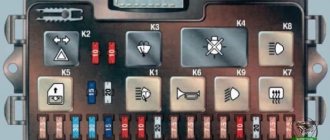
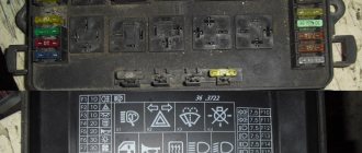
What are the VAZ 2110 fuse box relays responsible for?
K1 – relay for monitoring the health of light bulbs; K2 – front wiper relay; K3 – repeater and alarm relay; K4 – low beam relay; K5 – high beam relay; K6 – additional relay; K7 – relay for turning on the heated rear window; K8 – backup relay (not installed on 110 series vehicles);
F1-F20 in the diagram are fuses. The circuits in the car are protected by fuses based on a certain rated current (in A). The battery charging circuit, generator circuit, ignition and engine starting are exceptions.
To replace a faulty fuse, first find the one that has blown, then eliminate the reason why it was damaged and then install a new one. Below is a list of fuses and information on each one.
* Never replace fuses with jumpers, this can lead to failure of various components and elements, including failure of the wiring tracks in the fuse box and even a car fire.
Standard version of the brake light operating diagram
Power is supplied to fuse F17 from the battery, then the current goes to limit switch contact 11, and then, if the limit switch is closed, a circuit is formed with the filament of lamps 7. But note: part of the circuit is relay K1, more precisely, its contacts 5 and 4.
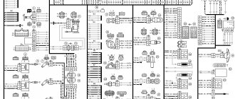
Basic network diagram
A complete electrical diagram with explanations of the VAZ-2112 car is here.
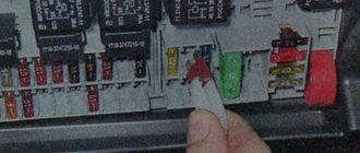
If the brake lights do not light up, on the VAZ-2112, as on all Tens, check one fuse. It is called F17 and is located in the mounting block to the left of the driver.
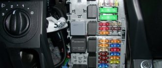
Main mounting block
It is important to know: voltage is always present at one of the fuse terminals. Check it out!
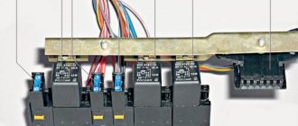
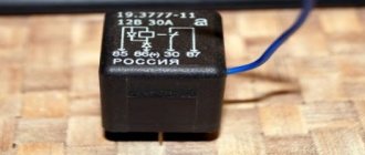
A few words about the “serviceability relay”
The lamp health relay is called K1, and it is the largest in the mounting block. If you remove this relay, then when you press the pedal you can dial the voltage at terminal 5 (but not 4). Look at the diagram again, and it will become clear what we are talking about.
The largest relay in the block
All relay contacts are numbered. Check the voltage at the block terminals:
- 6 – “mass” potential;
- 2 – voltage “+12”, but only after turning on the ignition;
- 5 – “+12” by pressing the pedal;
- 4 – the terminal rings like a ground tap.
If the potential “0” is not generated at terminal “4,” it means that the lamp filaments are burnt out or there is a break in the wiring. Now consider something else: the ground potential has been detected, but the lamps do not light. This is where suspicions of a short circuit arise.
What are the fuses on the VAZ-2110 responsible for?
Decoding fuses.
| Number | Current strength, A | Description of fuses |
| F1 | 5 | License plate lamps. Instrument lighting lamps. Side light indicator lamp. Trunk light. Left side marker lamps |
| F2 | 7,5 | Left headlight (low beam) |
| F3 | 10 | Left headlight (high beam) |
| F4 | 10 | Right fog lamp |
| F5 | 30 | Door window motors |
| F6 | 15 | Portable lamp (socket) |
| F7 | 20 | Engine cooling fan electric motor. Sound signal |
| F8 | 20 | Rear window heating element. Relay (contacts) for turning on the heated rear window |
| F9 | 20 | Recirculation valve*. Windshield and headlight cleaners and washers ( wiper fuse ). Relay (coil) for turning on the rear window heating |
| F10 | 20 | Spare |
| F11 | 5 | Starboard side marker lamps |
| F12 | 7,5 | Right headlight (low beam) |
| F13 | 10 | Right headlight (high beam). High beam warning lamp |
| F14 | 10 | Left fog lamp |
| F15 | 20 | Electrically heated seats. Trunk lock lock |
| F16 | 10 | Relay-breaker for direction indicators and hazard warning lights (in hazard warning mode). Hazard warning lamp |
| F17 | 7,5 | Interior lighting lamp. Individual backlight lamp. Ignition switch illumination lamp. Brake light bulbs. Clock (or trip computer) |
| F18 | 25 | Glove box lighting lamp. Heater controller ( heater fuse ). Cigarette lighter fuse for VAZ 2110, VAZ 2111, VAZ 2112. |
| F19 | 10 | Locking door locks. Relay for monitoring the health of brake light lamps and side lights. Direction indicators with warning lamps. Reversing lamps. Generator excitation winding. On-board control system display unit*. Instrument cluster. Clock (or trip computer) |
| F20 | 7,5 | Rear fog lamps |
Latest news about Lada Vesta Cross
Nowadays, AvtoVAZ produces cars of a completely different level of comfort and reliability, just like the Lada Vesta car model range: modern appearance of the sedan, a variety of body colors, a variety of configuration options, a thoughtful interior and modern electronics. If over the course of several years they have managed to get used to the sedan, then many people are looking forward to the Lada Vesta Cross model and are monitoring the emergence of new information.
Help, fuses are constantly burning. What is the reason?
- How to install a remote fuse for the stove in 2110? – 2 answers
- The engine stalls when driving 2110 - 2 answers
- Electrical equipment failed in VAZ 2110 - 2 answers
- Turn signals and emergency lights do not light up on VAZ 2110 - 2 answers
- Where are the fuses for the VAZ 2110? – 1 answer
Well, there could be quite a few reasons. To begin with, it would be nice to find out which one is burning. If you don’t know, the VAZ 2110 fuse diagram will help. And so.
Possibly a bad contact in the fuse box is to blame; it needs to be tightened.
Maybe there is a short circuit somewhere in the wiring or moisture gets in, then you need to call and look for the unfortunate place.
Another reason may be that one preload is loaded with many electricity consumers, and it cannot cope with the load.
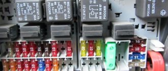
Circuits protected by additional fuses (all fuses are 15 A) on the VAZ-2110:
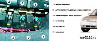
Additional fuses: 1 – ignition module, controller; 2 – canister purge valve, vehicle speed sensor, oxygen (heating) sensor, air flow sensor; 3 – fuel pump relay, fuel pump, injectors.
Additional relays: 4 – electric fan relay; 5 – electric fuel pump relay; 6 – main relay (ignition relay).
There is a fog lamp fuse installed in the niche of the instrument panel behind the mounting block:
Reasons for premature failure of fuses
- A natural factor is the duration of operation without intermediate prevention,
- Moisture ingress, condensation formation, terminal oxidation, insulating layer drying out, electrical supply circuit breakage,
- Mechanical damage, accident, shock, collision,
- Damage to the car fender, windshield, which contributed to damage to the mounting block,
- Short circuit in the electrical supply circuit,
- Exposure to ultraviolet rays.
If after replacing the modules the equipment does not work, then the power supply circuit line is most likely damaged. In the worst case scenario, part failure. Carefully inspect the wiring sections from the battery, generator, starter to the relay switch.
The operating instructions for the technical means indicate the interval before replacing the modules of the mounting block is 40,000 km. In practice, the resource is 5 – 7 thousand km longer.
To prevent premature wear of modules, systematically check the condition of the wiring insulation, the quality of fixation of the terminals, and remove oxidation with fine sandpaper.
As consumables, purchase original domestically produced parts. Check the catalog numbers with the data specified in the instruction manual. Imported analogues are comparable in quality to the Russian manufacturer, but the price is twice as expensive
Table of external connections and connectors of the VAZ-2110 mounting block.
| Block | № | Color | Electrical circuits |
| Ш1 | 1 | ZhCh | fog lamp (left) |
| 2 | GP | trunk lock motor, heated seats | |
| 3 | R | door lock relay | |
| 4 | ABOUT | power window relay | |
| 5 | ZhP | fog light relay | |
| 6 | AND | fog lamp (right) | |
| 7 | MS | power window relay | |
| 8 | — | reserve | |
| Ш2 | 1 | — | reserve |
| 2 | — | reserve | |
| 3 | — | reserve | |
| 4 | H | weight " - " | |
| 5 | ZhP | size (left rear) | |
| 6 | Warhead | outdoor light switch | |
| 7 | — | reserve | |
| 8 | ZhCh | license plate lamps, off instrument lighting | |
| 9 | KP | size (right rear) | |
| 10 | TO | size (right) | |
| 11 | ZhG | email windshield wiper motor, windshield wiper and washer switch. | |
| 12 | Z | outdoor light switch | |
| 13 | ABOUT | fog light switch | |
| 14 | Emergency | hazard switch | |
| 15 | — | reserve | |
| 16 | GP | Ignition switch (terminal 15), steering column switch | |
| 17 | R | windshield wiper and washer switch | |
| 18 | JV | steering column headlight switch | |
| 19 | — | reserve | |
| 20 | — | reserve | |
| 21 | AND | size (left) | |
| Ш3 | 1 | midrange | low beam (left headlight) |
| 2 | — | reserve | |
| 3 | WITH | low beam (right headlight) | |
| 4 | R | generator (cl. 30) | |
| 5 | TO | generator (cl. 30) | |
| 6 | TO | generator (cl. 30) | |
| Ш4 | 1 | PZ | on-board display system |
| 2 | GO | hazard switch | |
| 3 | IF | hazard switch | |
| 4 | H | weight " - " | |
| 5 | PG | portable lamp plug | |
| 6 | Salary | heated rear window switch, heated rear window lamp | |
| 7 | — | reserve | |
| 8 | — | reserve | |
| 9 | — | reserve | |
| 10 | ZhZ | steering column washer and windshield wiper switch | |
| 11 | B | email windshield wiper motor | |
| 12 | BW | steering column washer and windshield wiper switch | |
| 13 | GB | steering column switch, ignition switch lamp | |
| 14 | BP | brake lights, clock, interior lamp | |
| 15 | P | brake lights | |
| 16 | RP | off brake lights | |
| 17 | ABOUT | generator (cl. 30) | |
| Ш5 | 1 | AF | high beam (left lamp) |
| 2 | JV | rear window heating element | |
| 3 | G | heater controller, glove compartment lamp | |
| 4 | Z | high beam (right lamp) | |
| 5 | ZhG | Windshield wiper motor, SAUO recirculation valve | |
| 6 | PB | email cooling fan, beep |
Guides
- Car manuals, instructions, repair and operation manuals for cars 55 views
- BMW error codes 48 views
- Mercedes error codes 47 views
- VW Car Repair and Operation Manual 30 views
- Location of diagnostic OBD connector in FORD 29 views
- Toyota car repair and operation manual 27 views
- Repair and operation manual for Fiat cars 25 views
- Fuse and relay block Citroen Jumper, Fiat Ducato, Peugeot Boxer from 2006 to 2014 25 views
- Fuse and relay box Honda Civic from 2006 to 2011 24 views
- Mercedes car repair and operation manual 24 views
Functions
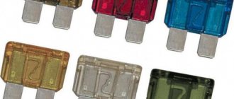
The fuse of the radio, located in the power circuit, is designed to protect the electronic components of the equipment from the consequences of short circuits. The device is a thin thread of low-melting metal, designed to carry a certain current value. As the value increases, the element heats up and subsequently melts. The process takes place in a short time, which allows you to maintain the player’s electronics and the insulation of power cables in good condition.
The thread is soldered to the legs, all elements are housed in a transparent plastic case. The color of the plastic allows you to determine the rating of the fuse link; the digital value is applied to the end part with white or black paint. A fuse of this type is called a blade fuse and is installed in the mounting block in spring contacts that protect the product from falling out.
Where is
The fuses located in the instrument panel to the left of the steering column casing are responsible for protecting the power circuits on VAZ-2110 cars. The top of the unit is closed with a decorative cover, which is secured with a spring clip. To access the fusible links and relays, you need to press the button located under the rotary control for the headlight range control. The decorative casing folds down along with the mounting plate and the protective and distribution devices. On VAZ-2112 and 2111 cars, blocks are used that differ in the number and location of the relays.
Also inside the mounting block are special plastic tweezers and spare inserts. To replace the fuse, the part should be grabbed tightly with tweezers and then carefully pulled out of the socket. The new part must have an identical value; the use of homemade inserts made of wire or foil is strictly prohibited.
The use of fuses designed for high current strength is not allowed, as this may cause the wiring to heat up and the vehicle to catch fire.
Since the cars of the “tenth” family were not equipped with a standard head unit, the installation of radio tape recorders was carried out at dealership centers or by the owners themselves. Since the head acoustic device is a consumer of electric current up to 10-15 A, it is switched through the most powerful fuse. In most cases, this was done using a fuse link designed to protect the cigarette lighter circuit and heater controller. The device has a rating of 25 A, located in the bottom row in the third position from the right.
This switching scheme speeds up installation, but is not correct, since there is a risk of overloading the radio or burning out the insert due to the simultaneously operating head unit and cigarette lighter. It is recommended to connect the radio directly to the battery; a 10-15 A fuse is located inside the power cable.
To protect the battery from discharge, the circuit passes through the ignition switch; a cord with red insulation is used for switching.
When the engine is turned off, the radio does not work, but voltage is supplied (through a yellow insulated cable) to save the settings.
The head unit contains a blade-type fuse rated at 5-15 A (depending on the equipment modification). The element is placed either next to the ISO standard connection block, or inside the wiring harness that comes with the radio. To replace an element, you need a player from a standard socket; for this, special hooks are used that press out the spring clamps.
After installing a new element, it is recommended to check the functionality of all devices involved in the circuit section. If the fuse blows again, the cause of the malfunction is a short circuit in the electrical wiring or inside the head unit. A tester is used to check the condition of the wires; it is recommended to send the radio to a service center for diagnostics and repair.
Functions
A blade-type fuse is a wire designed to carry a certain amount of current. If the parameter is exceeded, part of the element is heated and melted, which allows the power circuit to be broken.
To install the part in the mounting block, flat rectangular legs are used, which are clamped with spring contacts. Metal parts are placed in a plastic case; the color of the material depends on the product rating. The body is transparent, which allows you to visually assess the condition of the fuse thread.
Trouble-shooting
Having established the reason why the VAZ cigarette lighter and radio are not working, we correct the detected breakdown. The list is given in accordance with the listed faults.
- We remove the fuse box (the hatch on the left side of the steering column of the car). We remove the device marked F4 (20 ampere fuse), test it for serviceability with a simple screwdriver probe, if this moment is not visually determined. And we replace it with a new one from the mandatory kit for such cases.
- Check the conductivity of the contacts with a probe. If they are loose, tighten them.
- Strip or resolder the contacts, depending on the situation.
Paradoxically, a burnt-out light bulb breaks the contact circuit (a kind of fuse). Replace it with a working one of the same power.
A short circuit most often occurs due to a loose cigarette lighter socket and a malfunction of its heating coil. If you have the opportunity, then replace them with new ones or restore them to proper condition.
Expert advice
Professional automotive electrical repair technicians complain that even when carrying out repairs that are so insignificant in scope and complexity on their own. Some car owners manage to violate basic rules, thereby significantly aggravating the problem and transferring it to another, more complex (and expensive) repair category.