6.1.8 Checking the fuel pump relay
Service and operation
Manuals → GAZ → 31105 (Volga)
The fuel pump relay is located in the relay board, location 4, on the driver's side under the instrument panel assembly. It must be checked if the pump does not work.
| Reserve | Right headlight (high beam) | Left headlight (high beam), high beam indicator lamp | Right headlight (low beam), electric corrector | Left headlight (low beam) | Electric fan relay (ZMZ-4062 engine), seat heating relay, parking brake warning lamp relay, windshield washer jets | Reserve | Cigarette lighter, horns, horn relay | Rear fog lights | Radio | Engine control unit | Glove compartment lamp, interior lamp, engine compartment lamp | Windshield wiper, headlight washer relay | Front fog lights, rear fog lights | Heater, rear window defroster, rear window defogger relay, auxiliary heater | Reversing lights, instruments, speedometer sensor | Brake light lamp, portable lamp socket | Hazard warning lamp | Left headlight (side light), fog light relay, side light warning lamp | Heated rear window, courtesy lamps, searchlight | Reserve | Electric fuel pump (engine ZMZ-4062) | Engine control system unit (ZMZ-4062 engine) or EPHH unit (ZMZ-402, ZMZ-4021 engines) | Turn signals, side repeaters, breaker, turn signal warning lamp | Seat heating | Right headlight (side light), headlight cleaner relay, trunk light, license plate light, instrument light, cigarette lighter light, medical sign light |
| EXECUTION ORDER |
| 1. Remove the fuel pump fuse No. 28. |
| 2. Connect a diode test lamp using an auxiliary wire between ground and one of the two contacts of the fuel pump fuse. |
| 3. Remove the upper trim in the area of the driver’s feet, on the left, and refer to the subsection Removing and installing the pocket on the driver’s side. |
| 4. Turn on the starter. You should be able to hear the fuel pump relay turn on. In addition, the diode control lamp should light up. |
| 5. If the relay does not turn on, check the supply voltage and control. |
| 6. If the diode control lamp does not light up, although the relay turns on, repeat the test on another fuse contact. |
| 7. If the diode warning lamp does not light again, check the wire between pin 23 of the relay, location 4, and the fuel pump fuse. If there is a break, repair it. |
| 8. If relay power, control, and relay wires are OK, replace the fuel pump relay. |
| Power check |
| Remove the fuel pump relay from the relay board (relay location #4). |
| Turn on the ignition. |
| Connect a voltmeter in series: – between pin 19 (plus of the ignition switch) and ground; – between pin 17 (battery plus) and ground. Required value: 12 V (battery voltage). |
basic information
Fuses in a UAZ car The loaf is located in a special mounting block, which in turn is located in the air supply box on the left side of the vehicle. The mounting block includes all the most important sections of electronic circuits, while supplying them with the necessary fuses and relays. Fuse box of the UAZ Loaf car consists of two lines with fuses and this entire structure is secured with a nut to the vehicle body. If you decide to remove the fuse lines, you will need to disconnect the battery.
The main elements of the electronic circuit include:
- Accumulator battery;
- Electronic fuel pump;
- Fuel mixture purification filter;
- Injectors;
- Engine control unit;
- Electronic ignition coil;
- Spark plugs;
- Idle speed sensor;
- Crankshaft sensor;
- Air damper sensor;
- Tachometer;
- Fan motor cooling the radiator;
- Electronic fan motor control relay;
- An indicator that monitors engine performance;
- Diagnostic connector.
Wiring diagram UAZ Loaf
If any failure of electronic equipment occurs, the current in the node that is responsible for this device will increase, resulting in a short circuit. The wire through which the current passes to the fuse burns out and melts, as a result of which the circuit breaks and the device turns off, but its integrity is maintained. That is, thanks to fuses, the main parts are protected from overheating in the event of a short circuit.
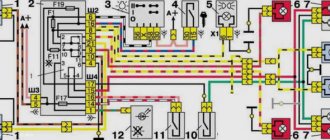
Electrical diagrams of GAZ-3110 "Volga"
(clickable)
(clickable)
| 3. Insert the fuel pump fuse. |
| 4. Install the pocket in the area where the legs are located, and refer to the subsection Removing and installing the pocket on the driver’s side. |
| Fuse no. |
Protected vehicle circuits
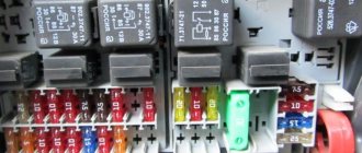
Color coding of flat blade fuses:
| 1 | 25 | Air conditioning fan |
| 2 | 15 | High beam right headlight |
| 3 | 15 | Left high beam headlight, high beam headlight warning light |
| 4 | 10 | Low beam right headlight, electric headlight adjustment |
| 5 | 10 | Low beam left headlight |
| 6 | 10 | Electric fan relay (ZMZ-406), seat heating relay, parking brake warning relay, windshield washer jets |
| 7 | 20 | Spare |
| 8 | 20 | Cigarette lighter, horn relay, horns |
| 9 | 15 | Rear fog light |
| 10 | 10 | Radio equipment (radio tape recorder, electrical antenna circuits) |
| 11 | 5 | Engine control system unit (ZMZ-406) |
| 12 | 15 | Engine compartment lamp, glove compartment lamp, interior lamp |
| 13 | 10 | Wiper |
| 1 | 25 | Front fog lights, rear fog lights |
| 2 | 15 | Heater fan electric, rear window defroster relay, rear window defroster |
| 3 | 15 | Reversing light, instruments, speedometer sensor |
| 4 | 10 | Brake lights, portable lamp socket, additional brake light |
| 5 | 10 | Alarm |
| 6 | 10 | Left side lights, fog light relay, side light indicator |
| 7 | 20 | Heated rear window, courtesy lights |
| 8 | 20 | Electric exterior mirrors and door locks |
| 9 | 15 | Electric fuel pump (ZMZ-406) |
| 10 | 10 | Engine control system unit (ZMZ-406) or EPHH unit (ZMZ-402) |
| 11 | 5 | Turn signals, repeaters, breaker and turn signal indicators |
| 12 | 15 | Seat heating |
| 13 | 10 | Right side lights, trunk lights, license plate lights, instruments, cigarette lighter |
| 5A - orange | 10A - red | 15A - blue | 20A - yellow | 25A - white |
Under the hood, on the left mudguard there is a block of two fuses for 30A and 60A.
30A - protection circuit of the electric cooling fan, 60A - all other circuits except the starter. But the starter relay contacts are protected. See diagram.
Where is the charging relay located?
The charging relay consists of a reverse current relay, a regulator and a limiter. The reverse current relay turns the generator on when its voltage increases, and turns it off when the battery voltage increases.
The regulator controls and limits the current within 13.8 - 14.8 V, and regulates the charging current. The limiter protects the generator from overloads, working on a similar principle to the voltage regulator - it includes additional resistance in the winding circuit as the current increases.
The charging relay works in conjunction with the alternator under the engine hood on the right side.
Technical characteristics of the electronic relay-interrupter and alarm system RS950P.
— Rated voltage, V: 12 — Switched load in turn signal mode, number and power of lamps in W: 3х211х5 — Switched load in alarm mode, number and power of lamps in W: (3х211х5)х2 – Interrupt frequency, cycles per minute: 60-120 — Electrical connection design: two pin blocks, analogues 502608 and 502606 OST 37.003.032, plug 6.3 — Overall dimensions: 41х120х98 — Weight, kg: 0.1
Similar chapters from other books
External glass and porcelain insulation of electrical equipment and switchgear
External glass and porcelain insulation of electrical equipment and outdoor switchgear Question. How should the specific effective creepage distance of external porcelain insulation, as well as insulators of flexible and rigid external open conductors, be selected? Answer. Must be selected based on data
Placement and installation of electrical equipment
Placement and installation of electrical equipment Question. What electrical equipment and devices can be installed in EMF? Answer. Can be installed: electric machines; electric machine converting units; starting and control devices for
Placement of electrical equipment
Placement of electrical equipment Question. What conditions must the placement of electrical equipment of adjustable electric drives satisfy? Answer. Must satisfy the general requirements set out in chapters 4.3, 5.1, 5.3 of these Rules, as well as the technical specifications for
Classification and marking of explosion-proof electrical equipment according to GOST 12.2.020-76
Classification and marking of explosion-proof electrical equipment according to GOST 12.2.020-76 Question. What are the established explosion protection levels for electrical equipment? Answer. The following levels have been established: electrical equipment of increased reliability against explosion - explosion-proof
Electrical faults
Malfunctions of electrical equipment The battery requires attention The battery discharges slowly during operation. The starter cranks the engine at a low speed. Current leakage through damaged insulation of any wire or device - from here
4.3.1. General overview of motivational processes in quality management
4.3.1. General overview of motivational processes in quality management The concept of “motive” is often used to denote such psychological phenomena as aspiration, desire, intention, fear, etc., which are reflected in a person in the form of readiness for activities leading to
Military options and equipment on the UAZ-469 vehicle
Military options and equipment on the UAZ-469 car With the start of serial production, the UAZ-469 immediately became the main light multi-purpose vehicle of the Soviet Army and the armed forces of all fraternal and allied countries. In the 1970s, it was exported to 70 countries. These cars were
General information about the car
General information about the car Below are the main technical data and presented in the form of logical diagrams operational methods for troubleshooting the latest modernized model of the Volga GAZ-3110 car with a sedan body and with a ZMZ-402 engine,
Where is the turn signal relay located?
In UAZ vehicles, the turn signal circuit includes a steering switch, a turn relay, an hazard warning light and six bulbs.
This system is protected from overloads by several fuses:
- F8 – 10 A (for alarm);
- F20 – 7.5 A (for direction indicators).
Turn signals without a relay will not blink, so its malfunction is easy to determine.
It is located in the mounting block, on the left side, at the driver’s feet. In ambulances and utility vehicles of the UAZ type, the turn relay is installed on the partition, behind the driver's seat.
If the relay malfunctions, it must be removed, and the use of metal objects is not allowed.
On modern cars, instead of traditional electrothermo-mechanical relays, electronic relay-interrupters for direction indicators and hazard warning lights, made on the basis of microcircuits or discrete elements, are used.
Electronic relay-interrupters RS950P and 494.3747 for direction indicators and hazard warning lights provide an intermittent signal from the direction indicator lamps of vehicles in the maneuvering and emergency signaling mode, and monitor the serviceability of the direction indicator lamps in the maneuvering mode.
Replacing wiring
Wiring for a Gazelle 406 engine with pinout of ECU connector terminals.
Changing all the electrical wiring of a Gazelle when replacing an engine from 402 to 406 is of course not impractical.
The fact is that on newer versions of Gazelles, the connection diagram of certain devices also changed:
- Gazelle 406 wiring is integrated into the standard electrical system in the engine compartment;
- electronic components and control devices are connected using terminals;
- The voltage and correct connection are checked using testers.
After assembling the wiring into a single whole, its functionality is checked. Subsequently, the operation of the power unit is adjusted.
Conclusions: Replacing the power unit inevitably affects the change in the standard electrical wiring of the car
That is why it is important to have a visual aid at hand when carrying out such an operation, and the Gazelle’s factory wiring diagram will allow you to avoid mistakes
Features of electrical equipment
The GAZ electrical equipment diagram includes the following subsystems:
- engine starting system;
- ignition, which includes a distributor, spark plugs, coil, etc.;
- external car lighting, including fog optics, light alarms and turn signals;
- dashboard;
- interior lighting, as well as all devices installed in it;
- heating system - stove;
- windshield wiper unit;
- headlight adjustment device;
- microprocessor-based engine control system;
- mounting block of safety devices.
Photo gallery “Subsystem connection diagrams”
Fuse box
On a GAZ 3110 car, the fuse box is located on the instrument panel on the passenger side. It is designed extremely simply - it consists of two blocks with fuses of 10.15 and 20 Amps.
This is what the fuse box for GAZ 3110 looks like
The unit is conveniently located and changing fuses is very easy. And unlike the Zhigulevsky, the fuse box is very cheap.
Return to contents
GAZ 3110 Volga sedan (GMOD SMR SCARS) by DigitalExplorations on DeviantArt
Ported from one of the larger GMOD Russian SCARS packages that exist. The original source is unknown, but variations of this model can be found on many free 3D model sites on the Internet. As with many GMOD SCARS models, you can change the color or texture of the body by simply replacing the "skin" texture.
The GAZ 3110 Volga turned out to be the most successful of the second generation of Russian sedans of the GAZ 31 series and the first truly popular car in the GAZ 31 line. It was still borrowed from the time-tested GAZ 24, like the entire GAZ 31 series, from which it inherited name Volga, but it was improved as much as its old but reliable frame and design could be. With a completely new modern body design, a truly comfortable interior (which was new for Russian cars at the time, as they will tell you), a decent transmission and modern suspension, and at a price that is affordable for most working Russians, in fact
itself (especially the low-end budget version, only for base models), it turned out to be much better than expected. It was seen as an inexpensive alternative to expensive imports from Europe and America, and even performed well on the resale market. It was also available in both petrol (petrol) and diesel models straight off the production line. Its only shortcomings were those that affected all Russian-built cars in the 1990s: poor assembly, faulty electronics and poor service from the manufacturer. However, the time for change was approaching the classic Volga family, and it was clear that the basic design had almost reached the limits of possibility of modification. There would be another attempt to make a modern Volga (GAZ 31105), but that was all. The GAZ 3110 sedan ceased production in 2004, although a station wagon or station wagon version will remain in production until 2010.
To download, click the "Download" button in the upper right corner.
.
Where is the gas turn relay 31105 located?
Gas 31105 cars with Chrysler engines plus restyling were considered.
fuse box in the cabin.
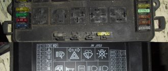
In cars manufactured before May 2007, the fuse box is located above the glove compartment behind a plastic cover. To access the fuses, you need to slide the cover with the word “Volga” to the right, then insert your finger into the opened hole and pull the cover towards you to remove it.
diagram of the location of fuses in the cabin block (until May 2007)
Left block fuses
Heater electric motor (air conditioning)
Main beam of the left headlight, indicator lamp for turning on the main beam of headlights
Cigarette lighter, horns, horn relay
Fuel pump, exhaust oxygen concentration sensor
Turn signals, turn signal relays, turn signal warning lamps
Engine compartment lamp, glove box and interior lamps
Right block fuses
Heating (air conditioning) and ventilation control unit, rear window heating relay, rear window heating (1 mode)
Reversing light, speed sensor, instrument cluster, cooling motor relay
Left side lights, side light warning lamp, fog light relay
Heated rear window (mode 2) and mirrors
Anti-lock brake system (ABS)
READ Where is the light fuse on Kalina
Electric drives and heated exterior mirrors
Right side lights, headlight washer relay, trunk light, license plate lights, instrument lights, cigarette lighter, switches. Electric headlight corrector
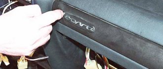
In Gas 31105 (Chrysler) cars produced after May 2007, the fuse box is located under the instrument panel behind the cover.
To access the fuses, remove the decorative cover.
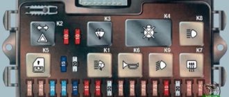
diagram of the location of fuses in the block.
Upper block fuses
Heater (air conditioning) electric motor
High beam of the left headlight, indicator lamp for turning on the high beam of the headlights
Low beam of the left headlight, indicator lamp for turning on the low beam of headlights
Cigarette lighter, horns, horn relay, instrument cluster clock
System, engine control, diagnostic connector
Turn signals, relays , turn signal warning lamps
Engine compartment lamp, glove box and interior lamps
Lower block fuses
Heating (air conditioning) and ventilation control unit, heater valve, central light switch, front lamp, interior temperature sensor, fog lamp relay
Reversing light, speed sensor, instrument cluster
Left side lights, control pump for turning on side lights
Anti-lock brake system (ABS)
Right side lights, trunk light, license plate lights, instrument lighting pumps, cigarette lighter switches Electric headlight corrector
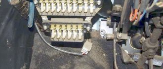
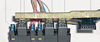
Relay unit in the passenger compartment Gas 31105 (Chrysler).
- starter relay;
- relay for turning on fog lights;
- rear fog light relay;
- relay - windshield wiper breaker;
- relay for low beam headlights;
- headlight high beam relay;
- relay for turning on sound signals;
- relay for switching on electric heating of rear window glass
Turn signal relay.
located on the turn switch.
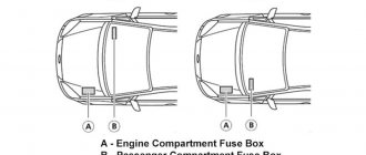
Fuse box in the engine compartment Gas 31105 (Chrysler).
where it is located - on the left mudguard under the hood.
diagram of the location of fuses in the block.
60 A protects the anti-lock brake system (ABS) circuit;
at 60 A - almost all power supply circuits for vehicle consumers, except for the starter circuit and those protected by the rest of the fuses in the unit; fuse
40 A - power supply circuits for vehicle lighting and light signaling;
90 A - circuits of the battery, generator, electric headlight washer (if equipped) and the power circuit of the electric radiator fan of the engine cooling system.
On vehicles not equipped with anti-lock brakes and manufactured before July 2006, the fuse was not used.
Since July 2006, through this fuse, terminal “A29” of the engine control unit has been connected to the generator, through which the function of controlling the excitation current of the generator is carried out (voltage adjustment in the vehicle’s on-board network).
Fuel pump relay and main relay of the engine management system.
located under the hood on the cooling system tank mounting bracket.
The relays on the left are located on the left mudguard.
- radiator electric fan relay for the engine cooling system,
- fuel injection system relay,
- air conditioning fan relay,
- The air conditioning compressor clutch relay is located on the left mudguard of the engine compartment and is attached to the power steering reservoir mounting bracket.
An electronic turn signal switch type 494.3747, or 642.3747, or 232.3747 is installed in a relay , covered by a decorative side panel on the left side under the instrument panel. During operation, the breaker does not require maintenance. The breaker cannot be repaired, and if it fails, it must be replaced. The relays in the block do not have fixed mounting points. When searching for the required relay, focus on the number and colors of wires, comparing them with the car’s electrical diagram (see Appendix)
If it fails, we recommend replacing the relay assembly, since if the winding is burned out or the relay contacts are severely burned, it is difficult to properly restore its functionality.
Unscrew the four screws 1 and remove the left trim 2 of the front side panel.
Label and disconnect the wires from the relay terminals. Unscrew the fastening screw and remove the relay.
The electronic turn signal switch type 494.3747, or 642.3747, or 232.3747 is installed in the relay block, covered by a decorative side panel on the left side under the instrument panel. During operation, the breaker does not require maintenance. The breaker cannot be repaired, and if it fails, it must be replaced. The relays in the block do not have fixed mounting points. When searching for the required relay, focus on the number and colors of wires, comparing them with the car’s electrical circuit diagram.
If it fails, we recommend replacing the relay assembly, since if the winding is burned out or the relay contacts are severely burned, it is difficult to properly restore its functionality.
Unscrew the four screws 1 and remove the left trim 2 of the front side panel.
Label and disconnect the wires from the relay terminals. Unscrew the fastening screw and remove the relay.