Opel Vectra C (Opel Vectra c) the third generation of the Opel Vectra model range. Vectra c produced in 2002, 2003, 2004, 2005, 2006, 2007, 2008. The luxury model Opel Signum was subsequently built on its basis. In this publication you will find description of fuse and relay blocks Opel Vectra C, with diagrams blocks and photographs. Let's highlight the fuse responsible for the cigarette lighter.
The design of the blocks and the purpose of the elements in your Opel Vectra may differ and depend on the year of manufacture, the level of electrical equipment and the country of delivery.
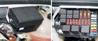
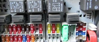
Relay and fuse box in the interior of the Opel Vectra C (Signum)
The block is located at the end of the instrument panel on the driver's side. To gain access, you must remove the plastic cover.
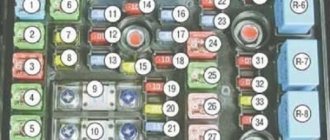
Fuse box diagram for Opel Vectra C/Signum
Relay block diagram Opel Vectra C/Signum
Description
| 1 2 | Main ignition circuit relay (terminal 15A) Terminal 15 relay |
| 3 | Cabin ventilation relay |
| 4 | Heater Fan Motor Relay |
| F1 | (20A) Audio system, additional heater, DVD player |
| F2 | (7.5A) Air Conditioning - Manual Temperature Control, A/C/Heater Fan Motor |
| F3 | (20A) Hatch |
| F4 | |
| F5 | (7.5A) Door electrical control unit |
| F6 | (7.5A) Brake lights |
| F7 | (30A) Multifunction control unit 1 |
| F8 | (30A) Door electrical control unit |
| F9 | (7.5A) Multifunction control unit 1 |
| F10 | (7.5A) Steering column electrical control unit |
| F11 | (7.5A) Diagnostic connector (DLC) |
| F12 | (15A) Battery overload protection |
| F13 | |
| F14 | |
| F15 | (30A) Driver's door electrical control unit |
| F16 | |
| F17 | (15A) Instrument cluster, multifunction display |
| F18 | (7.5A) Ignition switch, air conditioning |
| F19 | |
| F20 | (7.5A) Lateral movement sensor |
| F21 | (7.5A) Telematics |
| F22 | (30A) Cigarette lighter fuse opel vectra c/signum |
| F23 | (30A) Air Conditioning - Manual Temperature Control, A/C/Heater Fan Motor |
| F24 | |
| F25 | (7.5A) Air Conditioning - Manual Temperature Control, A/C/Heater Fan Motor |
| F26 | (7.5A) Multifunction display, instrument cluster |
Removal and replacement process
If one of the electrical devices in your car has stopped working, then perhaps the essence of the problem lies in the failure of the link. Of course, the cause of the malfunction may be the device itself, for example, a windshield wiper motor or a malfunction of the headlights. But it makes sense to check the functionality of the power supply element.
To do this, evaluate the part visually. If the fusible thread of the device is broken or burned out, then there should be no doubt: it was he who failed. However, before replacing it, you should make sure that the part will not fail again immediately after its replacement.
PSU for model B at the installation site
To do this, it is advisable to check the functionality of the device whose link has burned out. Perhaps this is the reason. It is also advisable to test the electrical circuit, because there is a possibility that it may have breaks or short circuits. First of all, attention should be paid to areas that have been soldered. Sometimes it is short circuits that can cause regular combustion of power supply elements. If you are sure that the reason lies precisely in the power supply device, then it needs to be replaced. This is done very easily.
- First you need to turn off the ignition.
- Using a screwdriver or your fingers, open the protective decorative cover of your power supply. As you already know, it is located on the left side of the dashboard in the driver's seat area.
- Find the burnt element. To do this, use the diagram marked on the back of the protective cover.
- Using special tweezers, which should be located in the power supply housing, remove the damaged chain link.
- Take the new part and install it in place of the old one. Turn on the ignition and check the functionality of the device that previously failed. If the problem was in the power supply part, then after replacing it everything will work fine. Replace the protective cover of the power supply unit.
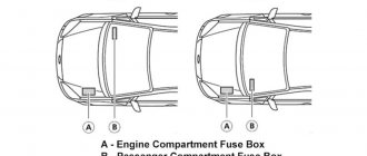
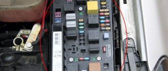
Relay and fuse box under the hood of Opel Vectra S (Signum)
Fuse box diagram in the engine compartment of the Opel Vectra C/Signum
Description
| N9 | Protected circuit | Rated current |
| 1 | ECM/TCM module | 20 A |
| 2 | Starter | 25 A |
| 3 | Sound signal | 20 A |
| 4 | Air conditioning/climate control | 10 A |
| 5 | Window washers | 15 A |
| 6 | — | — |
| 7 | Central control/ESP/TC | 15 A |
| 8 | Headlights | 10 A |
| 9 | Heated washer nozzles | 7.5 A |
| 10 | — | — |
| 11 | Glass cleaners | 30 A |
| 12 | Glass cleaners | 30 A |
| 13 | Central control/ESP/TC | 7.5 A |
| 14 | Headlight washers | 30 A |
| 15 | Lambda probe | 10 A |
| 16 | ABS | 7.5 A |
| 17 | — | — |
| 18 | — | — |
| 19 | Adjusting the headlight angle | 5 A |
| 20 | — | — |
| 21 | — | — |
| 22 | — | — |
| 23 | Heating/ventilation system for the vehicle interior when parked | 20 A |
| 24 | Terminal 30 | 30 A |
| 25 | Terminal 30 | 30 A |
| 26 | — | — |
| 27 | — | — |
| 28 | Rear electrical control unit | 60 A |
| 29 | ABS | 40 A |
| 30 | Rear electrical control unit | 60 A |
| 31 | Interior electrical control unit | 60 A |
| 32 | ABS | 40 A |
| 33 | Interior electrical control unit | 60 A |
| 34 | Rear electrical control unit | 60 A |
| 35 | Cooling fan 1" | 30 A 40 A |
| 36 | Cooling fan 211 | 20 A 30 A |
| 37 | — | — |
| 38 | — | — |
Problems when paying with bank cards
Sometimes difficulties may arise when paying with Visa/MasterCard bank cards. The most common of them:
- There is a restriction on the card for paying for online purchases
- A plastic card is not intended for making payments online.
- The plastic card is not activated for making payments online.
- There are not enough funds on the plastic card.
In order to solve these problems, you need to call or write to the technical support of the bank where you are served. Bank specialists will help you resolve them and make payments.
That's basically it. The entire process of paying for a book in PDF format on car repair on our website takes 1-2 minutes.
If you still have any questions, you can ask them using the feedback form, or write us an email at
Sources
- https://PrideSaratov.ru/obsluzhivanie-avto/shema-predohranitelej-opel-vektra-a.html
- https://venteler.ru/net-predokhranitel-ventilyatora-pechki-vektra-a/
- https://drajver.ru/dvigatelej/rele-ventilyatora-opel-vektra-a.html
[collapse]
Additional block in the engine compartment
The relay block comes in 2 configurations.
Package 1
- —
- Glow plug control unit (60A)
- Fuel filter heater relay (30A)
- Glow plug control unit (60A)
R3 - fuel filter heater relay
Package 2
- —
- Starter (30A)
- —
- Horn (30A)
R2, R3 - fuel heater relay
Heating relay opel vectra c liftback
Opel Vectra C owner's story - electrical and electronics. No. Protected circuit Rated current 1 Infotainment system 20 A 2 Heating, ventilation, air conditioning (HVAC) system 7.5 A 3.
Interior heating, ventilation, air conditioning (HVAC) system. 7.5 A. – – Relay placement in the interior mounting block. No. Working circuit.
History of the logo. The company's logo has changed several times throughout history. During the Nazis' rise to power, the emblem looked like an airship flying through the letter "O". Since 1964, the famous lightning bolt has been established as a logo.
Car: Opel Vectra A 20NE Region: Kremenchug Posts: 764. Re: Heated rear window. Vectravod Offline. Car: Opel Vectra A 2.0i Region: Volnovakha Messages: 104.
Heated rear window I also fiddled with it, it turned out that there was only one strip on the glass. Heating system, interior ventilation, HVAC climate control. Re: Heated rear window I rummaged around the net a little, but there’s nothing complicated, one thread doesn’t work for me, but it’s a pity for the tinting. Re: Heated rear window Hello everyone.
Wiring diagram for heated glass relay – Vectra Club Russia
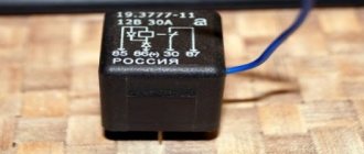
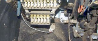
Location of relays and control units on the car: a - location. Plastic fuse housings have different colors to match. Part of the relay is located in the fuse box, and the other is located in a separate additional one.
The relay being replaced is simply pulled out of its socket. Service maintenance and operation. Environmental protection and energy saving. Fuel and exhaust system of models with fuel injection system.
Exhaust system and emission control system. Diesel engine fuel systems. We bring to your attention the address and telephone directory of automobile enterprises.
Fuses, relays and control units. Relay and fuse box. This circumstance allows you to freely use the work, while respecting personal non-property rights - the right of authorship, the right to a name, the right to protection from any distortion and the right to protect the author's reputation - since these rights are protected indefinitely.
All information presented on this site is the property of the project or other indicated authors. Direction indicators in hazard warning mode. Passenger mirror light. Luggage compartment lamp.
Right headlight side light. The right rear marker light. Left headlight side light. The left rear marker light. Right headlight high beam. Indicator lamp for high beam switching on. Left headlight high beam. Right headlight low beam.
Left headlight low beam.
Instrument cluster lighting lamps. Reversing lamps. On-board control system unit. License plate lamps. Glove box lighting lamp.
Windshield wiper motor. Rear window heating element. Sunroof drive motor. Centralized door locking system. Front seat heating elements. Memory device of the electric drive for position adjustment.
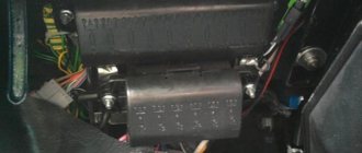
Additional relay box under the instrument panel.
Opel Vectra C GTS 1.8 acceleration / acceleratie 0-100 km/h
- RSS subscription
- Share Vkontakte
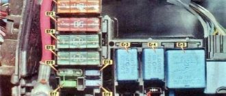
Relay and fuse box in the trunk of the Opel Vectra S (Signum)
Located on the left behind the plastic cover
Fuse box diagram in the trunk of the Opel Vectra C (Signum)
Relay block diagram in the trunk of Opel Vectra C (Signum)
The relays are located on the back of the fuse mounting block.
Description of fuses and relays
| 1 | Rear window wiper relay |
| 2 | — |
| 3 | Rear left seat heater relay |
| 4 | Rear right seat heater relay |
| 5 | Anti-theft horn relay |
| 6 | — |
| 7 | Central locking hatch/fuel filler cap |
| 8 | — |
| 9 | Main ignition circuit relay |
| 10 | Rear window defroster relay |
| 11 | Fuel pump relay |
| F1 | — |
| F2 | — |
| F3 | (40A) Power seat |
| F4 | (40A) Rear window defroster |
| F5 | (40A) Power seat |
| F6 | (30A) Electric window lift - right rear |
| F7 | (30A) Electric window lift - left rear |
| F8 | (15A) Seat heater, rear right |
| F9 | (15A) Anti-theft system, horn |
| F10 | (20A) Fuel pump |
| F11 | (25A) Battery voltage |
| F12 | (12A) Heated seat - rear left |
| F13 | (20A) Trailer electrical connector |
| F14 | (15A) Rear window wiper |
| F15 | (15A) Seat heater, seat ventilation system, front left |
| F16 | (15A) Seat heater, rear right |
| F17 | (15A) Accessory connector |
| F18 | (30A) Trunk/tailgate lock |
| F19 | (10A) Battery voltage |
| F20 | (7.5A) Central locking |
| F21 | (5A) Volume change sensor (anti-theft system) |
| F22 | (30A) Remote trunk lock control |
| F23 | (7.5A) Anti-theft wire on glass (anti-theft glass break sensor) |
| F24 | (25A) Battery voltage |
| F25 | (10A) Suspension control system |
| F26 | (25A)Ignition switch |
| F27 | (5A) Occupant sensor, tire pressure monitoring system, rain sensor, air conditioning system |
| F28 | (7.5A) Parking system sensors |
| F29 | — |
Color marking
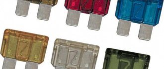
Let's start with color coding, which makes it possible to quickly determine the design parameters of fuses, indicated in amperes. These colors will be used in the future in all diagrams attached to the article.
Knowing the color coding greatly simplifies not only the search for faulty components, but also the selection of a replacement that is suitable for its characteristics.
Important! Do not install fuses whose parameters do not meet the requirements of the developers! This may cause serious malfunction or fire.
Diagnosis of a faulty electrical circuit
When working with a car's electrical circuit, you must turn off the ignition and battery by removing the minus terminal. The main causes of electrical equipment failures:
- Contact faults (oxidation) at connectors
- Open circuit in wiring sections
- Short circuits
- Unstable grounding (poor contact to ground)
- Relay failure or blown fuse
To diagnose a circuit, use a voltmeter or a 12V tester (you can use a simple probe with an indicator), an autonomous power source and a set of wires with alligator clips. First, check the safety of the fuses and the functionality of the relay - the fuse links are inspected visually, the relay should make a characteristic click when voltage is applied. If all fuses are good, then the problem is in the wiring.
Circuit short circuit test:
- All electrical equipment is disconnected from the battery power.
- The circuit under test is tested with a voltmeter in the area from the fuse socket; to do this, remove it from the connector and connect the tester instead.
- Next, turn on the circuit: if the indicator light comes on, then there is a short circuit in this section of the circuit. The reason may be broken insulation on the wiring or dirty contacts.
If there is no voltage (everything is fine with the circuit), but the fuse often blows, this means a malfunction in the operation of the electrical equipment element.
Ground voltage test:
- Disconnect the battery.
- One end of the tester is attached to any grounded (connected to ground) element.
- The second end of the tester wire is connected to a part of the car body, or to the section of the circuit being tested: if the current resistance value is zero, then the ground contact is OK.
If poor grounding is detected, inspect the contacts and battery terminals for corrosion, oxides and contamination. It is worth remembering that the circuit should not have breaks, short circuits or loose connections at the contact points.
Sources
- https://carpod.ru/predohraniteli-opel-vectra-b-1995-2003_2937.htm
- https://zapchasti.expert/predoxraniteli/predoxraniteli-opel-vectra-b.html
- https://avtorom.ru/opel-vectra-b-predohraniteli-i-rele/
- https://remocars.ru/opelman/vectra-b/elektrika/blok-predohraniteley-i-rele-opel-vektra-b.html
- https://vsepredohraniteli.ru/opel/vectra-b.html
- https://avtozam.com/opel/vectra/opisanie-predohraniteley/
OPEL VECTRA (A) 1991
This page will contain everything that I encountered when repairing the OPEL VECTRA A - be it electrical or mechanical. Used it when repairing an Opel - a multimedia manual, eyes and hands.
If one of the turn signals flashes faster than the other?
The reason is that one of the turn signal bulbs burned out.
Heated rear window does not work
The rear window heating terminals are located on the right and left in the middle under the plastic. I rang the filaments - 1.6 Ohms - ok. Next in the trunk there is a wire transition from the filaments to the common wiring harness. Was melted - re-compressed.
To the lower left of the driver's left foot under the plastic there is a block (X6 in the diagram) - I took it apart and checked it with a tester - the black wire between the rear window threads and the block is intact - happily - no need to change.
Next, I checked the wire from this block to the relay - it’s ok.
The red wire from the generator goes to recharge the battery, and the blue and white wire powers the ABS and the rear window heating button - only when the engine is running)) So - there are 14 Volts on these wires. Go ahead.
On the S4 button (pins 4 and 3) in the cabin there is power from F9 and blue and white wiring. The button is removed by carefully prying it from below. Fuses F2 and F15 provide voltage for contacts 15 and 30, when you press the button, power is supplied to contact “E”. Contact “E” is not indicated in the diagram - a white-black wire goes to it.
So - I hit the relay - the last stronghold of the Opel rear window heating not working.
Relay K35 (italamec 512 12V 30A GM 90376957) is located above the clutch pedal (green socket) - two sockets nearby were empty - apparently in the future they will be used for other relays.
This is not written anywhere, I myself traced it from the wiring harness to the relay itself - apparently, so that they contact service workshops.
I took apart this relay. I rang the coil - 86 Ohm (look at the photo above) - it seems to be in order - although maybe the coils are parallel there and give a loop. Most likely we have run out of TYA0298 KONJ – counter. I tried to bridge the 30th and 87th contacts in the socket - the heating worked - I need to buy myself a new relay.
This rear window heating relay is very specific - after driving to several stores and searching on the Internet, nothing was found. We went to disassembly and on the second one we were given a relay from DAEWOO - after all, they have almost everything Opel - they gave us 96116223 - slightly different in numbers from 90376957. We installed it - and lo and behold, it works.
The reason is the 4th fuse in the fuse block. Cleaned the contacts and blew everything out.
We noticed a small stain of gasoline under the car when we left the parking lot.
It turned out that gasoline was leaking near the right rear wheel. Having arrived at the pit, I found out that it was a hose from the pump and a trickle of gasoline was coming out of it. I temporarily wrapped it with a piece of rubber and tightened it with a clamp - the leak went away. Then they replaced the hose.
The handbrake began to tighten poorly
The cable was changed 1.5 years ago. The cable adjustment was at maximum - there was nowhere to turn further. See photo. I already wanted to change the cable - but Dad persuaded me, saying that Opel has another adjustment device - in the brake drum.
This is the spacer device (see photo above) - which is not shown in the manuals, but only the hole for its adjustment is shown (see photo below). We didn’t immediately understand until we removed the drum itself. The most valuable photos for those who have never tried to adjust the hand brakes on an OPEL VECTRA (A) car.
We did this: we loosened the cable over the rear axle (key set to 11) then, jacking up the car and removing the wheel, we adjusted it using a spacer in the drum (with an accuracy of a millimeter) so that the disc rotated freely and did not catch the handbrake pads. Also on the other wheel. Then they tightened the cable over the rear axle (and voila: the handbrake grips well on the fifth click of the ratchet.
When starting a cold engine, the Opel stalls and when changing gears on the highway and pressing the gas pedal, it reacts only after a second
Such failures are gloomy - especially when you go to overtake and the car starts to stop.
We checked the fault codes: we short-circuited the yellow and yellow-brown wires and looked at the check and counted - the connector is under the hood on the driver's side - shown in the photo on the left.
Octane corrector – in the photo it says “91”, changed to “95”, because... I fill it with 98 – green.
The spark plugs are fine and the wires to them are fine.
We checked the SB224 air filter - it needs to be changed - 40 UAH..
At the same time, the injectors were cleaned - 300 UAH.
The symptoms have disappeared - the machine works great.
Open circuit test:
- One end of the wire with the negative terminal of the tester (probe with indicator) is connected to the negative terminal of the battery.
- The second clamp is attached to the end of the circuit being tested, as close as possible to the fuse connector socket.
- The circuit is turned on by using the element of electrical equipment being tested: if the voltage is stable 12V, then the circuit is operational, if there is no power supply, then proceed to checking the next section. It is worth remembering that some electrical appliances turn on only when the ignition is connected (the key position in the ignition switch is “ON”).
The detected faulty section of the wiring is replaced completely along the entire length from the source to the consumer. Often the reason for the lack of voltage is poor contact on the connector due to the formed oxide; it is cleaned with fine-grained sandpaper, wiped dry and the diagnostics are carried out again.