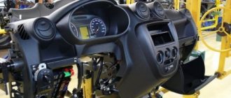
Firstly, you need to look at the ICC pinout in the Grant album - in Kalinovsky there is no diagram for the suite. Here she is:
Secondly, as I wrote earlier, there is a discrepancy in the block and in the contacts, namely, there is no wire to pin 4 of the MUS (pin 7 of the block), but there is a wire to the missing contact 1 of the MUS (pin 1 of the block). Which is strange in itself and doubly strange due to the fact that, according to the diagram, the DRLs are turned on directly from pin 4.
So, thirdly, yesterday I hung out in the garage with friends and a multimeter :) Measurements showed that: - there is no voltage at pin 4 of the MUS with the ignition on, but the engine not running; — on pin 4 of the MUS with the engine running there is +12 V; — on contact 1 of the block when the ignition is on there is +6 V.
I would now like to understand why it was made and how it can be used. Well, also, how do DRLs that are not connected to the MUS connector work?)))
Yesterday we put a net in the bumper, but there are no photos in daylight, so there will be a post later.
Finally got around to installing and connecting the PTFs themselves; more than two months have passed since I ordered and installed the facings. I spared some money and bought for 520 a set for connecting PTF from Antey for Granta 2190 (the wires were long enough everywhere, they even turned out to be a little longer! If you don’t have enough, you are either driving along the wrong highway, or you have a set of Viburnum/Priora). And two auto light-colored PTFs for grants with a convex magnifying glass (plastic), well assembled, two anti-fog channels, that's all... They sell them individually, which is why I had to go to four stores to get a set, because... Basically, only the right ones were sold, and there were no left ones, neither in Strogono, nor at the B.Akademka, nor at Dmitrovka, only at Korovinsky I bought a pair for 1767 in today’s money gud, in Auto49 they have now become cheaper, they cost 1150 apiece, and so 883.5 one comes out, I wanted to order it on the drivebox for 750 a piece, but with delivery it will be even more expensive. Mus took from Granta Luxova 2190-…-20 for 950 in Saburovo.
The whole process seemed more difficult and more tedious to me than installing the alarm myself. This is if you implement PTF indication on the gearbox/speedometer, fuses in standard places, relays in the mounting block, and then all this is installed through the mus, and not an additional button from which you also need to run wires, and our standard bumper is not like in a sedan grants, whose glasses for PTF still need to be cut, I installed the trims here and use three self-tapping screws to screw the fog lights into the mounts in the standard places. BUT this sex is worth it, everything was fully realized as I wanted, the light is cosmically added to our headlights, after 12 there is generally sunshine and all this cost me a little more than 3000 rubles. Dealers in Moscow are asking 10 thousand for installation with materials, and then without luxury musa (just through a button), without an indication on the speedometer, but with the bonus of twists with electrical tape, a hole in the hydrocorrector plug, collective farm-cut linings, snot, cut wires and a mined car, which will then certainly begin to smoke starting from the mounting block. Therefore, if you love your car and have experience and flexible hands, then do everything yourself with high quality and not expensive.
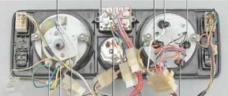
1. Analysis of the parts, lay everything out on the table, everything is done well, the main harness is even corrugated, the wires are solid, in some sets everything is connected through two or three blocks to the mounting block, but here everything is monolithic with a standard length. We don’t need the button with its block and winding, the hinged block was also not useful, I put the relay in the mounting block in place of the K2 relay, where in other configurations there is a power window relay, and I took the block and put it under the trunk release relay, otherwise there used to be wires with the relay is under the block, now everything is in order.
2. We read the diagram from the kit and think about how to remake it for mus and PTF indication on the instrument cluster... As a result, after thinking about it, consulting and reading the grant makers’ bulletin board, we come up with such a scheme. I decided to make the circuit with an additional relay, although people work directly to the mus, but I decided to relieve the tension between my cockroaches in my head) Even if the third leg holds 10 amperes with its three-millimeter contact leg, then the cross-section of the supply plus on the mus is not calculated in the standard for a PTF canopy, so an additional relay with good power supply is necessary! Then there are a lot of photos, and in order not to divide the post into parts, I made collages of four photos.
3.Now open the hood, disconnect the ground from the battery, remove the bumper and the left fender liner. Now we will do the wiring and carry the PTF pluses into the interior to the mounting block. The radiator has hooks for fixing the harness, the TV has drainage holes into which you can insert electrical wiring clamps, the clip-clamp principle.
4. We hook the mass of the lamps to the factory location, I think the location of the mass is good, do not attach it under the bumper amplifier or the front stud of the TV near the side member, pass the wire through the upper round hole and secure it under a standard blind nut, here behind the TV the mass does not look into the eyes of dirt and slush, you get a good, dry and non-acidifying mass. Next, if there are separate large lyre contacts, we put the pluses of the lamps in a standard power harness, and in the cabin they will already be crimped, but I didn’t have separate terminals, and it’s difficult to push them into this harness and it’s dangerous to hook other insulations, tearing them. I led it with a separate corrugation, besides, there are wells in the rubber plugs, just the diameter for our harness.
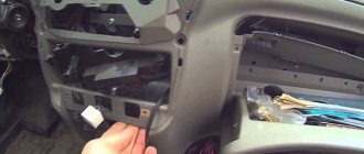
5. We get to the rubber gasket of the harness in the interior, remove it, then go into the interior, look under the mounting block and see “the light at the end of the tunnel.”
6-7. Having found our bearings, we bring the corrugation into the cabin, the length of the corrugation is also good, it’s enough to bring it into the cabin and then after 5-10 centimeters just wires with lyre terminals begin, which we will now insert into the mounting block in places F16-10A - PTF on the starboard side and F17-10A - PTF on the left side. As you can see, the length of the wires is enough directly to the end of the front door; through the line it is enough to reach the steering wheel.
8. We free the mounting block from the grip of the end screw (there can be a lot of swearing here) and move the block to the left, then we move the bottom towards the motor and place it with the bolts facing down. We inserted the incoming pluses of the lamps, now we take the double from the set and insert it side by side into the same fuses F-16 and F-17. From here we lead the double to the 87th relay contact.
9. The ground in the set is a little short, its length is enough if you just re-crimp the ground contact from some relay nearby, or connect to them using a connecting mounting block, which I don’t recommend using, it’s better to throw them away right away so as not to be tempted, but I didn’t bother potato there and made my own wire - on one end there is a mother terminal for the relay, and on the other there is a round terminal for a screw, and I hooked it to the mousse and led it to contact 86 of the relay. Contact 3 Musa and his block hold the lyre terminals, if there are none, then a terminal from the ISO audio connector will do. We crimp everything and heat shrink it. On the musa, contact 3 is connected to contact block number 5, and this is where we will insert the low-current control wire. From here we look at the length to the relay, take another wire so that the length is enough to reach the instrument cluster and crimp them into one with the mother terminal and insert it into the relay at pin 85, and hook the jumper that goes to the speedometer to the 15th leg to indicate PTF.
12. I decided to take out the additional relay, they all fit tightly and I even had to first remove three more relays in order to conveniently remove what I needed. We remove and look at the right leg into small squares (rectangles), insert an awl, needles or small drills and bend the ears of the terminal to pull it out of the seat. At the exit we take out such a healthy lyre terminal, it’s the first time I’ve seen one like this). Ideally, we take a new terminal of the same type and crimp our power red wire from the set with this blue one (a thin yellow-blue wire is also powered to it). We get a reliable and high-quality connection - even in this case you can do without twists, electrical tape and other snot. We insert another contact onto the 3rd pin of the relay.
13. That’s it - we secured the minus lamps, brought the pluses into the block, there, through the previous ones, our double went to the 87th leg of the relay, the mass from the 86th leg was hooked to the body, the power wire was fed after ignition to the 30th leg of the relay, and another double from the 85th leg The relay went to the 15th contact in the CP and to the 3rd in the mus (to the fifth to the block). We install the relay, we admire that they were placed among the standard ones) To the left of the PTF relay, I installed a trunk release relay on the same mounted block. We insert fuses, the kit included Avar companies, it is better to replace them in China, for one Dravovian grantmaker, the fuse from the kit did not burn out, but melted the body. We screw the speedometer and new mus into place.
14. We checked everything a hundred times, make sure that everything we have piled up is correct and go and breathe outside, screw the PTF ourselves. The length of the wires here is enough to easily remove the bumper, put it on the ground and then disconnect the wires from the PTF.
15. Put the fender liner and bumper in place, connect the ground to the battery, close the hood and admire the view). By the way, I made this lip out of vinyl film.
16. We return to the salon, turn on the ignition, it turned on and it’s good that we didn’t break anything, since the web from the braid to the mounting block is short and it’s not convenient to unfold it, everything is tight. We start the car to reassure ourselves that it will at least start, and to gain voltage from the genes in order to test our PTF, and the combination of the near one with the PTF and ZPTF and the far one on top). Everything is timid eee)) if only it wouldn’t work, we thought it all over, brainstormed it, carried it out, let it down, checked it several times, so press the PTF button with confidence))).
PS: Here's what's left of the set
Thank you for reading, my respect to you) thumbs up.
Notes:
In accordance with paragraph 19.5 of the Road Traffic Rules, “During daylight hours, low beam headlights or daytime running lights must be turned on on all moving vehicles for the purpose of identifying them.”
Daytime running lights do not blind drivers in the oncoming lane and significantly reduce energy consumption in the vehicle.
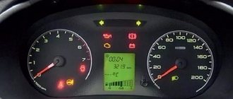
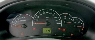
Daytime running lights on a Lada Granta light up when the ignition is turned on and continue to light when the car is moving.
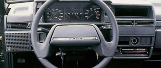
The block is located on the instrument panel, to the left of the steering column.
External lighting control unit and headlight beam direction controller:
1 – external lighting switch;
2 – key for turning on the fog light lamp in the left rear light;
3 – regulator of the direction of the headlight beams.
Outdoor Light Switch
The external lighting switch has 3 fixed positions (and in the optional version there are 4):
- The extreme left position of the switch handle (position “0”) – the external lighting is turned off.
- When the handle is moved to the middle position, the side lights, instrument panel lights and license plate lights are turned on. At the same time, the daytime running lights are lit.
- When you turn the handle to the right, in addition to the above-mentioned lamps, the low or high beam headlights are turned on, depending on the position of the left steering column switch (daytime running lights do not light up in this position of the handle).
- In an embodiment, the switch position at “4” indicates automatic turning on and off of the side headlights and low beam, depending on the state of external lighting.
Headlight beam direction control
The headlight beam direction regulator is designed to adjust the angle of the headlight beam in the vertical plane depending on the vehicle load. The correct angle of headlights reduces the risk of dazzling oncoming drivers. In a variant, the low beam corrector has the following positions: “0”, “1”, “2”. Combining the mark on the switch handle and the number on the unit body ensures headlight adjustment for the following vehicle loading options:
– there is a driver with a front passenger or the driver himself in the cabin;
1 – driver plus four passengers or driver plus cargo in the luggage compartment;
2 – driver plus four passengers with loaded luggage compartment.
Rear fog light switch
The fog lamp in the left rear lamp is turned on and off by pressing the key when the headlights are on. By pressing the switch the first time, the fog lights work; pressing the switch again cancels the fog lights.
And lastly, the front fog light switch, only in a variant version. To turn them on, press the switch key “4”, also with the side lights on. Pressing again turns off the front fog lights.
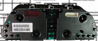
Lighting control module Lada Kalina.
Lighting control modules 344.3769, 345.3769 are designed for switching electrical control circuits for external lighting, front and rear fog lights, adjusting the level of illumination of controls and instruments, and controlling the angle of the light beam of automobile headlights.
Numbering and assignment of contacts.
Main characteristics.
Rated voltage, V: 12.
Rated load:
- Active: 2 mA pin G, 0.001-0.1 A pin 2 (load is switched to pin 31).
- Inductive, at 100 mH: 0.15 A pin 4.
- Tube: 35 W (3.3 A) pin 58b, 10 A pin 56 and pin 58.
Viewing surface color: black.
Character color: white.
Symbol backlight color: light green.
Indicator illumination color: rear fog lights - yellow, front fog lights - light green.
Properly installed PTFs help the driver control the car in difficult road conditions. Traffic rules strictly regulate the height of headlights, their color, as well as the position of light spots on the road.
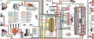
Grant's electrical circuit responsible for the engine compartment
Here are the main parts of the Lada Granta wiring, which are responsible for the normal operation of the power plant:
- 1 – power supply to the headlight, front right;
- 2 – power supply for windshield washers;
- 3 – voltage to the left side of the head optics;
- 5 – on-board power supply;
- 6 – head fuse block;
- 7 – generator;
- 8 – horn;
- 9-11 – terminal blocks to the dashboard;
- 12 – contact pair of rear headlights;
- 13 – main radiator fan drive.
Where can I install PTF
In the design of the modern Granta, the installation locations are precisely worked out: under the license plate, on the sides. Some bumpers even have recesses there . In any case, for proper installation, the front bumper of the car will have to be removed.
But before that, you should go shopping and find the necessary parts. Today's market offers both bumpers with recesses and bumpers with headlights already installed. The choice, as always, remains with the owner.
Most Lada Granta cars do not have fog lights, but there are recesses in the bumper for do-it-yourself installation
Lada Granta diagram - ignition part
- 1 – indicator of lubricant pressure in the crankcase of the power plant;
- 2 – generator connector;
- 3 – power supply to the fuel mixture supply valve;
- 4 – cooling system thermometer;
- 5 – sending a signal to the dashboard;
- 6 – adsorber purge;
- 7 – speedometer;
- 8 – mass air flow sensor;
- 9 – DPKV;
- 10 – DC in front of the catalyst;
- 11 – control pulse device;
- 12 – oxygen concentration sensor in exhaust gases;
- 13/14 – coil and spark plugs, respectively;
- 15 – injector drivers;
- 16 – ignition contact group;
- 17 – detonation measurement sensor.
Grant instrument pinout - dashboard diagram
This part is the most difficult. The large number of pins and the miniature size of the terminals greatly complicates the search for the required group:
- 1/2 – connecting blocks for the front electrical harness;
- 5 – lighting control unit;
- 6 – ignition switch module;
- 7 – on-board computer;
- 8 – lever for switching the position of the wipers;
- 9 – tidy;
- 10 – control of emergency modes;
- 11 – cargo compartment lid lock;
- 12 – diagnostic connector;
- 13 – block for the air intake drive;
- 14 – button to turn off the heated rear windshield;
- 15 – emergency contact;
- 16 – brake light switch;
- 17/18 – contact group – output to radio equipment (radio tape recorder);
- 19 – rotating equipment module;
- 20/41 – driver/passenger airbag drive;
- 21 – horn power supply;
- 22 – mounting block group;
- 24 – cigarette lighter group;
- 25 – backlight for stove control;
- 26 – interior lamp;
- 27 – contact group of the ignition switch;
- 28 – controller;
- 29 – incoming connector to the rear of the on-board network;
- 30 – electronic part of the gas pedal;
- 31 – additional resistor;
- 32 – stove motor;
- 33 – heater switch block;
- 34 – door lock module;
- 35/36 – cooling system head fan relay;
- 37 – compressor relay wiring;
- 38 – additional relay or reverse indication coil;
- 39 – air conditioner switch button;
- 40 – automatic transmission drive;
- 42 – evaporator thermometer;
- 43 – output to the rear wiring harness.
3/4 – similar for the feed harness;
Grant relay diagram
Relay location in the main mounting block located in the engine compartment:
- 1 – drive of the cooler of the cooling system;
- 2 – central locking protection;
- 3 – secondary starter relay;
- 4 – additional part of the relay;
- 5 – turn signal and emergency signal breaker relay;
- 6 – wiper drive protection;
- 7/9 – insertion of high/low headlight modes;
- 8 – horn protection element;
- 10 – heated aft windshield;
- 11 – main relay block;
- 12 – fuel pump relay.
Detailed diagram of the VAZ Grant (dashboard)
The vehicle is supplied to the market with a 32-pin instrument panel as standard. The standard pinout of the Grant shield has only 26 pins involved. Residual connectors are provided for the possibility of adding equipment or custom modifications:
- 1 – to the low oil pressure sensor in the engine crankcase;
- 2 – to the handbrake indication switch;
- 3 – intended for service needs when diagnosing the instrument panel;
- 4 – to external lighting switches;
- 5/6 – similar for right and left turn signals, respectively;
- 7/8 – CAN L/H;
- 9 – indication of seat belt position;
- 10 – contact of the Reset button of the steering column lever;
- 11 – response of the brake fluid reservoir sensor;
- 12/13 – on the head optics, high/low beam position;
- 14/15 – foglight terminals front/rear, respectively;
- 16/18 – receiving immobilizer antenna signal;
- 17 – ground wire of the instrument panel;
- 19/21 – to terminal No. 30/15;
- 20 – for the drive of the electric power steering unit;
- 22 – for door closing sensors;
- 23/24 – MK buttons for forward and reverse, respectively;
- 25 – for an environmental thermometer;
- 26 – gas tank float indication.
Prior light control module circuit diagram
Light control units
Light control module in Lada cars
Basic control elements for Lada car lighting devices and interior lighting.
The light control unit is an element that allows the driver to turn on and off the side lights, low or high beam, providing the necessary degree of visibility of the road situation. Additionally, the Lada lighting control module allows you to adjust the headlight angle.
Basic provisions VAZ light control unit
By default, the system has three fixed positions:
- left (all lights are turned off);
- average (only side lights work);
- right (high or low beam lights up depending on the position of the petals on the steering column).
Additionally, the light control module for Lada Priora, Granta and Kalina includes an instrument panel lighting control for more comfortable control. To reduce the degree of blinding of drivers of oncoming cars, there is a corrector switch on the right, which has four positions:
- 0 (only the driver’s seat or additionally the front passenger seat is occupied);
- 1 (all seats occupied);
- 1 (driver's seat occupied and trunk loaded);
- 1.5 (all seats in the cabin are occupied and the trunk is additionally loaded).
Additionally, the Lada MUS includes a key to turn the fog lights on and off (their activity is indicated by a burning yellow indicator). The fog lights turn on automatically when the high or low beam is on.
Conceptually, the Lada light control module is no different on all models of the Volga Automobile Plant. The differences between Kalina, Granta and Priora of recent years of production lie in the shape and dimensions of the block, the specific relative arrangement of control elements, and nuances in technical design. For example, turning the fog lights on and off can be done using separate keys.
Additionally, the driver can install an automatic light control module for the Lada. It allows you to automatically turn on the low or high beam when the ignition is turned on. This will ensure that you drive with running lights, as required by current traffic regulations. VAZ light control unit costs between 700-1500 Russian rubles (depending on the specific model) and can be installed independently (no special qualifications are required).
The car also has a control unit for interior light, which has the following three positions:
- the lights are turned off;
- the lighting automatically turns on when the doors are open and goes out after closing after some time;
- the light is always on.
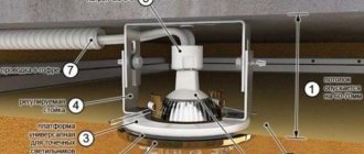
This control module is located under the ceiling next to the lamp.
Tags: Lada lighting control module, light control unit, Lada light control module, Lada MUS
From September 21 to 24, 2022, the 21st Motorexpo car exhibition was held in Togliatti. We couldn’t ignore this bright event in the automotive industry and visited the car show on the opening day.
We are publishing the first photos of the new Largus Van with an enlarged body, which AVTOVAZ presented at the Comtrans 2017 motor show.
Lighting control modules MUS 50.3769, 521.3769, 522.3769, 58.3769, 582.3769 are designed for switching electrical control circuits for external lighting, front and rear fog lights, adjusting the level of illumination of controls and instruments, and controlling the angle of the light beam of automobile headlights.
Lighting control module MUS 50.3769 for Lada Granta, VAZ-2190, Lada Kalina FL, VAZ-2192, VAZ-2194, characteristics, contact assignments.
The lighting control module MUS 50.3769 is connected to the electrical equipment system of Lada Granta and Lada Kalina FL using block 1118-3724500.
Main characteristics of the lighting control module MUS 50.3769 for Lada Granta, VAZ-2190, Lada Kalina FL, VAZ-2192, VAZ-2194.
Rated voltage, V: 12 Rated load: - Inductive: 110 mH; 0.5 A contact 56, 50 mH; 0.25 A contact 1 - Lamp: 10 A contact 58 and contact 3, 5 A contact 4, 2.5 A contact 2 Color of the viewing surface: black Color of symbols: white Color of symbol illumination: light green Dimensions, mm: 70x110x64 Weight, no more, kg: 0.2
Lada Granta: wiring diagram for rear wiring harness devices
The rear part of the car wiring is responsible for the equipment of the stern and sides of the car. all additional equipment is connected exclusively through this part of the highways:
- 1/2 – contact group for the dashboard;
- 3/4 – direction indicators;
- 5 – handbrake indicator;
- 6 – rear window heating contact;
- 7 – interior lamp;
- 8 – indicator of the driver’s seat belt position;
- 9 – cargo compartment illumination lamp;
- 10 – fuel pump drive;
- 11/15 – aft dimensions for the left and right sides;
- 12 – trunk lid lock drive;
- 13 – button for turning on the interior lamp;
- 14 – additional stop chain;
- 16-19 – door terminal blocks for the rear left, rear right, front left and front right doors;
- 20 – airbag control drive;
- 21 – contact group of license plate lights;
- 22 – on the dashboard;
- 23/24 – rear speed indicator sensors;
- 25/26 – seat belt pretensioners;
- 27 – group of dashboard contacts.
We add an indication of PTF operation to the instrument cluster of Lada Granta and Kalina 2
Owners who want to install fog lights (FTL) on the Lada Kalina 2 or Lada Granta are faced with the fact that there is no indication that the front fog lights are on on the instrument panel. Apparently AVTOVAZ decided that if the vehicle does not have front PTFs in this configuration, then an indication on the instrument cluster is not needed. Further instructions tell you how to install the PTF LED in the dashboard of Lada Granta and Lada Kalina 2.
You will need : disassemble the instrument cluster, prepare a soldering iron, 1 pc LED (type 3528) and 3 pcs resistors (type 101, 1.2 kOhm) (can be taken from the LED strip).
The dashboard board provides space for installing everything you need. Solder the resistors and LED to the places shown in the photo. Do not confuse the polarity of the LED, “Ground” of the LED is on the left, and “Plus” is on the right.
Before reassembling, check the installed LED. To do this, apply power to pin 15 of the dashboard block. According to the connection diagram, the same contact should receive “Plus”, which appears when the PTF is turned on.
By the way, when testing the instrument cluster, the LED installed independently will not light up.
Source
Preventive measures
In order for the factory wiring of the Lada Grant to serve for a long time and not break, experienced experts strongly recommend following a number of simple rules.
- Periodically check all contact connectors and terminals for oxidation and rust. Such damage to the connections can cause a short circuit and a critical decrease in the conductivity of the line, which is perceived by the on-board computer as an error or breakdown.
- Use only original consumables and electronic components. The use of counterfeit products does not guarantee the functionality of the circuit. At the same time, some elements, when damaged, cause a voltage drop in the network, which becomes a direct cause of failure of other equipment or a fire.
- Use special oil to treat contact groups. The fluid is sold in auto shops or electronics stores. After treatment, the contacts are covered with a moisture-impermeable layer, which increases their service life by 2-3 times.
- Carefully monitor the charge level and condition of the battery. The wiring of the Lada Granta critically perceives a significant voltage drop in the on-board circuits. As a result, this may cause damage to the firmware of electronic control units.
Main characteristics of the electrical equipment of the Lada Granta car
Before you begin to study the electrical circuit, you need a clear understanding of the systems and all equipment of the car. It consists of the following:
- All systems are powered by a 12 volt battery, therefore no other voltages are permitted.
- To protect electrical networks in the car, blocks with safety elements and relays are installed. Often a car malfunction occurs due to a blown fuse. For example, if you cannot start the car, then this must be a faulty relay or a breakdown of the safety element of the fuel pump part.
- The main component of a car's electronic system is the engine control unit. Of course, if there are malfunctions in this system, the car’s engine will not start.
- All the most important electronic devices are connected via a terminal block and cable bundle to the instrument panel. If any icon remains on the dashboard after turning on the ignition and starting the engine, then there is a malfunction in the system.
- The engine control system (ECM) includes: controller (ECU); sensors monitoring engine parameters; executive modules. The ECU is located below the glove compartment, under the passenger's feet, namely under the floor covering. Its function includes: supplying voltage to sensors and actuators; control system diagnostics; troubleshooting and storing error codes.
Frequently encountered problems in the stable operation of electrical equipment:
- relay failure, fuse breakdown;
- corrosive deposits on connector contacts;
- fuse links burn out;
- failure of contacts in the terminal block.
A diagnostic device and a geographical image of the electrical connections of equipment and car systems will help to detect all damage.
Having an electrical circuit in the glove compartment, the driver will be able to fix a small malfunction on his own, this is especially true on a long journey. A knowledgeable driver, having studied the diagram of the required unit, represents the functional purpose of a particular circuit. However, we must remember that the electrical circuit of the Lada Granta equipment is quite complex for a person who is not related to technology. Therefore, in this case, if a malfunction is detected, you must contact specialists. In conclusion, a small reminder: electrical wiring cannot withstand large voltage drops in the on-board network. In other words, it is necessary to monitor the condition and state of charge of the battery.
Diagnostics and repair
All electrical equipment of a Lada Granta car must be diagnosed using multimeters and test benches. If damage is detected, the element is replaced exclusively with a known good one. The use of used parts can lead to unexpected breakdowns and incorrect operation of equipment and devices.
The electrical circuit of the Lada Granta is a complex part of the car's equipment. Diagnostic work and repair of on-board circuits must be carried out with the required tools and necessary knowledge. In the absence of the above, it is recommended to contact qualified professionals for help.
Instructions for installing headlights for dummies
The entire process of equipping a car with foglights can be divided into several stages:
- Removing the bumper.
- Installation of headlights.
- Wiring.
- Connecting headlights.
- Reassemble the parts in reverse order.
Removing the front bumper
The Granta's bumper is integral with the radiator grille, so in order not to distort the latches under the wings, it is advisable to remove it together with a partner.
Photo gallery: necessary tools
- crosshead screwdriver;
- 10 mm wrench, 10 mm socket;
- 8 mm wrench;
- TORX T-20 wrench.