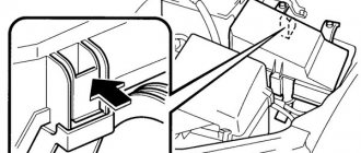
Here are the control diagrams for the VAZ-21120 and 21124 engines. They were installed on Lada hatchbacks of the 2112 family. A diagram of the on-board network is also provided. We are talking about engines containing 16 valves, and the electrical circuit on the VAZ-2112 consists of separate parts: engine control, general circuit. Power supply circuit for headlights, headlights, etc. discussed in the first chapter.
We study in the video how to enable self-diagnosis of the instrument panel to check its operation.
Equipment for VAZ 2112 passenger cars
| Automobile model | VAZ 2112 | VAZ 2112-01 | VAZ 2112-02 |
| Body type | All-metal, monocoque hatchback | ||
| engine's type | 16-valve with distributed fuel injection, V=1500 cm3 | ||
| Execution | "Standard" | "Norm" | "Lux" |
| Option code | 110, 115, 117, 122, 125, 130, 133, 134, 135, 137 GM (s.h.) 10 | 10, 13, 14, 19, 110, 115, 117, 122, 125, 130, 133, 134, 135, 136, 137 | 10, 11, 14, 16, 19, 110, 115, 117, 122, 125, 130, 133, 134, 136, 137 |
| Automobile model | VAZ 21122 | VAZ 21122-01 | VAZ 21122-02 |
| Body type | All-metal, monocoque hatchback | ||
| engine's type | 8-valve with distributed fuel injection, V=1500 cm3 | ||
| Execution | "Standard" | "Norm" | "Lux" |
| Option code | 10, 11, 13, 20, 21, 110, 115, 117, 119, 122, 124, 125, 130, 133, 134, 135, 136, 137 GM (c.c.) 11 | 10, 13, 19, 20, 30, 40, 110, 115, 117, 119, 122, 124, 125, 130, 133, 134, 135, 136, 137 | 10, 11, 16, 19, 20, 30, 40, 110, 115, 117, 119, 122, 124, 125, 130, 133, 134, 135, 137 |
Summary
So you got rid of the problem with the failure of the rear lights that tormented you for years. As you can see, it is still too early to write off the classic lamp and wires, since the electronic components are still far from ideal quality. And on the video attached to the article you will find useful information on the topic under consideration.
Products of the domestic automobile industry have always aroused a desire among car owners for independent servicing. There are several reasons for this: from high prices at service stations to the lack of professionalism of domestic service providers. Whereas many technical operations can be performed on a car yourself.
Wiring on a VAZ 2112: general diagram of connecting electrical equipment and devices
VAZ 2112 diagram
Front part of the diagram
| Position number on the diagram | Explanation of position |
| 1 | Flashlight |
| 2 | brake pad wear sensor (not installed on all cars.) VAZ 2112 |
| 3 | reverse light button |
| 4 | electric radiator fan motor cooling structure |
| 5 | signaling |
| 6 | gear motor for locking the right front door lock (on some cars a gear motor is mounted without the central locking switch turned on) |
| 7 | Relay for switching electric windows (Not installed on all cars.) |
| 8 | starter connection relay |
| 9 | starter |
| 10 | electricity storage |
| 11 | Magneto VAZ 2112 |
| 12 | electric windshield washer pump |
| 13 | low antifreeze level meter |
| 14 | gear motor for locking the left front door (on some cars a central locking switch is mounted) |
| 15 | left front door power window switch (Not installed on all passenger cars.) |
| 16 | low antifreeze level meter (Not mounted on all machines.) |
| 17 | windshield wiper gear motor |
| 18 | electric and pneumatic recirculation throttle (for a stove with air recirculation mode) |
| 19 | small heater damper gear motor |
| 20 | electric heater fan |
| 21 | button for the electric drive of the trunk door lock (not installed on all cars) |
| 22 | right front door power window switch (not mounted on all cars) |
| 23 | gear motor for power window of the right front door (not installed on all cars) |
| 24 | ECU central locking VAZ 2112 |
| 25 | additional resistor for electric heater motor |
| 26 | low brake fluid level meter |
| 27 | gear motor for power window of the left front door (not mounted on all cars) |
| 28 | light and headlight switch |
| 29 | instrument panel VAZ 2112 |
| 30 | rear fog light switch |
| 31 | indicator light for connecting rear fog lights |
| 32 | indicator light for connecting heated rear window |
| 33 | rear window heating connector |
Rear end
| Position number on the diagram | Explanation of position |
| 34 | steering column switches |
| 35 | instrument lighting regulator |
| 36 | ignition switch |
| 37 | block of relays and fuses VAZ 2112 |
| 38 | air recirculation connector (for a stove with air recirculation method) |
| 39 | stove ecu |
| 40 | hazard warning light switch |
| 41 | instrument lighting bulb |
| 42 | glove box light bulb |
| 43 | glove box light switch |
| 44 | cigarette lighter |
| 45 | on-board display unit for control structure of VAZ 2112 |
| 46 | ashtray light bulb |
| 47 | brake light switch |
| 48 | motor with gearbox for locking the left rear door (not mounted on all cars) |
| 49 | left rear door power window connector (not installed on all cars) |
| 50 | motor with gearbox for the electric window lifter of the left rear door (Not mounted on all cars) |
| 51 | carrying socket |
| 52 | alarm |
| 53 | motor with gearbox for power window of right rear door |
| 54 | right rear door power window switch (not installed on all cars) |
| 55 | motor with gearbox for locking the right rear door (not installed on all cars) |
| 56 | side turn signals |
| 57 | handbrake warning light switch |
| 58 | seat belt sensor (not mounted on all cars) |
| 59 | personal lighting lamp |
| 60 | interior lamp |
| 61 | cabin air heat meter |
| 62, 63 | interior light button |
| 64 | rear exterior lights |
| 65 | rear interior lights |
| 66 | room lighting fixtures |
| 67 | trunk light |
| A | terminal blocks for connecting the electric rear window washer pump |
| B | terminal block for connecting the engine control system wiring harness |
| IN | terminal blocks for switching wires when installing other types of headlights |
| G | contacts for connecting the trip computer |
| D, I | to the rear window defroster |
| E | contacts for connecting headlight cleaner (Installed on vehicle parts) |
| AND | terminal blocks for connection to the gasoline module (to the gasoline level indicator meter) |
| Z, L | to the motor with gearbox for the electric drive of the trunk lid lock (Installed on parts of the car) |
| TO | to the additional brake signal lamp |
| M | contacts for connecting the motor to the rear window wiper gearbox |
Complete diagram of VAZ 2112
Healthy ! Tightening torques for VAZ 2112
Installation of fog lights
Car owners can independently equip their car with fog lights. To make installation easier, you can watch videos from forums where craftsmen share their experience of such work.
Conclusions: in fact, replacing old wiring in the rear of a car is much easier than in the engine compartment or inside the cabin. And the diagrams proposed in the article will help you figure it out faster and avoid mistakes.
Wiring in a car plays one of the most significant roles, since it is actually the connecting link of many functional elements of the car. In the VAZ 2110, wiring is replaced if it malfunctions, or if the owner decides to upgrade. This, in turn, will help to significantly improve the efficiency of the vehicle's electronic systems. Often, old wiring simply cannot withstand the load of various additional high-tech devices. Replacing the wiring in a VAZ 2110 can be easily done on your own.
VAZ 2112 injector diagram
- injectors
- spark plugs
- ignition module
- diagnostic block
- ECU (since 2000 installed M1.5.4N or January 5.1) VAZ 2112
- cooling fan motor
- terminal block for connecting to the instrument panel wiring harness
- main relay
- main circuit fuse
- electric fan relay
- fan relay circuit fuse
- petrol pump relay
- petrol pump circuit fuse
- DMRV VAZ 2112
- dpdz
- dtozh
- CO potentiometer (not installed on machines with a modified control system; CO adjustment is made using the DST-2 device through the diagnostic block)
- empty control
- DD
- DPKV
- car speed sensor
- ECU anti-theft system VAZ 2112
- APS status indicator
- gasoline pump with gasoline level meter
- oil pressure sensor
- antifreeze heat indicator meter
- oil level meter
- DD (mounted on machines with a modified control system)
A - terminal block connected to the ABS cabin group);
B - contacts connected to the air conditioner wiring harness; C — terminal block to the fuse and relay block; D - to the plus of the electricity storage device; E - wires connected to the ignition switch (light bulb); F - terminal block connected to blue wires with a white stripe, disconnected from the ignition switch; G1, G2 — minus points; Together with the letter designation of the color of the wires on the injector diagram the VAZ 2112 passenger car , the designation of the number of the circuit element to which this wire is connected is used. For example “-7-“. In other cases, in addition to the designation of the element number, it is given through an oblique fraction and the terminal number, for example “-5/30”. The diagram does not show the connection points for the pink-black, red and green wires with a red stripe.
The car does not start - there is no charge in the battery
This problem occurs because the battery charge is going somewhere. It does not disappear by chance, but always for some reason.
Here are some of them:
- you leave the car outside at an ambient temperature of -20 degrees or below;
- the battery life is ending;
- The radio was left on in your car for some time, which led to a loss of charging power.
In all these cases, two types of treatment are usually used: firstly, urgently recharge, and secondly, buy a new battery. If you keep pulling and driving on a dead battery, soon you won't even be able to disarm your car. You will have to manually remove the terminals, trying to make it “silence”. The situation will immediately improve as soon as the battery is charged again.
Diagram VAZ 2112 injector 16 valves for Euro-2
1 — spark plugs; 2 — injectors; 3 — ignition module; 4 - ECU VAZ 2112; 5; main relay; 6 - fuse connected to the main relay; 7 — electric fan relay; 8 - fuse connected to the electric fan of the cooling structure; 9 — electric fuel pump relay; 10 - fuses, connected to the electric fuel pump relay; 11 — mass flow and air temperature sensor; 12 — TPS; 13 — DTOZH; 14 — electromagnetic throttle for purge of the adsorber; 15 — lambda probe; 16 - DD; 17 — DPKV; 18 — empty speed regulator; 19 — VAZ 2112 immobilizer computer; 20 — immobilizer status indicator; 21 — phase sensor; 22 — car speed meter; 23 — gasoline pump module with fuel level meter; 24 — oil pressure control sensor; 25 - coolant heat indicator meter; A - terminal connected to the ABS cabin group harness; B - diagnostic connector; B - terminal block connected to the air conditioner wiring harness; G - to the plus terminal of the battery; D - to the terminal block of the side door wiring harness; E - terminal block connected to the instrument panel wiring harness; G1, G2 - ground points; I - the order of conditional numbering of the terminals in the wiring block of the immobilizer computer; II - the order of conditional numbering of terminals in the diagnostic connector.
Scheme VAZ 2112 injector 16 valves for Euro-2 with controller M7.9.7
What's better
One of the questions that 2110 owners ask is which headlights are best to choose for this vehicle. For the VAZ 2110, only Bosch and Kirzhach headlights are standard. If we consider the secondary market, what headlights are suitable for a foreign car?
This car configuration uses the following types of products:
- in the form of a monoblock;
- using lenses;
- modular;
- black;
- chrome plated;
- tinted.
In order not to be confused about which base is in the VAZ headlights, you can refer to the manufacturer’s documentation. Cars have a standard H1 base. When choosing new blocks, you need to focus on this feature.
Diagram VAZ 2112 injector 16 valves for Euro-3
| 1 — spark plugs; 2 — injectors; 3 — ignition module; 4 — VAZ 2112 computer; 5 — main switch; 6 - fuse connected to the main relay; 7 — relay of the electric fan of the cooling system; 8 - fuse connected to the electric fan of the cooling structure; 9 — electric gasoline pump relay; 10 - fuse connected to the relay with an electric gasoline pump; 11 — air mass flow and heat meter; 12 — rough road meter; 13 — TPS; 14 — DTOZH; 15 — idle control; 16 — control lambda probe; 17 - diagnostic lambda probe; 18 — electromagnetic throttle for purge of the adsorber; 19 — DD VAZ 2112; 20 — DPKV; 21 — immobilizer computer; 22 — immobilizer status indicator; 23 - DPRV; 24 — car speed meter; 25 — electric gasoline pump module with gasoline level meters; 26 — oil pressure warning light sensor; 27 — antifreeze heat indicator meter; A - terminal block connected to the ABS cabin group; B — diagnostic block; B - connector connected to the air conditioner wiring harness; G- to the “+” terminal of the electricity storage device; D — to the side door wiring harness connector; E - connector attached to the instrument panel wiring harness; G1, G2 - minus points; I - method of numbering contacts in the ECU wire connector by the immobilizer; II - method of conditional numbering of contacts in the diagnostic connector |
Diagram VAZ 2112 injector 16 valves for Euro-3 with controller M7.9.7
Prevention
If you suspect a malfunction, you need to check the resistance of the high-voltage wires using a multimeter. The black wire must be installed in the left hole, in the middle - the red one. The multimeter should be in the blue 20 position, the probes should be connected to each other.
If the resistance is zero, then everything is in order. If the multimeter needle shows 1, it means that the resistance is higher than the limit, such a wire must be replaced. Moreover, keep in mind that different wires can produce different resistance due to the difference in length.
Since the engine compartment environment is aggressive, even if one of the high-voltage wires produces increased resistance, you need to change all the wires on the VAZ 2110, because if one fails, then the others will soon fail as well.
It’s not at all difficult to make the replacement yourself; you just need to be careful and attentive. And we remind you once again: before reaching into the wires, disconnect the battery!
Connection diagrams for VAZ 2112
Rear window wiper and washer connection diagram
- 1 - electric washer motor
- 2 — block of relays and fuses
- 3 - ignition switch
- 4 - rear window wiper and washer switch
- 5 — motor with rear window wiper gearbox
- K6 - additional relyushka
- A - to sources of electricity
- B - method of conventional numbering of connectors in the terminal block of a motor with a gearbox
For the rear window wiper of a VAZ 2112, in a continuous manner, with a load of the motor with a gearbox with a force of 1 Nm, a supply voltage of 13.5 V and an ambient temperature of (25±10) °C, the number of double strokes of the output shaft of the gearmotor must be from 20-30 min- 1, and the consumed current is no more than 3 A. In intermittent order under the same conditions, the number of double movements of the output shaft of the motor with gearbox must be from 15 to 18 min 1 and the current used is also no more than 3 A. In this case, the initial 3 - 4 Swings after connection must be performed in a continuous manner.
Electrical diagram for connecting electronic ignition
| 1 - source of electricity; 2 — ignition switch; 3 — ignition switch; 4 — spark plugs; 5 — ignition module; 6 - ECU; 7 - DPKV; 8 — toothed disk; A - matching device |
The ignition structure uses a spark distribution method called the “idle spark” method. The engine cylinders are combined into pairs 1-4 and 2-3 and spark formation occurs in 2 cylinders at once: in the pot in which the compression cycle ends (working spark), and in the cylinder where the exhaust cycle occurs (idle spark). With a constant direction of current in the windings of the ignition coils, the spark formation current for one spark plug always passes from the central electrode to the side electrode, and for the second - from the side to the central one.
Electrical diagram for connecting the inflatable cushion VAZ 2112
| 1 — connector connected to the airbag module; 2 - diode; 3 - fuse 8 A; 4 - terminal block connected to a connector disconnected from connector 5; 5 — instrument panel harness connector, connected to the ignition switch; 6 — signal connection switch; 7 - connector connected to the terminal block disconnected from block 8; 8 — instrument panel harness connector, connected to the fuse and relay block; 9 - connector connected to the terminal block disconnected from connector 10; 10 - instrument panel harness connector, attached to the front wiring harness |
Attention ! Removal and installation of a steering wheel with an airbag must be performed without the use of electric tools. Do not disassemble or repair the computer, airbag module and steering wheel contact coil. After turning off the battery, you must wait at least 5 minutes before disassembling.
Unbreakable connection
The machine and its electrical circuit cannot exist separately; this union is indestructible, like the foundations of the Chinese wall.
Almost all systems, in one way or another, depend on electricity and, in its absence, not only refuse to work correctly, but do not function at all.
Here are just a few of these interactions:
- ignition of the combustible mixture in the fuel system of both carburetor and injection type engines;
- supplying electricity to the starter when starting the engine;
- instrument panel illumination at night;
- informing other road users about the desire to carry out a maneuver using a light indicator “right” or “left”;
- playing a sound signal to prevent an accident;
- turning on the side lights to identify the vehicle at night.
Let's move on to the electrical circuit itself.
Among other things, the presence in the “Manual” of printed electrical diagrams with detailed descriptions makes it an indispensable assistant in not only accurately identifying symptoms, but also “prescribing treatment”, finding out the most important question of why it hurts, and not just where.
It is important to understand from our diagram what the following auxiliary equipment is connected to:
- sound signal;
- wipers;
- cassette player or radio;
- interior lighting;
- heated rear and front windows;
- power windows (if equipped).
The task is important for the reason that in a car there is a certain interdependence of some (main) systems from others (auxiliary). Some work in pairs, while others work in threes or even fours. If you know exactly this connection, you will immediately find your bearings. If there is no current supply to the glow plugs, then, most likely, other subsystems that work together are not functioning.
VAZ 2112 wiring diagram
Alternator wiring diagram for VAZ 2112
| Position number on the diagram | Explanation of the position on the diagram |
| 1 | current storage |
| 2 | generator VAZ 2112 brand 94.3701 alternating current, three-phase, with built-in rectifier unit and electronic voltage regulator, right rotation (drive side). |
| 3 | Relay and fuse block |
| 4 | ignition switch |
| 5 | battery charging warning light located on the instrument panel |
Some machines were equipped with AAK-5102 generators made in Slovenia. In terms of its characteristics and connection dimensions, it is identical to the generator 94.3701.
Starter wiring diagram
- accumulator battery
- magneto
- starter VAZ 2112 model 57.3708
- ignition switch
Wiring diagram for headlights and fog lights VAZ 2112
The low and high beam headlights are connected using the K4 and K5 relays located in the relay and fuse box.
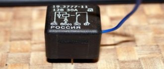
Wiring diagram for fog lights VAZ 2112
On the VAZ 2112 hatchback, in a variant modification, fog lamps are mounted in the front bumpers. The diagram of which is presented below.
| 1 — fog lamps; 2 — relay for connecting fog lamps brand 113.3747; 3 — connecting block of VAZ 2112 relays and fuses; 4 — size switch; 5 — fog light connector; A - to the source of electricity; B - to the instrument light switch |
Electrical wiring diagram for outdoor lighting
Wiring diagram for hatchback turn signals and hazard lights
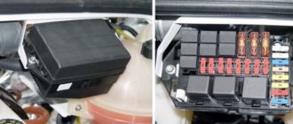
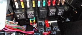
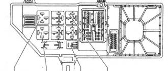
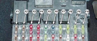
VAZ2112 fuses and relays
- F1 5 License plate lamps. Instrument lighting lamps. Side light indicator lamp. Trunk light. Left side marker lamps
- F2 7.5 Left headlight (low beam)
- F3 10 Left headlight (high beam)
- F4 10 Right fog lamp
- F5 30 Electric door window motors
- F6 15 Portable lamp
- F7 20 Electric motor of the engine cooling system fan. Sound signal
- F8 20 Rear window heating element. Relay (contacts) for turning on the heated rear window
- F9 20 Recirculation valve. Windshield and headlight cleaners and washers. Relay (coil) for turning on the rear window heating
- F10 20 Reserve
- F11 5 Right side marker lamps
- F12 7.5 Right headlight (low beam)
- F13 10 Right headlight (high beam). High beam warning lamp
- F14 10 Left fog lamp
- F15 20 Electric seat heating. Trunk lock lock
- F16 10 Relay-breaker for direction indicators and hazard warning lights (in emergency mode). Hazard warning lamp
- F17 7.5 Interior lighting lamp. Individual backlight lamp. Ignition switch illumination lamp. Brake light bulbs. Clock (or trip computer)
- F18 25 Glove box lighting lamp. Heater controller. Cigarette lighter
- F19 10 Door locking. Relay for monitoring the health of brake light lamps and side lights. Direction indicators with warning lamps. Reversing lamps. Generator excitation winding. On-board control system display unit. Instrument cluster. Clock (or trip computer)
- F20 7.5 Rear fog lamps VAZ-2112.
- K1 – lamp health monitoring relay;
- K2 – windshield wiper relay;
- K3 – relay-interrupter for direction indicators and hazard warning lights;
- K4 – headlight low beam relay;
- K5 – headlight high beam relay;
- K6 – additional relay;
- K7 – relay for turning on the heated rear window;
- K8 – backup car relay.
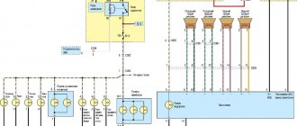
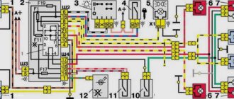
Electrical control circuit for the VAZ 2112 engine
| Position number on the diagram | Explanation of the position on the diagram |
| 1 | sprayers |
| 2 | spark plugs |
| 3 | ignition module VAZ 2112 |
| 4 | diagnostic connector |
| 5 | electronic engine control unit VAZ 2112 |
| 6 | terminal block connected to the instrument panel wiring harness |
| 7 | main relyushka |
| 8 | fuse combined with the main relay |
| 9 | electric fan relay |
| 10 | fuse located with the electric fan relay |
| 11 | electric fuel pump relay |
| 12 | fuse located with the fuel pump relay |
| 13 | Mass air flow sensor |
| 14 | TPDZ |
| 15 | DTOZH |
| 16 | idle speed regulator |
| 17 | oxygen sensor |
| 18 | DD |
| 19 | DPKV |
| 20 | electromagnetic throttle for adsorber purge |
| 21 | DPRV |
| 22 | APS control unit |
| 23 | APS status indicator |
| 24 | car speed meter |
| 25 | gasoline pump with fuel level sensor |
| 26 | oil pressure warning light sensor |
| 27 | Coolant heat indicator sensor |
| 28 | oil level meter |
| A | terminal block connected to the ABS cabin group harness |
| IN | connector that connects to the air conditioner wiring harness |
| WITH | connector that connects to the electric fan wiring harness |
| D | wires connected to the ignition switch (light bulb) |
| E | terminal block connected to the blue-white wires disconnected from the ignition switch |
| F | to the plus terminal of the current accumulator |
| G1, G2 | mass points |
Along with the letter designation of the wire colors in this diagram, the designation of the number of the circuit element to which this wire is connected is used. For example -4-. The symbol -S7- or -SF- means that the core is connected to the circuit element numbered 7 or indicated by the letter F through a connection point not shown in the diagram. In some cases, in addition to the designation, the element number is given through an oblique fraction and the connector number, for example -5/15-.
How to upgrade them
- The good news is that we will no longer need conductive tape - neither new nor old. In any case, AvtoVAZ itself abandoned this “karmically” unsuccessful detail in the design of the rear lights of the VAZ 2114 or VAZ 2115 models.
- The bad news is that your car with such tape in the headlamp unit may present an unexpected and unpleasant surprise at the most inopportune time.
But there is a way out - to modernize it yourself, and in fact simplify the design of the rear lights.
Penny purchases
- costs less than the original. And the proposed method will allow you to keep it within 250 rubles;
- simplifies the design. That’s how it will be, because it’s not for nothing that this method is used everywhere.
- a set of single sockets for direction indicators;
- double sockets for brake lights and parking lights;
- male-female copper connectors;
- high-quality wire 2-3 meters.
Independent steps
Having removed the rear lights from the car, we begin to modernize them. To do this, you will need instructions that will show you how to remove the lighting fixture.
Don't forget that modern cars are full of plastic parts that can easily be broken due to carelessness. When dismantling, try to do everything carefully
Note! You will need a wiring diagram for the VAZ 2112 injector, and the good news is that it is posted at the beginning of the article.
Locksmith stage
- in the plastic panel of the headlight housing we mark places for cartridges;
- then we cut holes for them;
- We fix them with self-tapping screws.
Electric stage
- We cut off a piece of wire and use it to make a common “ground”. To do this, we connect the “-” terminal of all cartridges in series, having previously secured the male-female connector to the wire;
- Cut the wire again and connect it to the “+” turn terminal;
- Using the next piece of wire we connect the “+” terminal of the side and stop lights in series;
- Referring to the diagram, we connect the connector block with the free ends of the wiring.
Tip: be sure to test the assembled circuit to identify a short circuit.
Books and diagrams for repairing VAZ 2112
Here you can download the following books and diagrams for the repair and operation of VAZ 2112 .
| Order number | Name of manual or catalog | The year of publishing | Col. p. | Size | Format |
| 1 | Catalog of parts VAZ 2112, 2111, 2110 | — | 406 | 7.57 MB | |
| 2 | Operating manual for VAZ 2112, 2111, 2110 | 2008 | 92 | 1.56 MB | |
| 3 | Repair of VAZ 2101, 21011, 2103, 2105, 2106, 21073, 2121, 21213, 21214, 21214-10, 2123, 2130, 2108, 21081, 21083, 2110, 2111, 2112 engines | 2002 | 83 | 2.65 MB |
Why are taillights bad?
The real fly in the ointment for the VAZ 2112 model was the work of the rear lights.
- the conductive tape in the flashlight body has poor contact;
- unstable contact and increased frequency of operation leads to lamp burnout;
- Despite the fact that their price is low, replacement will only help for a short time.
Warning! Unfortunately, replacing the conductive tape from the same manufacturer will also not solve the problem.
Conductive tape - a cheap part with a short life term
Cylinder block and connecting rod-piston group (SHPG)
This is the main part of the engine in which the energy of burned fuel is converted into mechanical energy. It consists of a cylinder block, pistons, connecting rods, connecting pins of support bearings, a crankshaft and half rings that limit the displacement of the latter relative to its axis.
The VAZ 21124 engine with 16 valves is equipped with a “high” block 11193, which received its nickname due to its size. It is cast from cast iron, and then it is machined to accommodate the cylinders. Its height is 197 millimeters (from the axis of rotation of the crankshaft to the top edge). It is 2.2 mm higher than the cylinder block used in the 21120 engine. This increase allowed the displacement to be increased to 1.6 liters without increasing the cylinder diameter. The block is also distinguished by a reduced size of the holes for the cylinder head mounting bolts.
The crankshaft (catalog number - 11183 -1005016), like the block, is cast from cast iron. The journals (points of contact with other parts) are polished and holes are drilled in them to lubricate the support and connecting rod bearings. To reduce vibration from rotation, 8 counterweights are installed on the shaft, shaped like half a disk.
The connecting rods are forged from steel and consist of two heads - upper and lower. At the top there is a bushing made of steel-bronze alloy for attaching the piston. Liners (sliding bearings) are pressed into the lower one. The connecting rod is attached to the crankshaft using a cover and 2 bolts.
Cylinder head (cylinder head)
It is cast from aluminum and performs the functions of injecting fuel into the cylinders and removing combustion products. Inside there are channels for pumping oil and coolant, which enter through several holes at the junction with the cylinder block.
The casting is completed with the following parts: valves, their guides and springs, hydraulic compensators, 2 camshafts (inlet and outlet) and their bearings. At the ends of the shafts on one side there are gears with a diameter 2 times larger than the crankshaft. On the other is a phase sensor operating on the Hall effect.
The main innovation in the cylinder head 21124 compared to eight-valve engines (2111 and 21083) is the automatic adjustment of the gaps between the valves and the camshaft cams. This was achieved by adding hydraulic compensators to the cylinder head design.
Supply system
This component is designed to prepare an air-fuel emulsion and deliver it to the cylinder inlets. It consists of 3 parts: air supply system, gasoline and receiver.
The fuel system includes a fuel rail with injectors, an electric pump, a tank and connecting pipes. The air supply system consists of a paper air filter, hoses and a throttle assembly.
The fuel supply works as follows. Based on a signal from the engine control unit, the pump is turned on and fuel enters the ramp. From it, fuel is injected through nozzles into the receiver, where it is mixed with air. The resulting mixture is drawn into it using the vacuum in the cylinder.
Information that a motorist must know before replacing existing wiring
Replacing wiring VAZ 2110
First of all, the car owner must know when and in what cases the car wiring is replaced. At the same time, it is also necessary to have information about the final operational life in order to objectively understand when the wiring may need to be replaced. List of the most common reasons that cause wiring to malfunction:
- the appearance of cracks in insulation during a long period of operation;
- oxidation;
- corrosion;
- fuse blown, etc.
Components needed to perform wiring replacement:
- multivariate set of wires;
- fuse block for VAZ 21104;
- housing for the heating system;
- various types of sensors: brake fluid, cooling system, etc.;
- pads;
- many terminals;
- Of course, it goes without saying, duct tape.
A practical look at rewiring
Replacing wiring on a VAZ 2110
So, a detailed step-by-step algorithm for replacing the wiring:
- first you need to dismantle the front part of the cabin;
- then you can deal with the proper degree of isolation, if there is a desire for it;
- after which, you need to pay special attention to the front headlight switch;
- The windshield wiper (see Replacing windshield wipers on a VAZ 2110 on your own) operates using its own mini-motor, the wiring of which must be checked for serviceability, since very often it simply becomes acidified;
- understand all heating modes;
- the connection of all electronic devices must be carried out strictly sequentially, by increasing the number of connected wires.
Note. Before disconnecting all electronic devices, it is necessary to draw your own conventional electrical circuit by hand in order to correctly make the appropriate connections in the future.
- now it’s time to tackle the fuse blocks, or rather their installation;
- most wires exceed the required length, so they simply do not fit into the allotted space;
- the bracket is the most rational solution to the problem; it will allow you to successfully replace the fuses with new ones;
- with the installation of a new fuse, the position of the front light indicator light, as well as the emergency warning light, will change;
- the heater will also have to be affected: first you need to remove the old radiator and then disassemble it to make it possible to replace the fan;
- Assembly is carried out strictly in reverse order.
Note. Before you begin the wiring replacement procedure, you need to find its current diagram. Otherwise, during the process of assembly and disassembly, you can quickly get confused, and you will have to send the car to a car service center.
Electrical diagram for VAZ 2110
The main advantages of the new wiring:
- the emergence of a practical opportunity to connect any gadget;
- longer service life compared to old wiring;
- high degree of reliability of everyday functioning;
- improving the quality and stability of electronic devices and much more.
Replacement of electrical wiring of VAZ 2110
It is always necessary to remember that installing homemade wiring is an easily feasible technical manipulation; the main thing is to understand all the necessary nuances.
Basic principles
Regardless of whether your VAZ 2110 has a carburetor or an injector, the basic principles for laying the wiring are the same. Finding a wiring diagram is not at all difficult, the main thing is to understand it. Actually, according to the location, the wiring is under the hood and in the cabin.
Its basic principles are the same, and boil down to the following:
- Whatever electrical device you have in a car, its connection will be single-wire. Moreover, the creators of the VAZ 2110 from the very beginning provided that both in the diagrams in the instruction manual and in reality, the colors of the wires would be clearly distributed. Simply put, all electrical equipment is connected using wires of a clearly defined color. Each unit has its own wiring harness enclosed in blocks. Naturally, this was done so that it would be easier for those who do the repairs themselves to understand this intricacy. Thus, replacing the wiring under the hood becomes more understandable. Advice: if you have a small problem with specific equipment and only one wire needs to be replaced, it is better not to be greedy and not change it to the first one you come across. Buy a complete harness and replace it with the wire of the desired color - it will be easier for you later;
- but the role of the “minus” (in other words, mass) is assigned to the automobile body;
- all terminals of any electrical consumers are directly connected to the body;
- Each system that is electrically connected has its own wiring harness.
the wire supplying power to the positive terminal of the battery is always braided in red; it is also advisable not to change its color. In all diagrams it is designated as “P”, that is, plus;
In the VAZ 2110, if the battery is connected, all electrical equipment is energized. That is why, in fact, before starting any repair (especially if it is related to the electrical part of the car), it is strongly recommended to disconnect the battery.
Video editing tips
Replacing worn parts with new ones, determining the location and cause of impacts, leveling something and installing it in place will work even without special skills and special tools. It will be enough to want to figure everything out, call a friend in the garage, watch a video or read this article. This wouldn't be possible if you had a foreign car full of electronics. And if you are also the happy owner of a VAZ-2112, then you have come to the right place.