Causes of malfunction
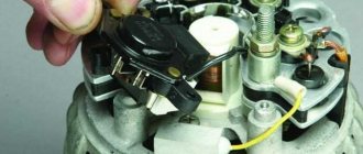
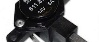
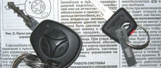
View of the old and new voltage regulator relay
There are several reasons for the failure of the regulator relay on a car. Let's consider the main ones :
- A short circuit in the on-board network, which led to the failure of the regulator relay. This happens quite often because the generator itself serves as the power source and there is no fuse between it and the current produced to protect it.
- Wear . Like any part in a car, the regulator relay can wear out.
- The brushes are worn out .
The arrow indicates worn brushes. Their length is 3 mm instead of the required 5 mm.
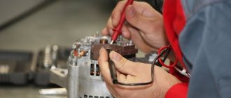
How to determine that the regulator relay has failed?
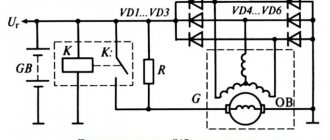
Connection diagram of the generator to the electrical circuit
Let's consider the main options:
- Insufficient battery charge means that after the ignition is turned off, the car has difficulty starting or may not start at all.
- The light shines normally at 2000 rpm, but dims at idle.
Once the root causes have been sorted out, you can move on to the replacement process.
Kalina generator design
The process of replacing the generator regulator relay
So, the process of replacing the generator regulator relay will require dismantling the product itself, but it will not require a pit, and all operations can be carried out from the engine compartment. Let's take a step-by-step look at how to replace the generator regulator relay on a Lada Kalina:
- We remove the “minus terminal”.
- To replace the relay, you will have to dismantle the generator.
The device serves to transform mechanical energy from the crankshaft into electricity. The generator charges the battery and is also a source of alternating current and power for all electrical equipment of the car. It has a diode bridge (rectifiers) and a voltage regulation unit, operating in parallel with the battery.
Fuse box in the passenger compartment
To access the mounting block, pull the bottom left corner of the cover to release the left locking point 1, then release the middle bottom point 2 and the two right locking points 3 and 6, then release the top locking points 4, 5 and remove the cover.
Installation of the cover is carried out in the following order: first snap the right fastening elements of the cover at points 6 and 3, then snap the lower fastening elements of the cover at points 2 and 1, then the upper ones at points 4 and 5. Make sure that the cover fastening elements fit exactly into the metal latches installed on the instrument panel.
| Mounting block 1118-3722010-00 |
| DELRHI mounting block |
| № | A | Protected Circuits |
| F1 | 15 | Ignition coils Injectors Engine control system controller |
| F2 | 25 | Norma, Lux: Central body electronics unit Driver door module |
| F2 | 5 | Standard: Daytime running lights |
| F2 | 303) | Window lifters |
| F3 | 15 | Norma, Lux: Automatic gearbox control controller Automatic gearbox control drive |
| F3 | 10 | Standard: Hazard Alarm |
| F4 | 15 | Airbag system controller |
| F5 | 7.5 | Terminal 15 devices |
| F6 | 7.5 | Reversing light Turn indicators (Standard) Automatic transmission control controller (Normal, Luxury) Parking control system control unit (Normal, Luxury) |
| F7 | 7.5 | Canister purge valve Mass air flow sensor/pressure sensor Phase sensor Oxygen concentration sensors |
| F8 | 25 | Rear window heater Heated exterior mirrors (Normal, Lux) |
| F9 | 5 | Side lights on the starboard side |
| F10 | 5 | Side lights on the left side Illumination of instruments and keys License plate lights Luggage compartment light Glove box light |
| F11 | 5 | Rear fog lights |
| F12 | 7.53) 10 | Low beam, right headlight Electrical corrector for right headlight |
| F13 | 7.53) 10 | Low beam, left headlight Electrical corrector of the left headlight |
| F14 | 10 | High beam, right headlight |
| F15 | 10 | High beam, left headlight |
| F16 | 10 | Right fog lamp |
| F17 | 10 | Left fog lamp |
| F18 | 20 | Front seat heaters Cigarette lighter |
| F181) | 10 15 | Cigarette lighter |
| F18 | 153) | Front seat heaters |
| F19 | 5 | Norma, Lux: Anti-lock brake control unit |
| F19 | 20 | Standard: Door locking motors |
| F19 | 153) | ABS |
| F20 | 15 | Sound signal |
| F20 | 153) | Horn Trunk lock Gearbox Cigarette lighter Diagnostic connector |
| F21 | 10 153) | Fuel pump |
| F22 | 25 | Windshield washer Central body electronics unit Rear window washer Rear window wiper |
| F22 | 153) | central locking |
| F23 | 5 | Instrument cluster Diagnostic connector |
| F23 | 103) | Daytime Running Lights |
| F24 | 7.5 | Norma, Lux: Air conditioning compressor clutch Automatic climate control system controller |
| F25 | 7.5 | Brake lights Interior lighting (Standard) |
| F26 | 10 | Norma, Lux: Central body electronics unit |
| F26 | 25 | ABS/ESC |
| F272) F31 | 25 | Anti-lock brake control unit |
| F282) F32 | 30 | Electric heater fan Automatic climate control system controller Electric power steering3) |
| Relay | ||
| K1 | Radiator cooling fan relay | |
| K2 | Window lifter (standard version) Minimum cooling relay for cooling module (luxury version) | |
| K3 | Starter relay | |
| K4 | Ignition switch unloading relay | |
| K5 | Turn signal and hazard warning relay | |
| K6 | Windshield wiper relay (standard version) Seat heating relay (luxury version) | |
| K7 | High beam relay | |
| K8 | Horn relay | |
| K9 | Low beam relay | |
| K10 | Heated rear window relay | |
| K11 | ECM relay | |
| K12 | Fuel pump relay | |
| K13 | Additional alarm relay | |
| K14 | Additional alarm relay | |
| K15 | — | |
| K16 | — | |
| K17 | — | |
Standard generator Grants
At the factory, VAZ 2190 and 2191 are equipped with a device with the catalog designation KZATE 115A (9402.3701-14). It has the following technical characteristics:
- rated voltage – 14 V;
- maximum current – 115 A;
- shaft rotation speed – 1200 rpm. (without load);
- shaft rotation speed at a maximum current of 115 A – 6000 rpm.
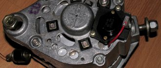
The main components of the generator are a stationary stator and a rotor rotating in it. The parts are separated from each other by an air gap. Their main working part is the winding and magnetic circuit. Other components serve to provide adequate rigidity, cooling, etc.
The brush assembly is necessary to connect the rotor electrical network to the stationary stator winding; it consists of several graphite contacts. A diode bridge is used to convert AC to DC current and is also called a rectifier block. The regulator converts the output electricity into the desired voltage.
Block under the hood
It is located next to the battery.
Photo - diagram
Description
Option 1
- 30A Low beam headlights or main relay, circuits protected by fuses F1 and F21 of the mounting block in the passenger compartment 50A Windshield heater
- 60A Generator
- 60A Generator
- 30/40A Heater fan (heater fuse grants)
- 50A Electromechanical power steering
- 60A ABS block
Option 2
- 60A Generator
- 60A Generator
- 30/40A Electric radiator cooling fan
- 40A ABS/ESP
- 25A ABS/ESP
- 50A Electric Power Steering Controller
Basic faults
Failures associated with the failure of the Granta generator lead to discharge or, conversely, overcharging of the battery and its boiling. In both cases, this will make further operation of the car impossible. If the belt is overtightened, problems with high bearing wear will soon arise. If the belt tension is insufficient, slipping will occur and the battery will receive too little charge.
Normally, a working generator produces 14.5 V; exceeding this value is most often due to a breakdown of the voltage regulator. Without urgent replacement of the element, constant recharging of the battery will lead to shedding of lead plates and battery malfunction. If the unit does not produce the required voltage, and it is below 13 V, then the problem may not only be with the regulator, but also with the fact that the brushes are worn out, the diode bridge or windings are damaged.
It happens that suspicious sounds occur during operation, in which case the nature of the noise is important. It’s not difficult to deal with this: just remove the wires from the generator. If the rotation of the pulley is accompanied by a howling or squealing noise, then the problem is in the bearings. If, after removing the wires, the noise disappears, then it is in the diode bridge, or a short circuit has occurred in the winding. In any case, repairs are inevitable, and sometimes only replacing the unit will help.
Typical faults and methods for their elimination:
Cause of malfunction
Remedy
The table shows the main faults. Mechanical and other damage is also possible.
Useful tips
Always try to keep your battery and alternator clean. Since contacts often oxidize due to moisture. And this greatly interferes with the normal operation of all electrical equipment. Often, deviations in the charging current occur precisely from dirt. Once you thoroughly clean the contacts and terminals, the fault disappears on its own, without any replacements or repairs. Cleanliness is the key to good health not only for a person, but also for a car.
Good day, dear friends!
I had a “crazy idea,” since this is not my line of work, to check the generator voltage regulator. Considering that I’m doing this for the first time, I’ll pose the questions at the end of the post….
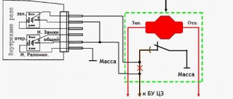
And so, in the generator of my car there is a voltage regulator from BOSCH 1197311557 (there are many substitutes, including TRANSPO IB545). I found a diagram showing how the regulator is involved in the electrical system. car equipment:
Using the “poke method”, I found a method (how to connect it) to test it in a garage. Only with this connection, I managed to get the lamp to work (glow):
I prepared everything I needed from what I found in the garage. — Soldering iron with soldering accessories. — Wires. — Light bulb. — Alligator clips. — Charger (with adjustable power supply function). I took it from friends. — Voltage regulator. — Multimeter. — Thin wires for the brushes, since it seemed that the crocodiles were squeezing the graphite brushes very tightly. In general, the following set turned out:
We look in TIS, we read, constant voltage regulator ... - 14.3 volts:
Based on this, I assume that if the voltage turns off (the lamp does not light) after 14.3 volts, then the voltage regulator is ideal. And so, as they say, “closer to the body.” We connect everything according to the diagram:
Turn on the charger and set the voltage to 12 volts:
Gradually add voltage. In the process:
After exceeding the voltage of 14.3 volts, the lamp no longer lit:
We increase the voltage further, the lamp does not light:
I raised the voltage to 17 volts (probably got excited), the lamp does not light:
When the voltage was reduced (in the reverse order), the light bulb lit up when it reached 14.3 volts (plus or minus 0.01 volts. It’s difficult to “catch” such a moment with this “equipment.”).
Everything seems to be fine, we can say that the regulator is ideal. But, … . And now the questions: — When the voltage reaches 14.28 volts, and before the lamp turns off at 14.3 volts, the lamp glows dimly and “flickers.” Is this normal, or is there a problem somewhere (in the regulator itself, or is the lamp selected incorrectly - its power (12 V, 10 W)? - The lamp glows dimly (at a voltage of 12.0 volts). What is the reason? - Maybe something Did you overdo it with the connection?
Something like this. Maybe someone (a professional in checking regulator relays) will correct my actions. I would be grateful and take your recommendations into account (for the future).
When the voltage relay breaks down, problems arise in the operation of electrical equipment. There can be many reasons for a failure in the voltage regulator, but the most common of them is boiling off of the electrolyte in the battery. The voltage regulator (VR) cannot be repaired; it is simply replaced with a new one. However, before you change it, you need to make sure that it is the one that is faulty. You can check the generator relay regulator yourself.
Alternative belt replacement options
Insufficient tension creates less inconvenience than constriction. The latter provokes too rapid wear of the bearings. To avoid such a problem, many Grant owners install the tensioner themselves: a part from the Lada Kalina is perfect for this.
The manufacturer does not initially install the part at the factory, since it positions Granta as the most affordable in its class, hence the savings on components. This is typical for the cheapest models with an 8-valve power unit.
To adjust the belt tension, you can use a bracket from Kalina, modifying it a little with your own hands. To do this you will need the following set:
- bracket;
- tensioner;
- roller bracket;
- alternator belt from Kalina 1;
- screw tensioner.
Thanks to this kit, you can significantly improve the design of your car, extending the service life of some parts and components.
Generator replacement
The problem with the standard Lada Granta generator is known to many owners of this car. To troubleshoot problems, it is most often necessary to remove the device. Conventionally, unit breakdowns can be divided into two types - mechanical and electrical. But one of the most common problems associated with replacing a device is the natural wear and tear of components. Therefore, sooner or later, every car enthusiast faces the question of replacing or repairing a generator.
The procedure has some difficulties, but it is quite possible to do it yourself. Removing the unit may also be necessary for maintenance or to improve the design of the car. The dismantling procedure has its own characteristics depending on the engine configuration (8- or 16-valve), as well as on the presence of air conditioning.
Replacing a generator on an 8-valve Granta engine
To work, you need to use three keys (at “8”, “10”, “13”) and a mounting blade. First, disconnect the “–” terminal from the battery. The operating procedure is as follows:
- Remove the engine protection by removing two rear and four front bolts.
- Disconnect the wire block.
- Remove the protective cap from the nut that holds the power wire.
- Unscrew the power cable nut.
- Release the top fastening by unscrewing the nut.
- Move the generator away with a mounting spatula or a long screwdriver, and remove the upper mounting bolt.
- Loosen the lower fastening.
- Press the generator from the engine using improvised means, for example, a mounting spatula, removing the lower mounting bolt.
- Move the generator to the right side.
- Remove the belt from the pulleys.
- Remove the generator.
To install the device in its original place, perform all steps in reverse order. You need to make sure that the grooves on the pulleys match the grooves on the belt.
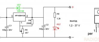
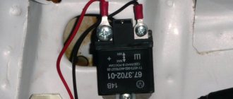
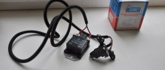
Review and installation of a three-level voltage regulator on LADA
One of the popular modifications among LADA car owners is the installation of a remote three-level voltage regulator (TRV). We'll tell you about its purpose and how to install it yourself.
What is it needed for
The load on the vehicle's on-board network varies widely. This depends on various factors, for example, the time of year (temperature) and sources of consumption. Low voltage causes the battery to be undercharged, which shortens its life. A remote three-level voltage regulator allows you to switch the battery charging voltage level as desired (for example, minimum 13.6V; maximum 14.7V).
Which TRN is suitable for LADA
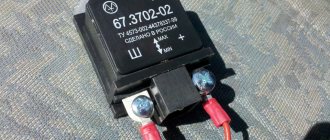
| Generator, article number | Automobile | TRG, article number |
| 26.3701, 37.3701, 371.3701, 372.3701 | VAZ-2107, -2108, -2109, -2110, OKA | 67.3702-01 |
| 3002.3771, 332.3771, 3202.3771, 3212.3771, 4302.3771, 94.3701, 9402.3701, 9422.3701, 3740.3771-38, 3743.3771-61, 3747.3771- 93, eld-a-21214, LG01214 | VAZ, GAZ | 67.3702-02 |
| 4052.3701, 409.3701, PRAMO “ISKRA” 5102.3771, -10, 5112.3771, -10, 5122.3771, -10, -30, 5142.3771, AAK 5727 | VAZ, GAZ, UAZ with generators PRAMO “ISKRA” 5102.3771, 5122.3771 | 67.3702-04 |
| G222 | VAZ-2104, -2105, -2107 | 67.3702-09 |
| 26.3701, 37.3701, 371.3701, 372.3701 | VAZ-2107, -2108, -2109, -2110, OKA | 67.3702-11 |
| 3002.3771, 332.3771, 3202.3771, 3212.3771, 4302.3771, 94.3701, 9402.3701, 9422.3701, 3740.3771-38, 3743.3771-61, 3747.3771- 93, eld-a-21214, LG01214 | VAZ, GAZ | 67.3702-12 |
| generators with an additional three diodes, the excitation winding of which is connected to the positive circuit | 673.3702 |
Where can I buy
: in our online store (Relays category).
Installation and connection instructions
For Lada cars (except Vesta, XRAY)
, photo author:
1.
Remove the generator.
2.
Remove the plastic casing of the generator. To do this, first disconnect the generator excitation wire. Then unscrew the nut from the stud (10mm wrench) and move the power wire to the side. Next, 3 latches on the plastic casing are unfastened.
3.
Remove the standard voltage regulator from the generator. To do this, unscrew two screws ("8" key) and disconnect the wire.
4.
Install a three-level voltage regulator on the generator instead of the standard one.
5.
Output 2 wires for the control module. The module itself should be mounted in conditions of reliable contact with the “ground” and as far as possible from the possibility of moisture ingress. For example, on a hairpin near the right headlight.
For Lada Vesta, XRAY cars (with Valeo TG12C209 generator).
This generator is no different from the previous ones, the only difference is in the voltage regulator. It communicates with the engine ECU via a “lin” interface. The task of this “lin” is to avoid loss of throttle response at power modes. By installing the TRN, we cut off the ability to control the regulator using the ECU!
For this generator there is no ready-made solution in the form of a TRN yet, so the design will have to be modified.
- three-level voltage regulator (article 67.3702-01)
- 2-pin block 904576 NORD YADA
- generator voltage regulator (leave the standard one (if the brushes are live) or ARV1103AD)
- wire for powering the regulator (2 meters)
2.
Remove the voltage regulator, open the cover and clean everything under it. Reinstall the cover.
3.
Isolate the negative brush from ground (for example, drill out the negative outlet, place washers). It is necessary to completely eliminate contact between the regulator and the generator.
4.
Solder the female connector to the brushes.
5.
Solder the male connector to the 3-level regulator. Also, connect an additional wire to the positive output, which is needed to power the regulator and rotor.
- Output “Ш” on the regulator goes to the negative brush.
- Output “+” - to the positive brush.
The “+” output needs to be supplied with 12V, which appears when the ignition is turned on:
Replacing a generator on a car with a 16-valve engine
Dismantling and subsequent installation of the device on Grant modifications with a 16-valve power unit have their own characteristics: there is a belt tensioner. Therefore, the procedure for removal and installation is somewhat more complicated. As in the previous case, you will need a standard set of tools, and before starting work, the negative terminal of the battery is disconnected. It is necessary to remove the engine protection, if any. After this, you can begin to remove the unit by following these steps:
- Disconnect the wiring harness from the generator.
- Remove the cap covering the power wire.
- Using a “10” wrench, unscrew the nut that holds the wire tip.
- Use a key set to “13” to loosen the tension bar nut.
- Loosen the belt by unscrewing the adjusting bolt to the left.
- Move the generator to the right and remove the belt.
- Unscrew the adjustment bolt completely and remove it.
- Remove the tension bar.
- Unscrew the fastening nut from below.
- Remove the bushing and remove the bolt holding the lower mount.
- Remove the generator.
To install, do all the steps starting from the end, then tighten the belt.
Checking the combined relay-regulator
Checking the VAZ 2110 voltage regulator
To perform the corresponding check, it is necessary to assemble the circuit shown in the figure. To do this, use a charger or power supply with an adjustable load (it is important that it be used to regulate the voltage value in the circuit), a 12 V light bulb (for example, from a turn signal or headlight, with a power of 3.4 W), a multimeter, and the regulator itself voltage (this can be from a Bosch, Valeo or other generator). It is advisable to have the wires used for switching with “crocodiles”.