The main difference between the intake valve and the exhaust valve is the diameter of the plate: the intake valve has a larger one. Why? Because the absorption of air from the atmosphere into the cylinder under the influence of vacuum occurs at a lower speed than its expulsion from the cylinder by the piston.
It's simple: the amount of air (or air-fuel mixture) is the same, but the speed is different. Accordingly, where the speed is lower, the hole is wider, and the plate covering it is larger in diameter.
All this is true for those valve mechanisms where there are equal numbers of intake and exhaust valves - one or two each. However, there are engines with an odd number of valves: two intake + one exhaust or three intake + two exhaust. Here the opposite is true: the diameter of the exhaust valve plates will be larger than that of the intake valves, because the manufacturer compensated for the low suction speed by adding one “extra” hole, and not by increasing the diameter. You can read more about the relationship between valves and cylinders in the corresponding article.
The second important difference in valve design is their operating temperature. Intake valves operate at 350-500 degrees, but the exhaust valves are harder - hot exhaust gases heat them up to 700-900 degrees. Therefore, accordingly, exhaust valves are often made more heat resistant.
The heads (or discs) of the intake and exhaust valves can be either the same diameter or different. (on cars of outdated brands with small valve overlap) - my approx. Typically the intake valve head is made larger in diameter to improve cylinder filling. For example, the dimensions of the engine valves of the GAZ-53A car: the diameter of the intake valve head is 47 mm, and the exhaust valve is 36 mm. In the KamAZ-740 diesel engine, the diameter of the intake valve plate is 51 mm, and the exhaust valve is 46 mm. Inlet large outlet small.
Why is the diameter of the intake valves larger than the diameter of the exhaust valves?
To operate a four-stroke internal combustion engine, at least two valves per cylinder are required - intake and exhaust.
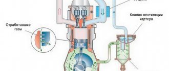
Currently, valves of the poppet type with a stem are used. To improve filling of the cylinder with the combustible mixture, the diameter of the intake valve plate is made larger than that of the exhaust valve. Valve seats made of cast iron or steel are pressed into the cylinder head. During engine operation, valves are subjected to significant mechanical and thermal loads, so special alloys are used for their manufacture. Valves with a hollow stem are sometimes used to improve valve cooling in highly accelerated engines. Sodium melts at operating temperatures and flows in molten form inside the valve, transferring heat from the hotter valve plate to the stem. For better cleaning of the working chamfer from carbon deposits and uniform heat transfer, various mechanisms are sometimes used to rotate the valve. Timing belts can be lower-valve or overhead-valve, but modern engines use only overhead-valve timing when the valves are located in the cylinder head. The valve is held closed by a spring and opens when the valve stem is pressed. Valve springs must have a certain stiffness to ensure valve closure during operation, but the spring stiffness should not be excessive so as not to increase the shock load on the valve seat. Sometimes, to reduce the possibility of resonant vibrations, springs of reduced stiffness are used, but two springs are installed per valve. When using two springs, they must be wound in different directions so that the valve does not jam if one of the springs breaks and its coil gets caught between the coils of the other spring. To reduce friction losses in the timing belt, rollers are now widely used, placed on the levers and pushers of the valve drive.
Rice. Replacing sliding friction with rolling friction by using rollers in the valve mechanism makes it possible to reduce valve drive losses
When the intake valve opens (lowers) the fuel-air mixture (or air) passes through the annular passage between the valve plate and the seat and fills the cylinder. The larger the flow area, the more completely the cylinder will be filled, and consequently, the output indicators of this cylinder during the working stroke will be higher. To better clean the cylinders from combustion products, it is also desirable to increase the diameter of the exhaust valve plate. The dimensions of the valve plates are limited by the size of the combustion chamber in the cylinder head. Better cylinder filling and cleaning is achieved by using more than two valves per cylinder. There are three-valve (two inlet and one exhaust) systems and five-valve (three inlet and two exhaust) systems.
Rice. Four-valve combustion chamber. Application of a gas distribution mechanism with four valves per cylinder in a diesel engine
For the first time, four valves per cylinder were used in 1912 on the engine of the Peugeot Gran Prix car. The widespread use of such a scheme on production passenger cars began only in the 1970s. Now timing belts with four valves per cylinder have become almost standard for engines of European and Japanese passenger cars. Some Mercedes engines have three valves per cylinder, two intake and one exhaust, with two spark plugs (one on each side of the exhaust valve). The engines of some Volkswagen-Audi group cars and a number of Japanese engines use five valves per cylinder (three intake and two exhaust), but with such a number of valves their drive is significantly more complicated.
Rice. Three-valve timing belt. DaimlerChrysler claims that the timing system with two intake, one exhaust and two spark plugs reduces harmful emissions in exhaust gases
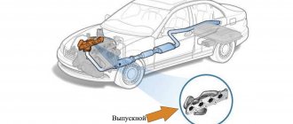
The exhaust valve is a timing element, when opened, exhaust gases are removed (released) from the engine combustion chamber.
Gases are released when the piston in an engine cylinder moves from bottom dead center (BDC) to top dead center (TDC). During engine operation, the exhaust valves are subject to significant thermal loads, as they are constantly in contact with hot exhaust gases. The valve head can heat up within 600-800 degrees during internal combustion engine operation.
After the end of the intake and compression stroke, the main requirement at the moment of ignition of the fuel in the combustion chamber is maximum tightness. The inlet and outlet valves are closed. When the piston has taken on the energy of the expanding gases after the fuel-air mixture has ignited, these exhaust gases must be removed from the combustion chamber. Sealing the chamber is no longer necessary at this stage. The exhaust poppet valve, which is located in the cylinder head (cylinder head), is responsible for removing exhaust gases in the design of the gas distribution mechanism.
During the intake stroke, a vacuum is created, and during the exhaust stroke, increased pressure is formed in the working combustion chamber of the engine. After combustion of the mixture of fuel and air, the exhaust gases leave the combustion chamber through the exhaust valve that opens at the right time. The pressure force allows gases to easily escape from the working chamber. This explains the smaller size of the exhaust valve disc compared to the intake valve disc. During the intake stroke, the vacuum is less powerful than the exhaust pressure. The exhaust gases are practically pushed out through the open exhaust valve.
Effective sealing of the combustion chamber has become possible thanks to the use of poppet valves in the timing structure of modern internal combustion engines. The valve design is simple; the element has a plate and a rod. The chamfer smoothly transitions into the rod, which makes the valve quite durable. The conical shape of the transition significantly reduces the resistance of the exhaust gases when exiting the chamber, and also further improves sealing.
The opening of the exhaust valve occurs due to the force received from the camshaft cam. The valve stem (stem) is located in the valve guide, which is pressed into the cylinder head. The camshaft cam pushes directly onto the valve stem or rocker, which transmits force to the stem. The valve seat is also located in the cylinder head. The valve seat is a recess that is shaped to match the top of the valve disc. The valve plate and valve seat are pressed against each other with filigree precision. This solution allows for maximum tightness when the inlet and outlet valves are closed. The main task is to eliminate gas breakthrough from the combustion chamber.
There is a special groove on the top of the valve stem. The indicated recess is where the “cracker” is installed. This “cracker” is a conical ring that is cut into two equal parts. A solution is needed to secure the valve spring retainer. If the valve is opened by a “push” from the camshaft cam, then the valve is closed by the force of the valve spring. This spring closes the valve, pressing the plate tightly against the seat. Additionally, there is a mechanism that rotates the valve. This is necessary for uniform wear of the valve and cleaning the valve from carbon deposits.
Valve mechanism design
As we have already understood, the internal combustion engine ensures that the valves in the internal combustion engine cylinders admit the combustible mixture, if it is gasoline fuel, or air, if it is diesel fuel, and also release them out. Therefore there are two valves, each of which can open or close at its own time under the pressure of the cams.
The pressure exerted on the rods when it touches the cam in an engine that has combustion of a combustible mixture or air mixed with diesel helps ensure that the rod holding the valve, made of high-quality material, has good movement.
The fact that the movement is smooth on the structure with valves indicates the correct material from which the structure is made.
The presence of the necessary gaps in the metal material of the rod part on which the entire structure rests facilitates the rapid opening and closing of the valves. It turns out that thanks to high-quality material, the engine performs better.
Modern engine parts have the right material, which promotes simplicity in design, they cost little, repairs are rarely required, and the reliability of the design is at the highest level. If a breakdown occurs, the parts should be repaired or completely replaced. We are talking about the camshaft, guide bushings, pusher and spring.
OTHER POSSIBLE TIMING KNOCKS
What should I do if the valves are knocking even after the adjustment has been carried out correctly? In this case, it is necessary to check the condition of the pushers and the camshaft. To do this, remove the camshaft and check:
- The integrity of the camshaft cams and the condition of its supports;
- The gap between the pusher and the seat in the cylinder head;
- The condition of the camshaft bed in the block head. Many VAZ owners are concerned about valve knocking on a cold engine. But the valves knock the same way both on “cold” and “hot”. There are no rods in the timing belt of VAZ engines, as in some GAZ and UAZ engines, so the gap on 2114 practically does not change with heating.
Most likely, the knocking when cold is not due to the valves, but due to the increased gap between the pistons and the cylinder walls in the piston group.
Aluminum pistons expand as they warm up and the clearance decreases. Accordingly, the knocking disappears.
Classification by number of valves
The classic version of the four-stroke engine requires only two valves per cylinder to operate. But modern engines are increasingly subject to new demands in terms of power, fuel consumption and respect for the environment, so this is no longer enough for them. Because the more valves, the more efficient it will be to fill the cylinder with new charge. At different times, the following schemes were tested on engines:
- three-valve (intake - 2, exhaust - 1);
- four valves (intake - 2, exhaust - 2);
- five-valve (intake - 3, exhaust - 2).
Better filling and cleaning of the cylinders is achieved by more valves per cylinder. But this complicates the engine design.
Today, the most popular engines are those with 4 valves per cylinder. The first of these engines appeared in 1912 in the Peugeot Gran Prix. At that time, this solution was not widespread, but since 1970, production cars with this number of valves began to be actively produced.
Intake and exhaust valves: size matters - DRIVE2
If you are designing a cylinder head for maximum power, it will come as no surprise that the main goal is maximum flow. This, among other things, requires the use of larger valves that can be physically installed in the combustion chambers. This requires deciding how best to divide the available space between the intake and exhaust valves. In other words, which is better: a large intake valve and a small exhaust valve, both valves the same size, or a large exhaust valve and a small intake valve? First of all, you might think that a large exhaust valve is the way to go; after all, the exhaust gases undoubtedly occupy a larger volume than the gases drawn into the cylinder through the intake system. However, when it comes to power, another ironclad rule applies: it is easier to empty a cylinder than to fill it. Years of experimentation have shown that the optimal size of the exhaust valve should be approximately 75% of the intake valve, or more precisely, the flow through it should be approximately 75% flow through inlet valve. This rule only applies when the diameters of the valves being combined are equal to the total available space in the chamber, i.e. the valves almost touch each other, as is often the case in racing engines. If valve sizes smaller than the maximum are used and power is not the primary goal, then the balance between intake and exhaust flows is not as critical.
The simplest rule to follow is: if the main requirement is power, then follow the normal ratio of 0.75:1. This rule can be changed in cases where the engine is equipped with a turbocharging or nitrous oxide injection system. These systems require greater exhaust flow and can benefit from an exhaust to intake valve ratio of 0.9:1 (90% exhaust flow) or greater.
Unfortunately, installing larger exhaust valves has a pitfall that does not usually involve upsizing the intake valves. The water jacket inside the cylinder head is located next to the exhaust valve seats. This helps keep valves and seats cool, but often prevents valves from being installed at their maximum size. In addition, thin castings and large amounts of heat (a byproduct of high power) can cause cracks in the seats, and this usually shortens the life of the cylinder head.
Comment. When the designer's primary goal is economy rather than power, the exhaust valve size can be increased to a ratio of 0.75:1 even as the intake valve diameter is increased. When the exhaust port flow is increased, the mileage and service life of the engine will be improved. However, there is a limit here, as with everything. Exhaust valves that are larger than 90 to 95% of the intake valve size provide very little additional fuel savings, and since they use the space normally given to intake valves, power potential will be reduced.
Valves with hollow stem and seat deformation
Some types of particularly powerful engines use exhaust valves with a hollow stem filled with sodium metal. When the valve is heated to operating temperature, sodium melts and turns into liquid. This melt splashes in the bore of the rod and transfers heat from the valve head into the rod. The heat is then transferred through the valve guide and absorbed by the cooling system. The monolithic design of the intake and exhaust valves, with the correct choice of materials, generally ensures good performance characteristics of automobile engines.
The valve is pressed against the seat with a working chamfer, hermetically closing the combustion chamber. The seat is usually formed as a structural element in the cast iron cylinder head - this type of seat is called an integral seat. The seats are usually induction hardened to allow the use of unleaded gasoline. This ensures slower wear of the seats during engine operation. As the seat wears out, the valve sits deeper and deeper into it - it is recessed. In applications where corrosion and wear resistance must be particularly high, plug-in seats are always used. In aluminum heads, valve seats and guides are push-in only. It should be noted that in aluminum heads the operating temperature of the exhaust valve seats is 180°F (100°C) lower than in cast iron. Insert seats are used as a rescue measure when rebuilding severely damaged inline valve seats.
Seat deformation is the main cause of premature valve failure. Deformation of the valve seat can be reversible - as a result of exposure to high temperature and pressure, or irreversible - as a result of internal mechanical stress. Mechanical stress is a force acting on a body that tends to change its shape.
Rod and rocker
The first element is a metal tube with a diameter of 12 millimeters.
It serves to transmit the forces that come from the pusher to the rocker arm. The pipe has pressed-in spherical tips. The lower element rests against the pusher heel, the upper element rests against the adjusting screw. The tips also have holes for lubrication. They pass through the pipe cavities to the valve bearings. The rocker arm is designed to transfer forces from the rod to the valve. The element is made of steel. Above the bar, the rocker arm has a short arm. It is longer above the valve. The short one has a lock nut for setting the thermal gap (applies only to mechanical elements). The rod is located on an individual axis. Two bronze bushings are pressed into it.
PERIODICITY OF ADJUSTING VAZ 2114 VALVES
Car owners have a question: how often is it necessary to adjust the valves on a VAZ 2114 if they do not knock, and is it necessary to make adjustments in this case? According to the factory settings, the valves should be adjusted every 20 thousand km during vehicle operation.
Why carry out adjustment work if the valves of the VAZ 2114 do not knock? The fact is that over time, seat saddles wear out over time. The valve becomes higher and the clearance decreases. And too small a gap threatens loss of power and burnout of the exhaust valves. Before the due date, the clearance in the valves should be checked if knocking occurs and if it is suspected that they are clamped.
A specific knocking sound indicates that the so-called thermal clearances between the valves and their pushers have been broken (that’s what it’s correctly called, not “valve adjustment”). Engine mechanics say this: “the valves are knocking” and “the valves need to be adjusted,” although in reality, of course, these same thermal clearances are adjusted. And the recommendations that I will give here are quite simple and will help you adjust the valves of a VAZ 2114 car with your own hands.
Upper shaft position
How to adjust valve clearances on a VAZ-2114 8 valves
Depending on the design of the power unit, the shaft can be located either above the block or inside it. Let's consider the first case first.
Thanks to the upper position of the shaft, other parts are interconnected with cylinders or pushers.
In the system described, the camshaft, located at the top of the engine, operates thanks to a drive having gears. It can also be seen that the cams and the pusher device located directly above the two gates are connected to each other.
The pusher pressure exerted on the cam causes the part that holds the valve to relax the spring. Next, when the shaft rotates, the spring moves and falls into place, then the valve closes.
ICE with one shaft
There are ICE models that allow the cams to act directly on the levers; they are usually small and are also called fingers. In such an internal combustion engine, the valve material is carefully thought out. There are not many components that play a role in opening and closing the dampers. So, in particular, the movement of the car depends entirely on the cams, which directly act on the short parts that open or close the valves.
As you can see, such a system has few technical difficulties, and besides, such a design is light in weight. There are absolutely no rods in it, which act as a pusher and a rocker arm, which is provoked by the pushing device, exerting pressure on it.
The material of the chain, which contributes to the correct positioning of the shaft on the sprocket, affects the fact that it often hangs.
The core solution to this problem will be the need to add several small sprockets, as well as tension on the short chain. They also use straps that are non-stretchable; their material is rubber. Inside each oil belt there are sprockets that help rotate the camshaft and crankshaft.
Materials from which valves are made
The alloys from which car exhaust valves are made consist mainly of chromium, which provides high heat resistance, with small additions of nickel, manganese and nitrogen compounds. If it is necessary to give the valve special characteristics, it is subjected to heat treatment. If the valve design made of a homogeneous material cannot provide the necessary strength and heat resistance, then it is made welded - from two different materials. After treatment, the junction of the valve parts cannot be distinguished. Valve heads are made from special alloys that are heat resistant, tough, corrosion resistant, lead oxide resistant and highly hard. The heads are welded to rods made of highly wear-resistant materials. In valves designed to operate in particularly severe conditions, carbide materials such as stellite are applied to the working chamfer of the head and the top of the vehicle intake valve stem. Stellite is an alloy of nickel, chromium and tungsten and is a non-magnetic material. In cases where it is necessary to increase corrosion resistance, the valve is aluminized. Aluminizing the working chamfer reduces its wear when using unleaded gasoline. A film of aluminum oxide forms on the surface of the valve, preventing welding of the steel chamfer of the valve to the cast iron seat.
Car valve designs
Car valve heads (auto mechanics often call them poppets) can have different designs; they can be either rigid or elastic. The rigid head is highly durable, retains its shape and has high thermal conductivity. It also has higher wear resistance. The elastic head, in turn, is able to adapt to the shape of the saddle. Therefore, the elastic valve reliably seals the window, but overheats, and bends when fitting into the seat, when the valve adapts to its shape, can lead to its destruction. In the design of valves, a head is widely used, with a small cap protruding above the front surface. Such a valve has a fairly low weight, high strength and heat transfer, and a slightly higher price. Elastic heads are more common on intake valves, while rigid heads are more common on exhaust valves.
Cold air entering hot exhaust valves immediately after stopping the engine can cause serious damage to the valves. On engines equipped with exhaust manifold heads and/or straight-through mufflers, cold air has direct access to the exhaust valves. Sudden cooling may cause warping and/or cracking in the valve. In cold, windy weather, when the wind blows cold outside air directly into the exhaust system, such conditions are not uncommon. Counterflow mufflers with long exhaust pipes and a catalytic converter reduce the risk of this situation.
Throughput and technical losses
Actually, the task of the timing belt, and in particular the valves, is one - to supply the air-fuel mixture as quickly as possible and also remove it from the cylinder block as quickly as possible. I think this is understandable and does not cause any difficulties.
Many engineers thought so too; on the first engines the valves were quite large, they closed large passages into the cylinder heads (which went to the intake and exhaust manifolds). It should be noted that four-stroke engines had exactly 8 valves; this is a kind of classic design.
But a large valve has greater inertia and at high speeds mechanical losses increased. After all, the camshaft cam needed to push this heavy mechanism.
Then they began to decrease. Yes, losses have decreased, but throughput has also decreased.
How to get out of this situation?
We began to increase the number, that is, to make them miniature, but larger. This is how options with 12 – 16 – 20 and even 24 valves appeared. BUT, again, only two survived, the main types are 8 and 16, that is, 2 and 4 valves per cylinder (if we take a 4-cylinder engine).
Where are the valves located?
Human heart valves
Each of these “passers” appeared in its own time and place. And such wonderful harmony allows the cardiovascular system to work clearly and correctly. Moreover, each of them has already received its own name. The exit from the left atrium is equipped with the left atrioventricular valve. Another name for it is bicuspid or mitral. It is called mitral because it resembles the Greek headdress - miter. The exit from the left ventricle, the ancestor of the systemic circulation, is the location of the aortic valve.
It is also called crescentic in another way, because its three doors resemble crescents. The opening between the right atrium and the right ventricle is the location of the right atrioventricular valve. Its other name is tricuspid or tricuspid. The exit from the right ventricle into the pulmonary trunk is controlled by the pulmonary valve, also called the pulmonary valve. The pulmonary valve or pulmonary valve also has three leaflets, which also resemble crescents.
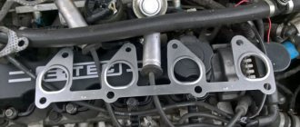
How to distinguish the inlet and outlet channels by size, why do they differ?
What catches your eye is the inaccurate joining of the holes of the manifold channels and the cylinder head. Any “steps” in the channel give rise to parasitic vortices that significantly slow down the flow, so it is necessary to get rid of them. We remove the inconsistencies, while simultaneously modifying the gaskets for the manifold (so that they do not create the notorious steps). I strongly recommend that before removing channel inconsistencies, you do the following - place the collector on the pins. The reason for this is the fastening of manifolds on domestic cars, which allows for some displacement of the planes of the manifolds and cylinder head relative to each other. What this threatens is extremely clear - by slightly shifting the collector during fastening after removing the inconsistencies, we ourselves kill the fruits of our own work. There are enough pins, two per collector - at the edges. We are looking for a place on the cylinder head and manifold where it is safe to drill. We firmly place a metal pin in the cylinder head, onto which the manifold should be placed easily, but without much play - voila, we are guaranteed accurate positioning of the manifolds relative to the cylinder head. Just remember to make a few extra holes in the gasket. I will also note that if the diameter of the intake manifold channel is 1-1.5 mm smaller than the diameter of the cylinder head channel with normal alignment of the channels, then this will not create measurable resistance to the passage of flow, therefore the filigree liner of the channel diameters can be neglected in this case. At the exhaust it is similar, only in reverse - the exhaust channel in the cylinder head may be slightly smaller than the channel in the exhaust manifold. Moreover, because so-called “reverse steps” on the exhaust are used to combat some of the negative phenomena of a tuned exhaust system, but that’s not what we’re talking about now.
List the advantages and disadvantages of bottom valves
The lower valve arrangement was used only in carburetor and gas engines. At the same time, the height of the cylinder head and the entire engine is reduced, and the drive of the camshaft and valves is simplified, but the possibility of increasing the compression ratio is limited (up to 7.5) and the technical and economic indicators of the engine deteriorate.
The lower valves are placed on one side of the cylinder block in one row and are usually alternated in the same way as the upper valves when they are arranged in one row.
Why is it impossible to use lower valves in diesel engines?
In diesel engines, only an overhead valve arrangement is possible, since the relatively small volume of the combustion chamber, resulting from high compression ratios, does not allow valves to be placed on the side of the cylinder. In gasoline engines, both upper and lower valve locations are possible.
What is the main reason for the overhead camshaft?
In modern high-speed engines of VAZ passenger cars, the camshaft is mounted on the cylinder head, which simplifies the kinematic connection between the cams and valves. This arrangement of the camshaft is called an overhead camshaft; it simplifies the cylinder block and reduces noise during operation of the gas distribution mechanism. With an overhead camshaft, the camshaft is driven by a chain or toothed belt.
How is the thermal clearance adjusted when the valves are directly driven from the camshaft?
Thermal clearances between the cams and levers of the intake and exhaust valves must be equal:
– 0.15 mm – on a cold engine;
– 0.20 mm – on a warm engine.
EXECUTION ORDER
— Remove the cylinder head cover with gasket.
— Rotating the crankshaft (with a special wrench) clockwise, align the installation mark (1) on the camshaft sprocket with the installation boss (2) on the camshaft bearing housing. In this case, the piston of the fourth cylinder is at TDC at the end of the compression stroke and both valves are closed.
— Adjust the clearances between the levers and the camshaft cams at the exhaust valve of the fourth cylinder (eighth cam) and the intake valve of the third cylinder (sixth cam).
— To do this, it is necessary to loosen the locknut (3) of the adjusting bolt and, by rotating the adjusting bolt (2), check the required clearance with a flat feeler gauge (1) inserted between the cam and the lever.
— Hold the adjusting bolt in this position with a wrench, tighten the locknut and check the gap again. The feeler gauge should move in the gap with slight pinching.
— Rotating the crankshaft 1/2 turn, adjust the clearances in a certain sequence.
— Replace the cover.
List the advantages of inclined valves relative to the cylinder axis
In the case of an upper valve arrangement, the filling factor can be 5-7% higher than with a lower valve arrangement. This is achieved by increasing the number of valves or placing them at an angle to the cylinder axis.
Why do engines with a belt driven camshaft have special recesses in the pistons?
The crankshaft, which drives the compressor pistons, is connected to the electric motor armature not directly, but through a V-belt drive (belt or rapid compressors). In the presented piston compressors, an electric motor drives a piston through a belt drive, which is capable of performing back-and-forth movements inside the cylinder. This piston, through the inlet valve, sucks air into the cylinder and compresses it to such a pressure that it can push and open the exhaust valve. Depending on the elasticity of the exhaust valve spring, air with a particular pressure is pumped from the cylinder into a special container (receiver), to which the compressed air consumer is connected through a system of valves and pressure gauges using a flexible tube (hose). In two-stage compressors, the second stage of air compression occurs in the same way as the first and at the outlet the air pressure reaches 1.25 MPa.
The compressor is equipped with an automatic pressure valve. When the pressure in the receiver reaches a level higher than the set one, the pressure valve automatically turns off the compressor. If the pressure drops to 0.2-0.3 MPa, the pressure valve turns on the compressor. This allows you to maintain pressure in the receiver in accordance with the established parameters.
At what speed does the camshaft of a two- and four-stroke engine rotate relative to the crankshaft?
The injection pump is exactly the same as the crankshaft, for synchronization and maintaining the injection phase, but the camshaft is 2 times slower.
What is the purpose of the uneven alternation of intake and exhaust ports in the cylinder head?
To obtain the greatest power, it is necessary to fill the cylinders as best as possible with the combustible mixture and clean them of combustion products. For this purpose, the intake valve opens before the piston enters. m.t. at the end of the exhaust stroke, i.e. with advance within 10 ... 31° of crankshaft rotation, and closes after the piston at n. m.t. at the beginning of the compression stroke, i.e. with a delay of 46 ... 83°.
The duration of opening of the intake valve is 236 ... 294° of crankshaft rotation, which significantly increases the amount of combustible mixture or air entering the cylinders. The flow of mixture or air before the piston enters the c. m.t. at the end of the exhaust stroke and after n. The m.t. of the beginning of the compression stroke occurs due to the inertial pressure in the intake manifold due to frequently repeated strokes in the cylinders.
The exhaust valve opens 50 ... 67° before the piston reaches the bottom. m.t. at the end of the stroke, combustion is expansion and closes after the piston reaches the c. m.t. exhaust stroke by 10 ... 47°. The duration of opening of the exhaust valve is 240 ... 294° of crankshaft rotation. The exhaust valve opens earlier because the pressure at the end of the expansion stroke is low and it is used to clean the cylinders of combustion products.
After the piston passes through. m.t. exhaust gases will continue to escape by inertia.
Products for cleaning carbon deposits on valves
Many car owners are interested in the question of how to wash off carbon deposits on valves? Currently, there are a number of chemical products designed directly to remove such deposits. Typically these are additives added to fuel. They are mixed with gasoline, and during the combustion process, together with the air-fuel mixture, they soften this composition, facilitating its combustion along with the fuel. Among these additives, the following are especially popular among car owners:
- Valve cleaner from Liqui Moly Ventil Sauber . The additive is designed to be added to gasoline during the next refueling. Can be used with any type of gasoline. The function of the additive is to remove deposits formed on valves, injectors, carburetor and other elements of the intake tract. It also protects the listed elements from corrosion. Can be used with engines with catalytic converters and turbocharging. Sold in a 250 ml can, which is designed to be dissolved in 75 liters of fuel. The article number for this package is 1989. Its price as of winter 2018/2019 is about 470 rubles.
- Valve and power system cleaner HI-GEAR FUEL SYSTEM & VALVES CLEANER . Another popular product among car enthusiasts. It cleans not only valves very well, but also other elements of the power system. Can be used with any gasoline engines, including those equipped with catalysts and turbochargers. The product is intended for engines up to 2.5 liters. It is recommended to use it as a preventive measure every 3,000 thousand kilometers. Sold in two different jars - 295 ml and 325 ml. The volume of the second can (325 ml) is enough to dilute 40 liters of gasoline. The article numbers for these packages are HG3235 and HG3236. The prices are respectively 440 rubles and 530 rubles.
- Cleaning the engine without disassembling MITSUBISHI SHUMMA ENGINE CONDITIONER . This product was specially created by specialists from the famous Japanese automaker Mitsubishi for cars of this brand equipped with engines with direct fuel injection (GDI). It is recommended to use this product as a preventative every 100 thousand kilometers. However, given that these recommendations are given for Japanese conditions, for domestic roads and gasoline this interval must be significantly reduced. The product is a foam cleaner that is used to treat the internal working surfaces of fuel system elements. Detailed instructions are given on the packaging (in particular, you need to work with a cold engine!). Reviews about the product are very positive. Sold in a 250 ml can. The article number for this package is MZ100139EX. Its price for the above period is about 1300 rubles.
- Wurth valve carbon cleaner . Like the previous one, this product is a foamy detergent composition that is used to wash the contaminated surfaces of the elements of the car’s fuel system. Allows cleaning without disassembling the engine. So, to do this you just need to disconnect a few hoses. Detailed instructions are indicated in the description of the drug. Please note that this product can only be used in combination with a spray wand. One cylinder is enough to treat a four-cylinder engine, and two cylinders are enough to treat six- and eight-cylinder engines.
Also, in addition to factory products, carbon deposits from valves can be removed using phosphoric acid. You can use not its pure composition, but a diluted one. It perfectly removes various deposits, so it will also cope well with carbon deposits. Tested by car enthusiasts in practice! Interestingly, the popular drink Coca-Cola also contains phosphoric acid in small quantities, so it can also be used to remove stains.
Working principle of the intake valve
Timely opening and closing of the intake valve ensures the angular position of the camshaft is precisely synchronized with the same angular position of the crankshaft. That is, the angular position of one strictly corresponds to a certain angular position of the other.
Depending on the engine model, there may be several intake valves per cylinder.
To radically change valve timing, you must purchase a set of sports camshafts
Before the piston reaches its highest dead center, the intake valve begins to open - that is, during the intake stroke, by the time the piston begins to move downward, the valve is already slightly open. Different engine models have their own valve opening advance. The range of fluctuations is 5-30 degrees.
But the closing of the intake valve occurs with some delay, after the piston reaches bottom dead center and begins to move upward. Filling of the cylinder continues even after the start of movement. This occurs due to inertia in the intake manifold.
Shaft together with pushers inside the block
In this position of the valve structure, that is, when it is located inside the cylinder system, the pushing device can act on the part directly touching the valve, which opens it. This is considered a more advantageous position than the previous one, which was discussed above. After all, using a lot of moving particles, the speed of the car is reduced by an order of magnitude. As a result, the intake valve and exhaust valve have less pressure, which reduces the power of the internal combustion engine by an order of magnitude.
Which valve lifter should I choose?
As we noted earlier, there are mechanical, roller and hydraulic elements. When replacing these parts, the question arises of choosing the best type of pusher. So, let's take it in order. Mechanical elements are the simplest and cheapest pushers. Their main drawback is the inability to compensate for the gap. As a result, when the engine reaches operating temperature, they begin to make a characteristic noise. All gaps have to be set manually, through an adjusting bolt. As for hydraulic ones, they automatically set all the gaps.
These pushers are a small chamber where oil enters under pressure. Thus, the adjustment of the gaps is carried out by the lubrication system itself. They are inexpensive, and there is no need to configure them additionally. The only drawback is that the pushers “freeze” at high speeds. But in this case, roller elements based on them are used. Hydraulic roller tappets are designed for a long service life. Thanks to them, you can significantly increase the power of the unit. The dimensions of valve pushers of this type are identical to the standard ones, so you will not have any difficulties with replacement. Now this is the most suitable option among all that are on the market.
How are they arranged?
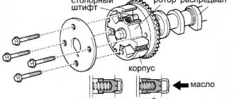
There is a plunger in the body of the hydraulic pusher. The latter has two cameras. This is the discharge and supply chamber, which receives lubricant from the engine during operation. This oil then passes through the ball valve to the discharge part. To compensate for gaps with high precision, the volume of liquid is dosed into the plunger. It is pressed out of the pusher housing by a spring. Thus, the thermal gap is restored to normal values. When the intake or exhaust valve opens, oil is in the discharge chamber. The ball valve returns some of it back to the feed chamber. When the pusher body moves upward, a certain fluid pressure is created. The oil prevents the plunger from moving relative to the body. When the valve closes, lubricant leaks from the plunger side. However, with a new discovery, this disadvantage is compensated through the discharge chamber. When the engine starts, the elements of the gas distribution mechanism gain operating temperature. The metal expands, and the volume of oil in the discharge chamber decreases. Thanks to the coordinated operation of the mechanism, the gaps between the valves are compensated. The work also involves elements such as a rocker arm and a valve rod. Below we will look at what they are.
ENGINE KNOCKING IN FRONT WHEEL VAZ CARS
In front-wheel drive VAZ cars, the engines may have different digital indices, since the engines are installed on different car models. But basically all power units have the same circuit diagram, but they may differ:
- 8-valve or 16-valve cylinder head;
- Piston diameter;
- Carburetor or injection fuel system;
- Minor design features (different sensors, collector configuration, etc.).
In particular, the VAZ 2114 car is equipped with an 8-valve 4-cylinder engine with a volume of 1.5 liters of the VAZ 2111 model, with a fuel supply system of the “injector” type (distributed injection). Exactly the same internal combustion engine (ICE) is equipped with the VAZ 2115 and VAZ 2113.
Various knocking noises can occur in an internal combustion engine, and it is not necessarily the valves that are knocking. Knocks can occur:
- In the piston group,
- In the crank mechanism;
- In the gas distribution system;
- In attachments (water pump, generator, etc.).
Why does the engine knock, what could be causing the knocking:
- insufficient amount of oil in the oil system crankcase;
- wear of parts due to long-term use;
- manufacturing defects;
- engine overheating;
- operation of the motor at constant maximum loads.
Knocking in the VAZ 2114 engine has a different character; determining the cause is sometimes difficult even for technicians who have some experience in repairs. But there are characteristic sounds that are identified quite easily:
- a sharp “dry” metallic sound, clearly audible when you sharply press the gas pedal. This is how the crankpins (bearings) of the crankshaft knock. This is a serious knock, at a minimum, it requires crankshaft grinding;
- the sound is medium in tone; when the speed increases, it seems that something is rolling around inside the internal combustion engine. This is how the pistons usually knock;
- single clicking sound. As the speed increases, it seems to merge, and is similar to the sound of a working sewing machine. This is how parts of the gas distribution mechanism (camshaft, pusher) usually knock.
How do valves knock, how to determine it? The valve knock is usually quite sharp, clicking, and high-pitched. He can knock not just one, but several at once. To understand the cause of various noises in the gas distribution mechanism (GRM), you need to have at least a little idea of its structure. The VAZ 2114 timing belt consists of the following elements:
- camshaft.
- timing gear.
- Timing belt.
- Pushers.
- Adjusting washers.
- Inlet and exhaust valves.
Engine having one distributor shaft
There are internal combustion engines that do not have pushrods, so a single type camshaft is used to open and close the valves. This design is called a single camshaft engine. There the valve parts are placed in the head. The design has few moving parts, which is what contributes to its reliability, allowing it to operate even when the vehicle’s speed is at the limit. Moreover, the material from which spare parts are made is metal (special alloy).
For more efficient operation of the motor, there must be free space between the elements - a gap. If there are no clearances between the bolt foot, cam or rocker arm, then the system will wear out, causing serious damage.
It is also worth noting that excessive clearances will cause the valve to open prematurely and close later. Thus, the power of the internal combustion engine will be reduced, and under high valve pressure the operation will be noisier.
If the gap is small, then the pressure will become less, this will lead to the fact that the shutter stroke will become very difficult, thereby the car will lose power.
There are internal combustion engines that operate automatically, adjusting the valves themselves to the desired action. To do this, you need a plentiful amount of lubricating fluid, because it is under its pressure that the valve system will operate.
Inlet and outlet valve - differences
The main difference between the intake valve and the exhaust valve is the diameter of the plate: the intake valve has a larger one. Why? Because the absorption of air from the atmosphere into the cylinder under the influence of vacuum occurs at a lower speed than its expulsion from the cylinder by the piston.
It’s simple: the amount of air (or air-fuel mixture) is the same, but the speed is different. Accordingly, where the speed is lower, the hole is wider, and the plate covering it is larger in diameter.
All this is true for those valve mechanisms where there are equal numbers of intake and exhaust valves - one or two each. However, there are engines with an odd number of valves: two intake + one exhaust or three intake + two exhaust. Here the opposite is true: the diameter of the exhaust valve plates will be larger than that of the intake valves, because the manufacturer compensated for the low suction speed by adding one “extra” hole, and not by increasing the diameter. You can read more about the relationship between valves and cylinders in the corresponding article.
The second important difference in valve design is their operating temperature. Intake valves operate at 350-500 degrees, but the exhaust valves are harder - hot exhaust gases heat them up to 700-900 degrees. Therefore, accordingly, exhaust valves are often made more heat resistant.
KnowCar is a clear encyclopedia on the design of cars, where complex things are described in simple language, with illustrations and videos, and articles are sorted into sections. The encyclopedia is in the process of being filled. If you have questions or suggestions, please contact the team. All contact details are at the bottom of the site.
Double spring
In four-stroke gasoline and diesel engines, the valves are located in the cylinder head. Only a mixture of air and fuel passes through the intake valves, so they are exposed to lower temperatures than the exhaust valves. The inlet valve plate has a larger diameter than the exhaust valve, since the inlet pressure is less than the outlet pressure. Engines of different models differ in the number of valves. Engines with two or more intake valves tend to have better cylinder filling. An additional intake valve increases the flow area of the intake channels, therefore, more air-fuel mixture enters the cylinder. The same applies to the exhaust valves: two valves on the exhaust allow larger exhaust ports, which makes it easier for exhaust gases to exit the cylinder. The valve is subjected to very significant loads even during normal engine operation. To increase the valve's resistance to wear, burning and corrosion, its surface is subjected to special treatment. For example, intake valves are made of steel with chromium or silicon to increase their wear resistance and corrosion resistance, or magnesium and nickel for increased strength. Exhaust valves are made of nickel-based alloys. The valve consists of two parts: a rod and a plate. The valve is installed in a hole in the cylinder head. The plate fits tightly to the saddle. During operation, the cylinder head heats the seat. Some of the heat is transferred to the valve stem, and from it to the guide sleeve, so the stem is the coolest part of the valve. The valve seat and guide are cooled by fluid flowing through the jacket around the intake ports. When opening and closing, the valve rotates at a small angle, so each time it sits in a new place.
If you are planning to increase engine power by replacing the intake and exhaust valves, then first of all you need to find out which one should be larger.
In this article we will tell you which valve is larger, the intake or exhaust, so that in the future you can know whether the necessary parts are in the engine.
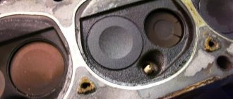
Determining valve burnout without removing the cylinder head
The first step is to determine which cylinder is not working. The testing methods are in many ways similar to diagnosing faulty spark plugs. To check, you should start the engine, after which, with the engine running at idle speed, you will need to remove the caps from the spark plugs one by one.
After removing each spark plug cap, you need to carefully monitor the idle speed and the overall stability of the engine. If the engine starts to rev more strongly or stall, then the cylinder from which the cap was removed is working. If after removing the cap the engine operation does not change or the speed changes only slightly, then the problem cylinder has been detected.
Then you need to unscrew the spark plug on the inoperative cylinder and replace it with a known good one, and also check the high-voltage armored wire of this cylinder for functionality. It would also be a good idea to check the ignition coil, etc. Subsequent starting of the engine will show whether the problem lies in the elements of the vehicle’s ignition system or whether further diagnostics are necessary.
If the nature of the engine’s operation does not change after installing the working spark plug, replacing the high-voltage wire and checking other components of the ignition system (the engine continues to rev), then there is a high probability of more serious breakdowns:
- valve burnout;
- CPG malfunctions;
Burnout of the valves means that compression in the cylinder is reduced due to a violation of the tightness of the combustion chamber (leakage during the fit of the intake or exhaust valve, destruction of the disc and/or valve seat). Wear of the cylinder-piston group and piston breakage also lead to low compression in the problem cylinder. Also, the cylinder may not work due to stuck or broken piston rings.
Now it is necessary to localize the malfunction, that is, to accurately determine the burnout of the valve or identify problems with the CPG. The most common way to determine burnt valves is to measure the compression in the cylinders.
Low compression clearly indicates a malfunction, but one caveat should be taken into account. It will not be possible to establish a burnt-out valve and rule out problems with the CPG only based on the compression indicator. The fact is that compression in the engine can decrease both as a result of a burnt-out valve, and due to broken piston rings, as well as a number of other defects. For this reason, in parallel with the compression measurement, additional engine diagnostics should be carried out.
- The easiest way to determine valve burnout after you have measured the compression in the cylinders is to pour several “cubes” of engine oil through the spark plug well. Then the compression must be measured again. An increase in compression in the cylinder after adding oil will indicate that an oil film has formed, acting as a “seal”. This phenomenon is typical in the case of piston wear. If the compression indicator has not changed, it means that the valve has burned out, since the oil in the cylinder in this case will not affect the compression in any way.
- Also, to determine whether the valves are burned out, you should inspect the spark plug on the problem cylinder. A clear sign of valve burnout is that the spark plug is completely dry, that is, it does not have a characteristic oil deposit. There may also be smoke or air coming out of the engine breather. The intensity of smoke production directly depends on the degree of wear of the CPG.
As for breakdowns that are associated with the piston, in this case the spark plug is covered with oil, and the appearance of bluish smoke can be observed from the breather. Note that oil on a candle is an indirect sign. Even if the spark plug is dry or covered with a slight soot, but smoke comes from the breather, then this symptom indicates problems with the piston or piston rings. On new engines with low mileage, there is a high probability that.
Let us add that the appearance of engine oil that comes out through the breather also indicates a malfunction of the partitions between the piston rings. Taking into account the above, you can accurately determine why the compression in the engine has decreased, identify problems with the cylinder-piston group, or determine burnout of the timing valves.
Why is it necessary to regulate?
There are only two reasons. This is their “squeezing”, when the thermal gap disappears between the camshaft cam and the pusher. And vice versa, increasing the gap. Both cases do not bring anything good. I will try to tell everything in more detail on my fingers
Why does the valve clamp?
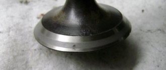
This happens very often among those who drive on gas (natural gas engine fuel). The widest part of the valve is called the plate (it has a chamfer along the edges), it is this that is located in the combustion chamber on one side, and on the other it is pressed against the “seat” in the head of the block (this is the part where the valve goes, thus sealing the combustion chamber).
From high mileage, the “saddle” begins to wear out, as well as the chamfer on the “plate”. Thus, the “rod” moves upward, pressing the “pusher” to the “cam” almost tightly. This is why “clamping” can occur.
THIS IS VERY BAD! Why? Yes, everything is simple - thermal expansion has not gone anywhere. This means that in the “clamped” case, when the rod heats up (elongation occurs), the plate will slightly come out of the seat:
- Compression drops and power drops accordingly.
- The contact with the block head (with the seat) is broken - there is no normal heat removal from the valve - to the head
- When ignited, part of the burning mixture can pass past the valve directly into the exhaust manifold, melting or destroying the “plate” and its chamfer
Well, a secondary reason is that this mixture can negatively affect the catalyst.
It must be remembered that the “inlet elements” are cooled by the newly incoming fuel mixture!
But the heat removal of the “exhaust” depends on how tightly it is pressed against the “saddle”!
Increasing the gap
There is another situation. It is typical for gasoline engines. On the contrary, the “thermal gap” increases. Why does this happen and why is it bad?
Over time, the plane of the pusher, as well as the surface of the camshaft cams, wear out - which leads to an increase in the gap. If it is not adjusted in time, it increases even more from shock loads. The engine starts to run noisily, even when “hot”.
Engine power decreases due to irregular valve timing. To put it in simple terms, the intake valves open a little later, which does not allow the combustion chamber to be filled normally, and the exhaust valves also open later, which does not allow the exhaust gases to escape normally.
Now let's watch the video version of the article.
And here I end, I think my materials were useful to you. YOURSINCERELY AUTOBLOGGER
75,00
Similar news
8 or 16 valves, which is better? And what exactly is the difference? Details
Turbocharged or naturally aspirated engine. Which is better and more reliable?
Engine torque and power. What's more important? A few words about .
Express delivery to all cities of Russia!
- Price:
Check the price
Equipment used for commercial and industrial purposes must meet increased requirements for quality and functionality. Such units are resistant to intense loads and continuous operation in difficult conditions. Such operating characteristics, of course, negatively affect the degree of wear of components, and it is extremely important to promptly diagnose and repair systems and components of machines, be it a truck, a piece of special equipment, a bus or other equipment.
The key aspect of effective repairs is experienced craftsmen and high-quality spare parts. If you want to ensure long-lasting and trouble-free operation of your equipment, please contact. Our team will not only help you find and order any spare parts for the Cummins engine or other components for equipment, but will also promptly repair damage and engine malfunctions.
Professionalism and rich work experience,
Use and sale of original spare parts with a guarantee of up to 12 months,
Individual approach to every customer,
Favorable prices and special terms of cooperation for wholesalers.
Contact our manager at the phone numbers listed on the website (the call is free throughout Russia) or write to us on the website. We accept orders from customers from any region of Russia and provide prompt delivery using trusted transport companies. The transparency of our work and the excellent quality of products will pleasantly surprise you - contact us and take care of the work of your technology park!
Causes of burnout
Valves burn out for various reasons, including:
- factory defects or low-quality spare parts;
- incorrect valve adjustment or malfunction of hydraulic compensators;
- valve wear (valve stem or guide bushing);
- early or late ignition;
- lean mixture.
No one is immune from purchasing defective and low-quality spare parts, so buy spare parts from trusted sellers who value their reputation. If the valves are adjusted incorrectly (they are tightly clamped), the engine operation will be noticeable by the characteristic “tractor” sound. In this case, due to non-compliance with the thermal clearance, the valve overheats, which will invariably lead to its burnout.
If the ignition is set incorrectly, combustion of the combustible mixture occurs when the valve is open and leads to its malfunction. A lean mixture is dangerous because the combustion temperature of the combustible mixture increases, which leads to overheating and burnout.
Since this DTC indicates a problem with the circuit, you will use
- Connector and Harness Inspection - Make sure the VVT solenoid valve connector is in good working order with no bent or loose pins, corrosion, or water ingress. Make sure the connector is securely installed. Check the wiring harness for damage, fraying, exposed or broken wires. Repair as needed.
- Voltage Check - With the engine running, you should have a minimum of 13.4 volts at the battery. Check the VVT solenoid valve check probe, usually located in the cylinder head or valve cover, and check the battery voltage.
- If the voltage is incorrect, suspect an open circuit between the ECM and the valve. Disconnect the connector and recheck the battery voltage. If not, suspect an open circuit between the ECM and the valve. Inspect the wiring harness and repair if necessary.
- If the voltage is correct, suspect a grounding problem. With the key turned off and the engine off, disconnect the VVT solenoid valve connector and the ECM connector. From the VVT solenoid valve connector, check both pins for short to each other and short to ground. You should measure the infinite resistance to ground and across the pins. If incorrect, suspect a short circuit. Repair as needed.
- VVT Solenoid Valve Check
- Check the resistance between the solenoid valve contacts. You should measure between 5 Ω and 15 Ω, depending on the manufacturer and temperature. Check your manual for the correct specification. If incorrect, replace the valve.
- Check resistance between contacts and ground. You must measure the infinite resistance to ground. If incorrect, replace the valve.
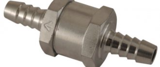
Why do you need a water check valve and how to install it correctly?
Check valves must be installed on any pipeline. Without them, many equipment and pipeline fittings will not be able to function normally and will most likely soon become unusable. Before purchasing pipeline fittings, you need to find out why you need a check valve for water and how to install it correctly. Let's try to look at the main issues in this article.
Purpose
The check valve is designed to protect the pipeline from reverse flow of the working medium and the effects of pressure. The pumping station or individual water supply system may suffer the most from a change in the direction of movement of the working environment. The check valve is installed next to equipment sensitive to changes in flow direction and solves several problems at once:
- Protects the pipeline system and equipment from sudden pressure surges;
- Prevents the working environment from changing the direction of flow. Many devices and types of pipeline fittings are unidirectional and when the flow changes, they almost instantly become unusable.
- Stabilization of pressure in the system. This is especially important in apartment buildings where the pressure in the pipeline is not enough to supply water to the top floors.
A non-return valve installed on the sewer system plays a very important role. It prevents the movement of wastewater into the apartment even if the pipes are seriously clogged.
Design and principle of operation
The principle of operation of the valve is extremely simple. The device allows the working medium to flow freely in a given direction, and when it changes, it automatically closes the pipeline, preventing the flow from changing its direction. The valve is actuated by the force of the flow itself.
The device consists of three main elements:
- Metal housing with two pipes for connection to the pipeline;
- Locking mechanism with sealing gasket;
Volatile automatic valves operate reliably and reliably protect the pipeline from backflow of the working medium.
Kinds
There are several types of check valves designed for different piping systems and operating conditions. Depending on the type of locking mechanism, valves are divided into the following categories:
- Lifting. The locking organ moves in a vertical plane. When liquid moves from bottom to top, the flow rests against the valve cover, holds it and flows freely. When changing the direction of movement, the water from above presses on the lid, closing it and blocking its path in the opposite direction.
- In a butterfly valve, the lid flips back and clears the passage, and when it moves back, the liquid locks it.
- Ball valve, where a ball acts as a locking organ.
- Double-disc consists of two leaves. In the absence of back pressure, they fold, and when the direction of flow changes, they open and block the gap in the pipe.
Lifting valves have gained the most popularity. Thanks to their simplicity and reliability, they have become an integral part of almost every household pipeline.
Selection and installation
When choosing a valve, only the diameter of the pipe and the expected pressure in the system matter. When purchasing, you should pay attention to the quality of the device (no defects).
Before installation, you must select the correct location for the valve:
- In wells equipped with vacuum pumps, fittings are installed at the outlet to prevent water from draining under its own weight;
- Surface pumps require the installation of valves in front of the accumulator;
- In sewer networks, valves are installed before each additional source of wastewater.
A check valve is a fail-safe safety device that can help avoid pipeline accidents and breakdowns of expensive equipment.