REPAIR OF BRAKE CYLINDER.
Brake cylinders are designed to transmit the force of compressed air entering them during braking to a system of rods and levers, through which the brake pads are pressed against the wheel tires.
The repair of the brake cylinder is carried out by a rolling stock mechanic of the 4th category.
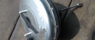
Fig.9 Brake cylinder
The brake cylinder consists of a housing 1, front 6 and rear 12 covers, a piston 2 connected by a pin 4 to a tubular rod 5. The piston is sealed with a cuff 11 made of oil-freeze-resistant rubber installed in an annular recess. To lubricate the working surface of the cylinder there is a felt ring 10, impregnated with brake grease and expanded by a leaf spring. In the neck of the front cover there is a filter 7, which, when the brake is released, is closed with a rubber washer 8, placed on the rod. The thrust ring 9 serves to hold the release spring 3 in a compressed state and to conveniently remove and install the piston assembled with the front cover into the cylinder. To remove moisture and condensation, a groove has been made in the lower side part between the body and the front cover since 1971 during the manufacture of the cylinder. In brake cylinders manufactured before 1971, a moisture drain hole with a diameter of 10 mm is drilled in the housing at a distance of 35 mm from the front flange.
The brake cylinder body must not have cracks or chips. The inner surface of the brake cylinder must be cleaned and inspected - rust is not allowed (rust is removed with sandpaper). ZhT-79L lubricant must be applied to the inner surface of the brake cylinder before installing the repaired piston unit into it. The strength of the brake cylinder fastening to the car frame is checked.
The brake cylinder is secured to the car with six M16 bolts with spring washers and slotted or castle nuts and secured with cotter pins that fit into the hole of the bolt and the slots of the nuts. It is allowed to fasten the brake cylinder with M16 bolts with lock washers, nuts and lock nuts.
Install the piston assembly on the device, compress the spring with the front cover. Unscrew the bolts securing the rod head and remove the head. Release the spring and remove the front cover. Remove the thrust ring, knock out the pin, separate the rod from the piston. Clean and wipe the piston assembly parts. Remove rust from the surface of parts. Clean, rinse, wipe the filter and dust seal.
When repairing the housing and front cover of brake cylinders made of gray cast iron grade SCh-15, it is allowed:
— welding of no more than two cracks in the flanges of the front cover and the brake cylinder body with a total length of no more than 60 mm, if these cracks do not extend to the working surfaces;
— Welding of broken parts of the housing flanges and the front cover of the brake cylinder, provided that the broken part covers no more than two adjacent bolt holes and the number of broken parts is no more than two;
— welding a bushing with a wall thickness of 4-6.5 mm to the neck of the front cover.
Welding should be performed with heating to a temperature of 550-600 0 C. Heating before welding and subsequent cooling after welding should be performed slowly at a speed that prevents the appearance of cracks in the weld metal and heat-affected zone.
When repairing a steel brake cylinder, it is allowed to weld cracks that appear in the mounting flange if there are no more than four such cracks, and no more than two are located in adjacent narrow areas. The reinforcing lining must be made in the form of a strip and welded with a continuous seam. The lining should be made from steels St3sp, 09G2, 09G2D, 10G2BD or other low-alloy steels with a carbon content of up to 0.14%. It is necessary to use pre-calcined electrodes of the UONI-13/45 brand or similar in quality to the resulting weld metal. The welding technology must prevent deformation of the mounting flange under the influence of welding heat.
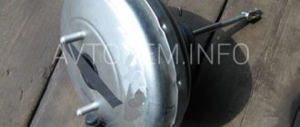
Fig. 10 Brake cylinder No. 188B
1 – body; 2 – piston; 3 – release spring; 4 – hairpin; 5 – tubular section rod; 6 – front cover; 7 – filter; 8 – rubber washer;
9 – thrust ring; 10 — felt ring; 11 – cuff made of oil-freeze-resistant rubber; 12 – back cover.
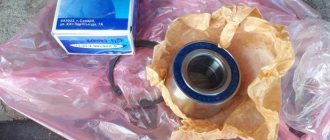
Repair kit for rear brake cylinder VAZ 2110
The peculiarity of the VAZ-2110 brake system is that the circuits are divided diagonally; it is this mechanism that ensures a high level of driving safety.
The brake located in front and the left one at the rear operate from a single hydraulic drive, the remaining 2 are also from a joint, but different one. Thus, if one circuit of the brake system has failed to function, you can solve the problem by replacing it.
Why is the rear brake mechanism acting up?
The hydraulic drive built into the VAZ-2110 combines in its internal design a booster and a dual-circuit pressure controller designed to control the rear brakes. If the rear cylinder is not working correctly, problems can provoke and create an emergency situation at any time when the vehicle is moving along the roadway. To prevent this from happening, the part should be repaired in a timely manner.
There is nothing surprising in replacing an old type of rear brake cylinder (RBC) with a new one; nothing lasts forever. Auto parts stores offer car enthusiasts the opportunity to purchase parts from the best manufacturers that will last a long time and guarantee safety on the road.
Repair kit for rear brake cylinder VAZ 2110
Usually, when the rear brake cylinder fails on VAZ 2110 cars, you can observe a decrease in the level of brake fluid in the reservoir.
This occurs due to a violation of the tightness of the piston and its rubber. To fix this problem, you need to replace the cylinder with a new one. There is nothing complicated in this procedure, and to perform it you will need the following tools: A 10-point socket with a ratchet and a wrench A special wrench for unscrewing the brake pipes (the so-called split wrench) First, you need to remove the brake drum and rear pads, since access to the cylinder cannot be obtained otherwise. After this, from the reverse side we unscrew the tube that fits the cylinder with a split wrench: To prevent the brake fluid from leaking out, you can plug its end for a while. Then we take the head with a knob and unscrew the two fastening bolts, again from the rear side, as is more clearly demonstrated in the photo below: After which you can safely remove the rear brake cylinder of the VAZ 2110 from the outside, since it is not attached to anything else.
The price of a new part produced by VIS is about 300 rubles per piece. If you change in pairs, then naturally you will have to pay about 600 rubles. Installation is carried out in reverse order. If, after installing everything new, the braking efficiency has decreased, and when you press the brake pedal, it sinks more than necessary, it is necessary to pump the fluid through the system. Leaking brake cylinders of the rear wheels of VAZ 2108, 2109, 21099 cars are a very common malfunction.
Repair of the rear wheel brake cylinder of VAZ 2108, 2109, 21099 cars
Leaking brake cylinders of the rear wheels of VAZ 2108, 2109, 21099 cars are a very common malfunction.
The reason is wear of the sealing rings (cuffs) on their pistons. By purchasing a cheap repair kit for rear brake cylinders (several rubber rings), you can carry out simple repairs and extend their performance for a while. The only condition is that the inner surface of the brake cylinder (mirror) is in good condition. Corrosion and risks on the mirror will not allow for quality repairs. In this case, it is necessary to replace the rear wheel brake cylinder with a new one.
Required Tools
- 10 mm spanner
- 12 mm spanner
- 13 mm spanner
- a special wrench for unscrewing the brake pipe
Preparatory work
— place the car in the pit, the handbrake should be lowered, the wheels should be supported
— loosen the rear wheel bolts, jack it up and remove it
— weaken the tension of the parking brake cable (handbrake)
To facilitate this operation and improve access to the parking brake actuator adjusting nut, you can disconnect the connection between the muffler and the resonator. Using a 13 mm wrench, unscrew the nuts securing the clamp at their connection and disconnect it.
Using a 13 mm wrench, unscrew the lock nut on the handbrake rod with another 13 mm wrench while holding the adjusting nut. Using the same wrench, unscrew the adjusting nut while holding the handbrake rod with pliers.
- unscrew the guide pins of the brake drum and remove it
If the pins do not turn away, lightly tap them with a hammer. If the drum cannot be removed, we also tap it with a hammer on all sides through a wooden spacer. We clean its mounting hole from contamination and treat it with a penetrating liquid.
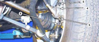
— alternately remove the thrust ends of the brake pads from the slots in the cylinder pistons
— lightly press the brake pedal so that the pistons move out of the brake cylinder as far as possible
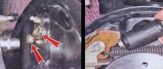
— unscrew the fastening of the brake pipe to the cylinder
We use a special key for this. After disconnecting, put a rubber cap on the tip of the tube to prevent brake fluid from leaking out.
— unscrew the two bolts securing the brake cylinder to the brake mechanism shield and remove it
We use a 10mm spanner.
If the tip of the brake pipe is rusty and when you try to unscrew it, it may break off along with the brake pipe, then unscrew it after removing the brake cylinder. At the same time, hold the tip with a “10” key or a special key, and rotate the brake cylinder itself.
Replacement of sealing rings (cuffs) of the rear wheel brake cylinder of VAZ 2108, 2109, 21099 cars
— Remove the rubber boots from both pistons of the brake cylinder
— Using pliers, pull the pistons out of the cylinder body
The operation requires considerable effort, since it is necessary to overcome the resistance of the steel rings of the automatic gap maintenance device installed on each of the pistons.
If it is not possible to pull the pistons out of the cylinder, then we simply knock them out of it. We drive one of the pistons into the cylinder with a hammer, the second one falls out. We put on the mandrel and knock out the second piston.
— We remove the old cuffs and install new ones
You can use a screwdriver or an awl for removal and installation. Before installation, lubricate the rubber cuffs, pistons and cylinder mirror with brake fluid.
— We hammer the pistons into the cylinder and reassemble in the reverse order
Notes and additions
— After repairing the brake cylinder, you should bleed both circuits of the vehicle’s brake system to remove air from the brake system. And adjust the handbrake.
TWOKARBURATORS VK -More information on the topic in our VKontakte group
Removing air by pumping
If during the repair process a lot of fluid leaks from the circuit and air bubbles form in the system, the repaired hydraulic cylinders will not be able to function normally. The circuit must be pumped using the instructions:
- Place a spanner and a transparent tube directed into the bottle onto the discharge fitting.
Before removing air and during the bleeding process, the tank is replenished with new fluid. A working substance filled with bubbles and poured into a bottle cannot be reused. Upon completion of the repair, check the operation of the brakes while driving.
Working brake cylinder - repair and replacement
If the expression “the main thing is to stop on time” in everyday communication concerns moral principles, then in the context of motor transport this expression can affect the material aspect of the life and health of the motorist.
There are no secondary units in the car, but the braking system should be a priority in car maintenance and repair. In the operation scheme of hydraulic brakes, the main ones are both the main and the working brake cylinders. Let's look at the operating principle, design, diagnostics, repair and replacement of this unit using the example of a common VAZ car.
Principle of operation
The brake fluid coming from the main one under pressure acts on both pistons in the working cylinder, which, in turn, compress or expand the brake pads, which leads to braking. The front brake circuit is disc, while the rear brake circuit in many cars is drum type.
- Front calipers.
- Pipe supplying hydraulic fluid to the front wheels.
- Rear pipeline.
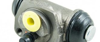
- Rear wheel rollers.
- Tank.
- Main roller
- One of the pistons.
- Stock.
- Pedal.
Device
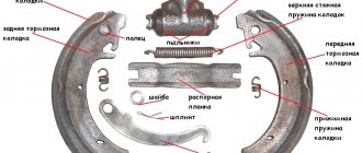
The design of the front caliper and the rear brake cylinder of a VAZ car differ in the appearance of the body and main parts. The disc brake device consists of the following main parts:
1 - Piston. 2 - Boot. 3 - Sealing collar. 4 - Caliper body. 6 - Air fitting. 7 - Springs that press the pads. 12 - Pads.
The drum brake uses the following parts:
2 - Bleeding fitting. 3, 11 - Anther. 4, 10 - Piston. 6, 9 — Piston seal. 7 - Housing.
Diagnostics
The following signs will tell the motorist that repair of the brake wheel cylinder is approaching:
- Uneven operation of the wheels when braking, which can result in the car skidding. This is a sign of a stuck piston, which can cause the use of low-quality fluid or air entering the system.
- The indicator light is triggered when the fluid in the tank is critically low, or this is detected during a visual inspection, which indicates a possible leak of hydraulic fluid from worn cuffs or leaky pipes.
- The pedal is pressed with great effort, this can happen for all the reasons described above.
A stuck piston and a stiff pedal are not yet indicators for repairing and replacing working cylinders. You should pay attention to the thickness of the pads; if their wear has reached its maximum, this can cause the pistons to jam, since they practically do not work.
Initially, completely replacing the hydraulic fluid or bleeding the brake system may also help correct these problems. If these actions do not lead to a positive result, it is necessary to repair the working brake cylinder; fortunately, there is a repair kit for the working brake cylinder on sale, the set of which, depending on the make of the car, includes: cuffs, piston, boot and other components.
Operating principle of the brake system
The operating diagram of the hydraulic drive of this system is simple: a depressed pedal that acts on the vacuum booster (if provided), or directly on the main brake cylinder, the latter, creating pressure on the hydraulic fluid, sends it through the pipes to the working rollers that release the brake pads.
It follows that the main unit in this diagram is considered to be the main cylinder; to understand how to repair the main brake cylinder with your own hands, you need to study all its components.
Symptoms of a faulty master cylinder
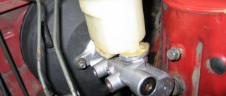
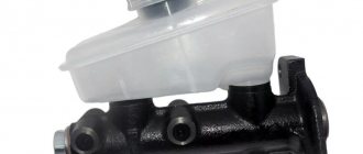
Problems that arise with the brakes while traveling are considered critical and must be corrected immediately. The culprit of the malfunction is often the main cylinder, installed in the engine compartment and rigidly connected to the pedal. To find out the cause of the breakdown and repair the unit yourself, you need to know the structure of the brake master cylinder (MBC) and its principle of operation. During the diagnostic process, it is necessary to distinguish and filter out problems with other elements of the system.
How does the GTZ function?
The unit consists of the following parts:
- metal housing with holes for supplying brake fluid, pedal rod and connecting the expansion tank;
- 2 pistons with rubber seals;
- 2 return springs;
- guide bushings;
- end plug with gasket.
An expansion tank is attached to the top of the main distributor body, where excess fluid goes through compensation holes. Inside, the element is divided into 2 cylinders with separate pistons standing on the same axis.
The blind end of the housing is closed with a threaded plug; on the other side there is a flange for attaching to the vacuum booster. The brake pedal rod is attached to the first piston. The brake circuit pipes are connected to the lower holes - separately for the front and rear wheels.
The operating principle of the master brake cylinder looks like this:
- When you press the pedal, both pistons simultaneously move forward and push fluid into the circuit tubes. Under its pressure, the wheel cylinders are activated, compressing the pads on the discs.
- Part of the liquid that does not have time to pass into the tubes flows into the expansion tank through special bypass holes.
- When the driver releases the pedal, the springs push the pistons back, returning them to their original position. Liquid from the tubes and reservoir refills the cylinders.
- To compensate for the expansion of the liquid (for example, from heating), another pair of holes is provided leading to the expansion tank.
Note. The GTZ acts in conjunction with a vacuum booster (not shown in the diagram), which helps put pressure on the pistons. This allows the system to respond faster and make the driver's actions easier.
Symptoms of problems
The general technical condition of the car (including the brake system) can be checked using a personal diagnostic adapter - a car scanner. These types of devices are widespread and have a wide price range. We would like to draw your attention to the budget model of Korean production Scan Tool Pro Black Edition.
At a cost of about 2 thousand rubles. This scanner is capable of fully diagnosing your car (engine, gearbox, transmission, abs, srs and much more), which will pay for itself in 1-2 trips to the service station. The adapter is quite easy to use, has Russian-language software and is compatible with most cars produced in 1993. The device will also be useful when buying a used car, as it can show its real mileage and VIN.
The fluid brake system consists of many parts that can become unusable: pipes, wheel cylinders, calipers, drums and pads. Typical signs of a faulty master cylinder:
- After pressing the pedal, the car stops slowly. The reason is that the cuffs of one or two pistons have lost their tightness - they have cracked or “floated”.
- To slow down, you need to press the brake pedal hard. The phenomenon occurs due to swelling of the rubber of the piston seals.
- The brake pedal travel is too short. The fluid inside the cylinder has nowhere to go because the compensation hole is clogged. Another option is that the passage is blocked by a swollen rubber seal.
- A common symptom is pedal failure, the brakes coming on at the end of the stroke. This indicates complete wear of the cuffs; as a result, liquid penetrates behind the piston and rushes into the expansion tank - the cylinder “bypasses.”
- The pads do not release the brake discs and drums and get very hot when driving. Options: one of the pistons is jammed or the bypass hole is clogged.
Disassembly and assembly of wheel cylinders
Disassembly and assembly of VAZ 2107 wheel cylinders
Rice. 7–16. Wheel cylinder: 1 — pad stop; 2 — protective cap; 3 - cylinder body; 4 - piston; 5 - seal; 6 — support cup; 7 - spring; 8 - crackers; 9 — thrust ring; 10 - thrust screw; 11 - fitting; A - slot on the thrust ring
Remove protective caps 2 (
Rice. 7–17. Wheel cylinder parts: 1 - piston assembly; 2 — cylinder body; 3 - thrust screw; 4 - thrust ring; 5 - crackers; 6 - spring; 7 — support cup; 8 - seal; 9 - piston; 10 - protective cap
Install the piston assembly with the automatic device on a special device so that the protrusions of the device cover the head of the thrust screw 3 (Fig. 7–17). Using a special screwdriver, turning piston 9, unscrew the stop screw 3 from the piston. Remove seal 8 with support cup 7 and crackers 5 from the screw. Separate thrust ring 4 and thrust screw 3.
Assemble the automatic device for adjusting the gap between the shoes and the drum and the wheel cylinder itself in the reverse order, taking into account the following:
— tighten the piston thrust screws with a torque of 3.9–6.9 N·m (0.4–0.7 kgf·m); Slot A (see Fig. 7–16) on the rings should be directed vertically upward; deviation from the vertical is allowed no more than 30°. This arrangement of the slot ensures more complete removal of air from the wheel brake drive when bleeding the brake;
— to pre-compress the thrust rings, press the pistons into the cylinder body using a special device shaped like a cylinder with a conical internal hole;
— the force of pressing the piston into the cylinder must be at least 343 N (35 kgf); if the force is less than 343 N (35 kgf), replace the thrust ring;
— when pressing the piston into the cylinder, it is necessary to maintain dimensions of 4.5–4.8 mm and 67 mm (maximum) (see Fig. 7–16) for a free fit of the brake drum;
— before installing parts into the cylinder body, lubricate them generously with brake fluid.
After assembly, check the movement of each piston in the cylinder body. They should move easily within 1.25–1.65 mm. Replace the protective caps 2 last.
Questions on the topic
Filter:AllOpenSolvedClosedWaiting for response
Can you recommend brake discs for the Peugeot 308? Answered by User Answered 9 months ago • Brake system
30 views 1 answer. 0 vote.
How to adjust the Hyundai Terracan parking brake? Answered by User Answered 10 months ago • Brake system
38 views 1 answer. 1 vote.
Why does the brake pedal stick? Answered by User Answered 10 months ago • Brake system
47 views 1 answer. 0 vote.
Uneven handbrake braking on KIA Spectra Answered by User Answered 10 months ago • Brake system
34 views 1 answer. 0 vote.
Information about the braking system of a FAW truck of category N3 OtkrytnyDmitry asked 4 years ago • Brake system
154 views 0 answer. 0 vote.
What to do if the left rear wheel brakes faster than the right Opel Astra H? Answered by User Answered 10 months ago • Brake system
29 views 1 answer. 0 vote.
How to properly bleed brakes? Answered by Vitaly answered 5 years ago • Brake system
410 views 1 answer. 0 vote.
How to properly install rear pads on a Mazda 626? Answered by Evgeniy answered 5 years ago • Brake system
451 views 1 answer. 0 vote.
What is the principle of operation of the anti-rollback system on a Ford Mondeo? AnsweredKonstantin answered 5 years ago • Brake system
293 views 1 answer. 0 vote.
How to change brake fluid on a Volvo V40? AnsweredStanislav answered 5 years ago • Brake system
438 views 1 answer. 0 vote.
How to adjust the handbrake on a Mazda 2 (2012 model)? AnsweredPeter answered 5 years ago • Brake system
486 views 1 answer. 0 vote.
Bleeding brakes on a Mazda MPV. How? AnsweredSergey answered 5 years ago • Brake system
913 views 1 answer. 0 vote.
Why do the brakes of the LADA (VAZ) 2110 work poorly? AnsweredVasily answered 5 years ago • Brake system
756 views 1 answer. 0 vote.
Can you recommend manufacturers of timing belts and rollers, as well as brake pads? Answered by User Answered 5 years ago • Brake system
170 views 1 answer. 0 vote.
Ask a Question