Basic automatic control processes
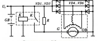
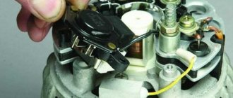
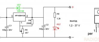
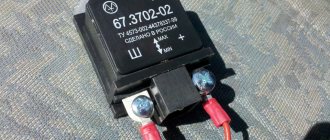
It doesn't matter what type of generator set is used in the car. In any case, it has a regulator in its design. The automatic voltage regulation system allows you to maintain a certain parameter value, regardless of the frequency at which the generator rotor rotates. The figure shows the generator voltage regulator relay, its diagram and appearance.
By analyzing the physics by which a generator set operates, it can be concluded that the output voltage increases as the rotor speed becomes higher. It can also be concluded that voltage regulation is carried out by reducing the current supplied to the rotor winding as the rotation speed increases.
Examination
In order to determine the nature of the breakdown at home, you first need to know how to diagnose the generator.
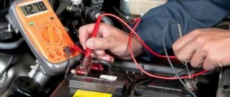
The first stage is carried out without removing the device from the machine. There are several options, but the best quality is a multimeter. True, for this it is best to involve someone you know.
First of all, you need to find out whether the voltage regulator is capable of doing its job. Experts note that most often it is because of this that the generator may not function properly. The problem with it arises due to excessive voltage in the electrical network.
The generator itself is tested like this:
- set the multimeter to volts;
- start the power unit;
- measure the voltage at the battery and at the generator terminals.
Normally, the device will show from 14 to 14.2 volts. After this, you will need to depress the gas pedal - the voltage increase should not exceed half a volt in this case.
An increase in this indicator indicates that the generator’s performance is impaired. Most likely, the voltage relay will need to be replaced.
Alternatively, you can also do this:
- start the engine and let it run for a while;
- press the gas and bring the crankshaft to 3 thousand revolutions;
- turn on the headlights (high beam);
- heated rear window;
- stove fan.
With such a load, the battery voltage should be more than:
- 13.2 volts (generator type – 9402.3701);
- 13,6 (37.3701).
Indicators different from normative ones indicate:
- winding faults;
- failure of the voltage regulator;
- brush breakage.
To exclude the regulator from the list, you need to de-energize all devices except the headlights and measure the voltage again. If the specified node is serviceable, then the indicators will be as follows:
- for 37.3701 – up to 14.6;
- for 9402.3701 – up to 14.7.
This is interesting: Which winter tires are better and how to meet the season fully armed?
What is a generator
Any car generator consists of several parts:
1. A rotor with an excitation winding, around which an electromagnetic field is created during operation.
2. A stator with three windings connected in a star configuration (alternating voltage is removed from them in the range from 12 to 30 Volts).
3. In addition, the design contains a three-phase rectifier consisting of six semiconductor diodes. It is worth noting that the VAZ 2107 generator voltage relay-regulator (injector or carburetor in the injection system) is the same.
But the generator will not be able to operate without a voltage regulation device. The reason for this is the voltage change over a very wide range. Therefore, it is necessary to use an automatic control system. It consists of a comparison device, control, executive, master and special sensor. The main element is the regulatory body. It can be either electrical or mechanical.
Generator connection diagram for VAZ 2107
The VAZ 2107 charging scheme depends on what type of generator is used. To recharge the battery on cars such as VAZ-2107, VAZ-2104, VAZ-2105, which have a carburetor engine, you will need a G-222 type generator or its equivalent with a maximum output current of 55A. In turn, VAZ-2107 cars with an injection engine use a generator 5142.3771 or its prototype, which is called a high-energy generator, with a maximum output current of 80-90A. It is also possible to install more powerful generators with an output current of up to 100A. Absolutely all types of alternating current generators have built-in rectifier units and voltage regulators; they are usually made in the same housing with brushes or are removable and mounted on the housing itself.
The VAZ 2107 charging circuit has minor differences depending on the year of manufacture of the car. The most important difference is the presence or absence of a charge indicator lamp, which is located on the instrument panel, as well as the method of connecting it and the presence or absence of a voltmeter. Such circuits are mainly used on carburetor cars, while on cars with injection engines the circuit does not change, it is identical to those cars that were manufactured previously.
Generator set designations:
- “Plus” of the power rectifier: “+”, V, 30, V+, WAT.
- “Ground”: “-”, D-, 31, B-, M, E, GRD.
- Excitation winding output: Ш, 67, DF, F, EXC, E, FLD.
- Output for connection to the serviceability lamp: D, D+, 61, L, WL, IND.
- Phase output:
Generator operation
When the rotor begins to rotate, some voltage appears at the generator output. And it is supplied to the excitation winding through a control element. It is also worth noting that the generator set output is connected directly to the battery. Therefore, voltage is constantly present on the excitation winding. When the rotor speed increases, the voltage at the generator set output begins to change. A voltage regulator relay from a Valeo generator or any other manufacturer is connected to the generator output.
In this case, the sensor detects the change, sends a signal to a comparing device, which analyzes it, comparing it with a given parameter. Next, the signal goes to the control device, from which it is supplied to the actuator. The regulatory body is able to reduce the value of the current that flows to the rotor winding. As a result, the voltage at the generator set output is reduced. In a similar way, the mentioned parameter is increased in the event of a decrease in rotor speed.
Two-level regulators
A two-level automatic control system consists of a generator, a rectifier element, and a battery. It is based on an electric magnet, its winding is connected to the sensor. The driving devices in these types of mechanisms are very simple. These are ordinary springs. A small lever is used as a comparison device. It is mobile and makes switching. The actuator is the contact group. The control element is a constant resistance. Such a generator voltage regulator relay, the diagram of which is given in the article, is very often used in technology, although it is morally outdated.
Electronic regulator
Two-level mechanical voltage regulators have a big drawback - excessive wear of the elements. For this reason, instead of an electromagnetic relay, semiconductor elements operating in key mode began to be used. The operating principle is similar, only the mechanical elements are replaced by electronic ones. The sensing element is made on a voltage divider, which consists of constant resistors. A zener diode is used as a driving device.
The modern relay-voltage regulator of the VAZ 21099 generator is a more advanced device, reliable and durable. The executive part of the control device operates on transistors. As the voltage at the generator output changes, the electronic switch closes or opens the circuit, and additional resistance is connected if necessary. It is worth noting that two-level regulators are imperfect devices. Instead, it is better to use more modern developments.
Operation of a two-level regulator
When the generator operates, a voltage appears at the output, which is supplied to the winding of the electromagnetic relay. In this case, a magnetic field arises, with its help the lever arm is attracted. The latter is acted upon by a spring, which is used as a comparing device. If the voltage becomes higher than expected, the contacts of the electromagnetic relay open. In this case, a constant resistance is included in the circuit. Less current is supplied to the field winding. The voltage regulator relay for the VAZ 21099 generator and other domestic and imported cars operates on a similar principle. If the voltage at the output decreases, then the contacts are closed, and the current strength changes upward.
Electronic warning lamp relays.
Also, in addition to electromagnetic relays, electronic relays. Of course, these relays are much more reliable. They were widely used in foreign cars produced in the 80s. The principle of these relays is to control the voltage of the on-board network. If the voltage is less than the nominal value, then the control lamp is turned on using an electromagnetic relay or a built-in transistor. On domestic cars, this principle is found on Nivas with a carburetor engine and an imported instrument panel, as well as on other models with imported instrument panels. As a control lamp, such panels used an LED, which was controlled by a unit built into the panel. Such cars were produced in a limited edition.
Three-level regulation system
The quality of regulation of such structures is much higher than that of those previously discussed. Previously, mechanical designs were used, but today non-contact devices are more common. All elements used in this system are the same as those discussed above. But the operating principle is slightly different. First, voltage is applied through a divider to a special circuit in which information is processed. It is possible to install such a generator voltage regulator relay (Ford Sierra can also be equipped with similar equipment) on any car if you know the device and connection diagram.
Here the actual value is compared with the minimum and maximum. If the voltage deviates from the value that is set, then a certain signal appears. It is called a mismatch signal. It is used to regulate the current flowing to the excitation winding. The difference from a two-level system is that there are several additional resistances.
Diode bridge
It is necessary to ring each diode separately in different directions. But normally the signal will sound only once. If a squeak is heard in both cases, the part needs to be replaced. However, in fact, the easiest way is to install a completely new bridge - it is not that expensive.
Modern voltage regulation systems
If the voltage regulator relay for the generator of a Chinese scooter is two-level, then more advanced devices are used on expensive cars. Multilevel control systems can contain 3, 4, 5 or more additional resistances. There are also tracking automatic control systems. In some designs, you can refuse to use additional resistances.
Instead, the frequency of operation of the electronic key increases. It is simply impossible to use circuits with electromagnetic relays in servo control systems. One of the latest developments is a multi-level control system that uses frequency modulation. In such designs, additional resistances are required, which are used to control logic elements.
Voltage regulator relay VAZ 2106 - types of device
The task of this element of the car is to provide automatic continuous modification of the excitation current strength so that the voltage at the generator is always within standard limits when its load and rotation speed change.
On “sixes” there can be two types of regulators:
- electromagnetic;
- electronic contactless.
The first device is outdated; it has not been produced as spare parts for the VAZ 2106 for a long time. You can only find such a relay on old cars, and even then it’s extremely rare. But a contactless electronic regulator can be purchased at any auto store. This device is very popular among motorists, as it does not require any special complex adjustments or critical settings.
If the old electromagnetic relay-regulator fails, it is simply replaced with a new electronic one - both types of devices are completely interchangeable, so the electronic circuit does not need to be changed or modified.
But before you decide to replace the described relay, professionals strongly recommend checking the old device to ensure its performance. Often the problem lies not in it, but in other mechanisms and components of the vehicle.
How to remove the relay regulator
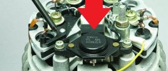
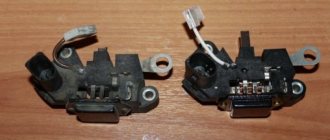
Removing the generator voltage regulator relay (“Lanos” or domestic “nine” is not important) is quite simple. It is worth noting that when replacing the voltage regulator, you only need one tool - a flat-head or Phillips screwdriver. There is no need to remove the generator or the belt and its drive. Most of the devices are located on the back cover of the generator, and are combined into a single unit with a brush mechanism. The most common breakdowns occur in several cases.
Firstly, when completely erasing the graphite brushes. Secondly, in case of breakdown of a semiconductor element. How to check the regulator will be discussed below. When removing, you will need to disconnect the battery. Disconnect the wire that connects the voltage regulator to the generator output. By unscrewing both mounting bolts, you can pull out the device body. But the voltage regulator relay for the VAZ 2101 generator has an outdated design - it is mounted in the engine compartment, separately from the brush assembly.
Replacing the unit
It is not difficult to remove the generator from the classic Zhiguli model. But it is mounted at the bottom of the engine compartment, under the engine, and must be removed from below. This means that you will need an inspection hole or overpass. The preparatory operation consists of placing the car in a pit and removing the engine crankcase protection, if any. It is also necessary to open the hood and remove the negative ground terminal of the battery. Now everything is ready for removal.
The work is performed in the following order. Disconnect the generator of your VAZ 2101 from the vehicle's electrical system. Unscrew the nut securing the positive wires to the generator. Disconnect the brush connector and the diode bridge connector.
Unscrew the nut securing the unit to the adjustment bar a couple of turns. If possible, use a socket head and an extension with a universal joint. Tilt the generator so that the belt sags on the pulleys of the crankshaft, water pump and VAZ 2101 generator. Remove the belt.
Go down into the pit. Using a 19 mm wrench, unscrew the large fastening nut. The bolt that secures the unit is located at the very bottom of the engine compartment and is exposed to wind and water, snow and dirt, so it often sticks. Knock it out with a hammer. Carefully remove the generator from the VAZ 2101.
If repairs are expected, proceed to it. Replacement is planned - mount the generator on your VAZ 2101 in the reverse order. To connect, connect the plugs and tighten the nut securing the wires.
Device check
The relay-regulator of the voltage of the VAZ 2106 generator, “kopecks”, and foreign cars is checked equally. As soon as you remove it, look at the brushes - they should be more than 5 millimeters long. If this parameter is different, the device must be replaced. To carry out diagnostics, you will need a constant voltage source. It would be desirable to be able to change the output characteristic. You can use a battery and a couple of AA batteries as a power source. You also need a lamp, it must run on 12 Volts. You can use a voltmeter instead. Connect the plus from the power supply to the voltage regulator connector.
Accordingly, connect the negative contact to the common plate of the device. Connect a light bulb or voltmeter to the brushes. In this state, voltage should be present between the brushes if 12-13 Volts are supplied to the input. But if you supply more than 15 Volts to the input, there should be no voltage between the brushes. This is a sign that the device is working properly. And it doesn’t matter at all whether the voltage regulator relay of the VAZ 2107 generator or another car is diagnosed. If the control lamp lights up at any voltage value or does not light up at all, it means that there is a malfunction of the unit.
Signs that a check is needed
If the battery on your scooter often runs out, and it is still quite new, this means that there is a problem with the operation of the relay regulator. As practice shows, it burns out quite often. If the device is faulty, the battery stops charging completely and loses its capacity. This means you won’t be able to start the scooter with a button; you’ll have to start it with a kickstarter.
Another characteristic sign of incorrect operation of the device may be the frequent burnout of incandescent light bulbs. They themselves are durable and have a good durability, but are quite sensitive to voltage changes. This happens because the optimal voltage in the scooter network is considered to be 12-13 V. Increasing this value even by 2 V reduces the service life of electronics and components by 2 times.
The greater the deviation from the norm, the greater the likelihood that something will burn out in the scooter. Therefore, when starting the scooter from the starter due to a power surge and a faulty relay, the bulbs usually burn out.
Signs of a malfunctioning regulator are identical for all models of Chinese scooters. They are especially typical for charging relays for scooters of Chinese models with an engine capacity of 50 cc. Therefore, before making a decision to replace something in electronics, testing systems and devices should begin with the relay regulator.
For all models of Chinese scooters, the symptoms of a malfunction of the regulator are identical.
conclusions
In the electrical system of a car, the voltage regulator relay of the Bosch generator (as, indeed, of any other company) plays a very important role. Monitor its condition as often as possible and check for damage and defects. Cases of failure of such a device are not uncommon. In this case, in the best case, the battery will be discharged. And in the worst case, the supply voltage in the on-board network may increase. This will lead to the failure of most electricity consumers. In addition, the generator itself may fail. And its repair will cost a tidy sum, and considering that the battery will fail very quickly, the costs will be astronomical. It is also worth noting that the Bosch generator voltage regulator relay is one of the leaders in sales. It has high reliability and durability, and its characteristics are as stable as possible.
How to check the pH on a VAZ-2110 without removing it
If you find at least one of the listed signs, do not be lazy to check the voltage regulator on your VAZ-2110. This procedure will not take more than 10 minutes. To do this, you will need a voltmeter or multimeter turned on in its mode, as well as an assistant. The verification procedure is as follows:
- We start the car engine and warm it up to operating temperature.
- Without turning off the engine, we connect one voltage probe of the generator, and the second to the “ground” of the device.
- We ask the assistant to turn on the low beam headlights and press the accelerator pedal, keeping the speed at 2000-2500 thousand rpm.
- We measure the voltage with the device.
For the VAZ-2110, the voltage regulator should produce 13.2-14.7 V. This is the norm. If the voltmeter readings differ from those shown, diagnostic measures should be continued.
Remote controller
ATTENTION! A completely simple way to reduce fuel consumption has been found! Don't believe me? An auto mechanic with 15 years of experience also didn’t believe it until he tried it. And now he saves 35,000 rubles a year on gasoline! Read more"
This often happens to drivers. The brushes of the generating device burn out. The regulator is built in along with the brushes. We have to change everything together. And here’s some advice from experts: it’s better to install an external regulator than a built-in one. The models released recently have not been praised very much.
Okay, do you think I’ll install an external one, but how do I connect it? It turns out that there is a convenient scheme that makes it easy to carry out all this modernization.
Some important points:
- do not confuse the chips on the regulator numbered 67 and 15 (the first should be connected to the generating device, and the second should go to the fuses);
This is what the connection diagram looks like
In the lower photo we see a diagram that shows the connection of the already built-in regulator relay.
It is suitable for connecting to “fives”, “sevens”, VAZ 2104, if the PG is installed from a VAZ “kopek”. As you can see, the remote-type regulator relay is connected via two terminals. Pin 15 goes to the fuse.
The second pin 67 is connected to the generator. The wire is connected to the brush chip.
Also, the remote-type relay must be connected to ground - any part of the body.
A relay is nothing more than a switch that serves to close and disconnect individual zones of an electrical circuit that occur at specific electrical values. A machine relay is otherwise called a load voltage switch, and this is 100 percent true. When the power supply unit, fan or starter consumes more current than necessary, the relay trips.
The relay consists of an electric type magnet, an armature and a switch. In this case, the electromagnet is a cable twisted around an inductor with a magnetic rod, and the armature is a special plate that controls the contacts.
As soon as electrical voltage passes through the magnet winding, an electric field is created. A special pusher presses the armature against the core and, thereby, the contacts switch.
Attention. There are two types of relays used on VAZ cars. This is a non-contact relay-regulator and MER (electric). It is the diagram of the last relay that is shown in the picture below.
The non-contact relay or NERR is a fairly new unit that does not require any additional adjustments or regulation. As for the MED, this is an old-style device, the production of which has currently been suspended.
So, the BRN or built-in regulator is a device consisting of a microcircuit, a transistor and a housing with brushes. If the built-in regulator fails, it is replaced with a new one, or an external one is installed.
The external regulator is easy to install if you strictly follow the instructions.
Modernization involves dismantling and disassembling the generating device.
Electric relay device
An automobile charging relay, a photo of which can be found on our Internet portal, contains the following elements:
- Electromagnetic device - consists of a coil with a metal core that exhibits magnetic properties, and a wire of a certain cross-section that plays the role of a winding.
- An anchor element is a product made from a special plate that directs the contacts to the desired action, depending on the impulse received from an electromagnetic type coil.
- Position switch - combines the functions of switching, opening and closing contacts.
When voltage is applied through the electromagnetic winding of the coil, an electric field is created that attracts the armature element to the core, and the pusher, under the influence of the coil current, stirs the armature element, thereby switching the contacts of the “six” charging relay, the price of which is quite reasonable for Russian motorists. The correct connection of the charging relay can be seen in the image below
There are 2 main types of charging regulator relays used on “sixes”. These include:
- Automotive relay-regulator charging VAZ 2106 non-contact type, having the nomenclature number 121.3702. This is a relatively new electronic device used to complete the power equipment of the Six. The main advantage of this device is its complete autoregulation.
- The product under the symbol PP-380 with the same functions is installed on the “six” from the beginning of its release from the assembly line. The part is currently discontinued.
These charging relays are interchangeable, and, which is very convenient, without subsequent modifications and adjustments to the VAZ 2106 charging circuit, which is presented below
The VAZ 2106 charging circuit diagram includes a charging lamp relay (RS-702), which serves to receive signals from an indicator lamp on the instrument panel, which shows whether the charge current is flowing to the windings of the generator device and indicates its functionality. This charging lamp relay is located on the right fender liner in the engine compartment.
To check the functionality of the charging relay regulator of the VAZ 2106, you need to turn on the ignition, start the engine and achieve the required number of revolutions (2500-3000 rpm) of the power plant. Next, you should turn off all automotive electrical consumers (except for the ignition), and measure the potential difference at the output contacts of the product. The voltage at the ends should be 14.2 Volts.
If, when the charging relay is connected correctly, a problem is observed with its functionality, then this device should be repaired. To do this, you must have certain skills in electrical engineering and the ability to use an ampere-voltmeter and other measuring instruments and, possibly, a soldering iron. Otherwise, it is necessary to replace this element of the vehicle's electrical system, which can be purchased at a specialized store of automotive spare parts and components. Such a charging relay has a relatively low price, at least quite comparable with other components of the vehicle’s power supply system.
GU or generator
The generator in any automotive electrical circuit performs the dominant functions. The normal functioning and operation of the machine depends on it. Reliable PG is installed in all foreign cars and models of the domestic automobile industry.
For example, a GU is placed on the “six”, the charge of which satisfies the need for electricity of any standard component. If you do not overload the generating device of the “six”, then the car is capable of driving many, many more kilometers. However, it is important to carry out preventive procedures in a timely manner - monitor the belt tension and the condition of the brushes.
The GU is connected according to the classical scheme. Using the VAZ 2106 generator as an example, let’s consider its functioning. This GU is marked as G-221. It is an AC synchronous electric machine with ELMG excitation. A VB (rectifier) with 6 diodes is built inside the GU.
| 1 | generator rotor winding |
| 2 | generator |
| 3 | generator stator winding |
| 4 | generator rectifier |
| 5 | accumulator battery |
| 6 | ignition switch |
| 7 | battery charge indicator lamp |
| 8 | battery warning light relay |
| 9 | fuse box VAZ -2106 |
| 10 | throttle |
| 11 | temperature compensation resistor |
| 12 | additional resistors |
| 13 | voltage regulator |
A simple and understandable scheme that does not require any subtleties or specific knowledge. On the “six” the PG is located on the engine on the right. It is attached to the tension bar with a nut and to the bracket with its claws.
As you can see, the diagram shows an external regulator. It is marked with the number 13. The generator is indicated with the number 2, the fuse box is indicated with the number 9.
Generator device
The design of a car generator implies the presence of its own rectifier and control circuit. The generating part of the generator, using a stationary winding (stator), generates three-phase alternating current, which is then rectified by a series of six large diodes and the direct current charges the battery. Alternating current is induced by the rotating magnetic field of the winding (around the field winding or rotor). Next, the current is supplied to the electronic circuit through the brushes and slip rings.
Generator structure: 1.Nut. 2. Washer. 3.Pulley 4.Front cover. 5. Distance ring. 6.Rotor. 7.Stator. 8.Back cover. 9.Casing. 10. Gasket. 11.Protective sleeve. 12. Rectifier unit with capacitor. 13.Latch holder with voltage regulator.
The generator is located at the front of the car engine and is started using the crankshaft. The connection diagram and operating principle of a car generator are the same for any car. There are, of course, some differences, but they are usually associated with the quality of the manufactured product, the power and the layout of the components in the motor. All modern cars are equipped with alternating current generator sets, which include not only the generator itself, but also a voltage regulator. The regulator equally distributes the current in the excitation winding, and it is due to this that the power of the generator set itself fluctuates at a time when the voltage at the power output terminals remains unchanged.
The principle of operation of a car generator
Connection diagram for the VAZ 2110-2115 generator
The alternator connection diagram includes the following components:
- Battery.
- Generator.
- Fuse block.
- Ignition.
- Dashboard.
- Rectifier block and additional diodes.
The principle of operation is quite simple: when the ignition is turned on plus through the lock, the ignition goes through the fuse box, light bulb, diode bridge and goes through a resistor to minus. When the light on the dashboard lights up, then the plus goes to the generator (to the excitation winding), then during the process of starting the engine, the pulley begins to rotate, the armature also rotates, due to electromagnetic induction, electromotive force is generated and alternating current appears.
Next, the diode passes plus into the rectifier block through a sine wave into the left arm, and minus into the right arm. Additional diodes on the light bulb cut off the negatives and only positives are obtained, then it goes to the dashboard assembly, and the diode that is there allows only the negative to pass through, as a result the light goes out and the positive then goes through the resistor and goes to the negative.
The principle of operation of a car DC generator can be explained as follows: a small direct current begins to flow through the excitation winding, which is regulated by the control unit and is maintained by it at a level of slightly more than 14 V. Most generators in a car are capable of generating at least 45 amperes. The generator operates at 3000 rpm and above - if you look at the ratio of the size of the fan belts for the pulleys, it will be two or three to one in relation to the engine frequency.
To avoid this, the plates and other parts of the generator rectifier are partially or completely covered with an insulating layer. The heat sinks are combined into a monolithic design of the rectifier unit mainly by mounting plates made of insulating material, reinforced with connecting bars.
Next, let's look at the connection diagram for a car generator using the example of a VAZ-2107 car.
Removing and installing the voltage regulator
Replacing the external voltage regulator VAZ 2101-2106
1) Using the “8” socket, unscrew the two nuts and remove the regulator.
2) Disconnect the two wires.
3) Attach the new regulator to the mudguard and connect the wires: orange to terminal “15”, and gray to terminal “67”.
Voltage regulator relay connection diagram
ATTENTION! Before starting the engine, make sure that the contact between the voltage regulator housing and the vehicle ground is reliable, and that the wires to terminals “15” and “67” are connected correctly.
Scheme and principle of operation
The operation of the stabilizer for all models is almost the same and consists in distributing the current supplied from the generator to stabilize it and further distribute it to consumers.
The operation of the stabilizer is almost the same for all models
The main peripheral consumers of the scooter include:
- battery;
- indicators;
- light bulbs;
- sensors;
- enrichment agent;
- other nodes;
- starting enrichment.
How does the stabilizer work? The main principle of its operation is to act as a transformer, which lowers the voltage to an optimal level acceptable for the operation of electrical appliances, and also stabilizes the network and prevents unexpected power surges.
If the relay malfunctions, the scooter’s devices fail, quickly wear out or burn out.
To avoid these problems and their undesirable consequences, you should know the basics of the correct operation of the electrical circuit and voltage components of the scooter (Figure 1).
Voltage relay pinout diagram and wiring for main scooter models
The pinout of the relay regulator is standard for all models of Chinese-made scooters.
Scooter relay-regulator pinout
The stabilizer has an aluminum body and plastic contacts, each of which has its own wire. Each contact has its own wire color. This makes it convenient to connect the device to the wires if the plastic connector is worn out. The wires must be connected to the contacts according to the electrical diagram (Figure 3).
Electrical diagram for connecting the relay regulator