Instrument panel VAZ-2108
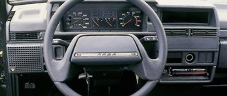
The instrument panel of the basic version of the G8 was popularly nicknamed “low” because of its appearance. It is a large shelf, the surface of which is located below the level of the windshield. Used in the VAZ-2108 until 1997. And then the panel was replaced with a “high” one for cars with index 21083.
On the left half, the instrument panel of the VAZ-2108 rises above it. To the left of the steering wheel there are control handles for the hydraulic leveling of the headlights and the illumination of the instrument panel.
On both sides of the steering column there are combined control levers for electrical appliances. The left one is designed to turn on the turn signals, constant and short-term high beam headlights. The right one controls the windshield and rear window wipers, as well as the washer pump. Also on the right side is the ignition switch and the carburetor choke lever (choke handle).
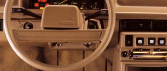
Above the central tunnel are:
- heating system deflectors;
- control buttons for the main electrical equipment: side lights, low beam headlights, hazard warning lights, fog lights, heated rear window.
- heater control unit;
- space for a radio;
- cigarette lighter
The heating control unit includes:
- four-position fan switch;
- 2 handles that control the direction of air flow inside the panel (passenger and driver side);
- heater valve control lever.
On the right half of the VAZ-2108 instrument panel there is a glove box (glove compartment) with lighting inside and a small shelf under it.
Dismantling stages
There is a story among “Kulibin” motorists that only a professional, after dismantling and repairing, can put everything back together. In this case, unnecessary parts will remain and everything will work better than before.
This is the result that those who want to replace the instrument panel themselves strive for. There are no particular difficulties in this process, and since all types of panels for a given brand of car are dismantled almost the same way, let’s look at how to remove the dashboard on a VAZ with a low platform.
- Disconnect the battery.
- Set the wheels straight, disconnect the carburetor choke drive rod, and also disconnect the speedometer from the transmission.
- By pulling towards yourself, remove the three interior heating control knobs, as well as the blower mode switching knob.
- On the passenger seat side, disconnect the shield where the instrument panel trim is located, and remove the lower part of the solid panel block.
- Carefully disconnect all connections that are attached to this element.
- The next important step is to unscrew the four screws securing the stove control panel. This step is often skipped, which can later cause the part to break due to sudden pulling.
- Unscrew the screws that are located directly at the top of the niche.
- Remove the housing covering the niche, compress the spring clips on the sides of the glass, blocking access to the scales. Remove the housing and disconnect the speedometer cable.
- Carefully disconnect all wires and mechanisms suitable for this instrument unit.
- Remove all light knobs.
- Remove the steering wheel and related mechanisms.
- The VAZ torpedo is equipped with an anti-theft system that blocks the steering mechanism. Therefore, you need to insert the ignition key to position “0” to unlock the anti-theft system. Only then can the ignition switch be turned off.
- Disconnect the steering column and remove the pipe along with the lock.
- Remove the handle and unscrew the choke rod guide.
- Unscrew the screws located on the left and right (almost at the door itself) that secure the VAZ dashboard on the sides.
- Unscrew the screws located in the glove compartment, as well as near the gas pedal and on the passenger side.
If everything is done correctly, you can completely remove the control panel.
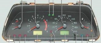
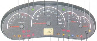
Instrument cluster VAZ-2108
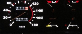
The instrument panel of the VAZ-2108 (low panel) is a combination of the following indicators:
- speedometer;
- mileage counters: daily and total;
- voltmeter, econometer, thermometer;
- fuel level.
In addition to indicators in the instrument cluster there is a set of lamps that indicate:
- insufficient battery charge;
- lack of pressure in the oil supply system;
- carburetor choke position;
- current amount of brake fluid and brake pad wear;
- direction of rotation and activation of the hazard warning lights;
- condition of the parking brake (handbrake);
- state of external lighting (side lights, low beam, high beam or fog lights are on).
Devices 2108 (low panel) allow you to carry out basic diagnostics: brakes, coolant, headlights and taillights. If any element is faulty, its lamp will light up red and the word “STOP” will appear. This indication is advisory in nature and does not prevent the engine from starting.
Pinout of the dashboard of VAZ2113, 2114, 2115
There are 26 contacts on the VAZ-2114 instrument panel, each of which is responsible for the operation of the indicators of this panel. If a plus is supplied to the panel, then each contact displays information about the state in which the car is currently located.
White block (X1)
Red block (X2)
- Housing (weight) - black
- To ambient temperature sensor - cyan-magenta
- Tachometer (low voltage input from ECU) - brown/purple
- Fuse F16 (to terminal 15 of the ignition switch) - orange
- Tachometer (high voltage input from coil) - yellow
- Housing (weight) - black
- To fuse F3 of the mounting block (+battery) - white-purple
- Instrument lighting control - white
- Coolant temperature sensor. - green-white
- Turn signal RIGHT - blue
- To fuse F10 of the mounting block - brown
- Turn signal LEFT - blue-black
- Brake fluid level - pink-blue
- Check Engine Light to ECU Controller - White-Purple
- To the trip computer - brown
- To the ECU controller - pink and black
- Speed sensor - gray and yellow
- To the fuel gauge sensor - orange
- To the fuel gauge sensor - pink
- To the parking brake switch - brown-blue
- Fuse F14 of the mounting block - green-black
- Alternator terminal "D" through fuse panel - brown and white
- Hazard switch
- Oil pressure sensor - blue
- To terminal “50” of the ignition switch - purple
In addition, special indicators and signal sensors are installed on the instrument panel, and the panel itself is controlled by a special electronic unit. Having disassembled the instrument panel, you can see that there are two pads inside it: red and white. And all inputs, outputs and fuses are connected to the plug. If the sensors fail, they will need to be replaced. It is also better to replace damaged or oxidized wires. Indicator lights, like any other, sometimes burn out. Undoubtedly, they need to be replaced with whole ones. Along with them, the lamp sensor often burns out.
VAZ 2114 instrument panel connection diagram
- rear window heating switch;
- rear fog lamp switch;
- switch for headlights and direction indicators;
- mounting block;
- wiper switch;
- fog light switch;
- on-board control system display unit;
- instrument panel harness block to additional harness;
- instrument cluster;
- instrument panel harness connector to the on-board computer harness;
- instrument panel harness connector to the ignition system harness;
- instrument panel harness connector to the side door harness;
- fuse 16 A;
- fuse 16 A;
- ignition switch;
- lighting switch;
- heater electric motor;
- additional resistance of the heater electric motor;
- ignition switch unloading relay;
- rear fog light relay;
- starter relay;
- socket for connecting a portable lamp;
- cigarette lighter;
- instrument panel harness connector to the glove compartment lamp wiring harness;
- illuminator;
- illuminator;
- illuminator;
- heater switch;
- instrument lighting regulator with rheostat;
- brake light switch;
- horn switch;
- hazard switch;
- heater control lamp;
- fuse 16 A;
- seat heating relay;
Another variant of the connector pinout diagram
- checking the brake fluid level indicator. If you apply +, the brake light will light up. You can connect it to the red wire of the ignition switch, then, just like on 2110/2114, the lamp will be checked when the starter is turned on.
- Hazard warning lamp will light up when + is applied.
- high beam lamp, connect to the green-black wire.
- fuel level indicator, connect to the pink-red wire.
- to the speed sensor.
- speed signal output to the on-board computer. If there is one, then take the speed signal from this contact.
- Brake fluid level indicator, connect to the pink-blue wire near the lamp above the cigarette lighter. In the VAZ-2107, the lamp works the other way around: the sensor connects the lamp to ground and it lights up. You will have to either leave the lamp where it is, or in the new device, solder the lamp to + and swap the diodes (in this case, to check the lamp, pin 1 must be connected to ground, for example, to the parking brake lamp), or remove the black wire from the sensor on the tank, and connect instead the orange one from the EPHH unit, or the blue one from the ignition coil, while the diode in the wiring (between the beard and the glove compartment) must be disconnected; if this is not done, there will be a short circuit.
- left turn lamp, connect to the blue-black wire of the steering column switch block.
- Right turn lamp, connect to the blue wire of the steering column switch pad.
- instrument lighting, connect to the white wire.
- ground, connect to the black wire.
- power supply of devices, connect to the orange wire.
- if the device is simple (without microcircuits, etc.), then connect it to the blue-red wire (fuel reserve lamp), if there is a display under the tachometer, then connect it to the temperature sensor (take from a VAZ-2114, one contact to the device, the other to ground, place it either in the passenger compartment or in the engine compartment, but far from the engine and so that the wind does not blow).
- ground, connect to the white-black wire.
- low-voltage tachometer input (from the ECM), connect to the brown-blue wire.
- high-voltage tachometer input (from the coil), connect to the brown-blue wire.
- If there is a display under the speedometer, then connect it to the red and white wire at the brake light switch.
- coolant temperature gauge, connect to the green-white wire.
- outdoor lighting lamp, connect to the yellow wire.
- carburetor choke cover lamp, connect to the gray-orange wire.
- go to the ECM lamp. If the machine is injection, then connect one of the contacts to the orange wire, and the other to the remaining one.
- go to the ECM lamp. If the machine is injection, then connect one of the contacts to the orange wire, and the other to the remaining one.
- power supply of devices, connect to the orange-blue wire.
- handbrake lamp, connect to the brown wire.
- battery charge lamp, connect to the brown-white wire.
- low oil pressure lamp, connect to the gray-blue wire.
Dashboard of a VAZ-21083 car
In the early 90s, the interior of front-wheel drive models was completely redesigned and the main change was a new “high” instrument panel with index 21083. It was unsuccessfully copied from the Volkswagen Golf 2 and was installed in cars 21083, 21093, 21099 until 2002-2003. Compared to the instrument panel of the VAZ-2108, the 21083 was more bulky and angular, and some controls were moved. For example:
- The headlight and hazard warning buttons are located on the edges of the instrument cluster.
- The buttons for heating the rear window and fog lights are located to the left of the steering wheel, next to the hydraulic corrector handle.
Space was also added for the on-board computer and power window switches in the central part of the panel. In cars equipped with an injector, the engine control unit is attached to the back of the shelf under the glove compartment.
Why the instrument panel on the VAZ 2109 carburetor does not work
Best site news
malfunctions and troubleshooting methods for the instrument panel on a VAZ 2108, VAZ 2109, VAZ 21099
Possible malfunctions of control devices, causes of malfunctions and solutions
2. Replace the temperature or fuel level sensor3. Check wires, restore connections
The fuel gauge needle returns to the beginning of the scale when the tank is full
The float travel limiter is installed incorrectly (the resistor winding is running out) Bend the limiter 1-2 mm downwards
The fuel gauge needle moves irregularly and often falls towards
1. Weak contact of the fuel level sensor resistor with the current collector 2. Break in the fuel level sensor resistor winding 1. Bend the fuel level sensor current collector 2. Replace the fuel level sensor
The fuel reserve indicator light is constantly on
1. Short circuit of the sensor wire with ground 2. Short circuit of the flexible tire of the sensor with the fuel intake tube 1. Check and eliminate the short circuit 2. Bend the tire
Any instrument panel warning lights do not work
1. The lamp is burnt out 2. Insufficient pressure of the lamp socket contacts to the printed circuit board 3. The sensor contacts are oxidized 4. The lamp sensor is faulty 5. Break in the wires, oxidation of the wire tips 1. Replace the lamp 2. Bend the lamp socket contacts or replace it 3. Clean the contacts sensor 4. Replace sensor 5. Replace damaged wires, clean tips
Speedometer doesn't work
1. The nuts securing the ends of the flexible shaft of the speedometer drive are not tightened 2. The flexible shaft of the speedometer drive is broken 3. The speedometer mechanism is damaged 1. Check and tighten the nuts
2. Replace the flexible speedometer drive shaft3. Replace the speedometer or instrument panel
Noise from the speedometer drive shaft
1. The shell of the flexible speedometer drive shaft is deformed (dents, kinks, etc.) 2. The flexible speedometer drive shaft is installed with bending radii less than 100 mm 1. Replace the flexible speedometer drive shaft
2. Correct the installation of the flexible speedometer drive shaft
When using site materials, an active link to car-exotic.com is required!
Best site news
Similar news:
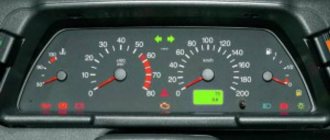
Instrument cluster VAZ-21083
The instruments of the VAZ-2108 (high panel) have been radically changed:
- Added: tachometer, TEST lamps, Check engine, battery charging, driver and passenger seat belts.
- Removed: voltmeter, econometer; indicators for heated rear window, fog lights and hazard warning lights. The last 3 have been placed to the right of the buttons that enable them.
The structure of the dashboard is as follows:
- on the left is the speedometer;
- in the center at the top edge there is a diagnostic unit;
- in the center of the combination there is a coolant thermometer and a fuel level scale;
- on the right – tachometer;
- all indicator lamps are located along the lower edge of the instrument panel in the form of rectangles.
Having once read an article on one of the sites about replacing the instrument cluster (hereinafter referred to as KP) of a VAZ 21083 with a “high” panel with a combination with 2110, I decided to do the same in the version with a “low” panel. I also found a description of the alteration itself. At first glance, everything seemed as simple as shelling pears, however, having taken it seriously, it turned out that the 2115 dlski does not fit into the visor of the standard instrument panel, although it coincides exactly in dimensions with the 2110.
Minuses:
- no suitable visor! You either need to do it yourself, or buy a decorative plastic overlay for the “low” panel and adjust everything to it, as I did;
- you need to cut the front panel itself in order to “recess” the gearbox into it and put the trim on top, because the cover was intended for the standard 2108 gearbox, it also needs to be cut and bent, and fiddling with plastic is quite a troublesome task.
- There will no longer be such useful instruments as a voltmeter and an econometer.
Pros:
- built-in clock with LCD indicator;
- built-in LCD outdoor temperature indicator with ice warning function;
- well, a very nice backlight that cannot be compared with the standard 2108,
- there is a tachometer, and the movement of all the needles is smooth, without jerking (thanks to the stepper motors used)
By the way, in addition to the 2115 gearbox itself, you also need to acquire a speed sensor. There are three varieties: 1. GM (with an American standard round plug), 2. domestic with a plastic shaft, 3. domestic with a metal shaft.
You should take only the third type, because the plastic shaft softens from the heat of the gearbox and flies very quickly, and for GM it is difficult (and most importantly expensive) to buy a mating part of the connector. Do not forget to look for the inscription “6 imp/revolution”, because The sensor for the trip computer looks exactly the same, but gives 10 pulses per revolution. If you want to implement the function of measuring the outside air temperature, you also need a temperature sensor. I recommend the VDO sensor, it has the smallest error. There must be a block with wires with it!
Step one: redo the electrical
Using a small screwdriver, remove the terminals from the blocks leading to the dashboard and shuffle them according to the following table.
| Combination 2108 | The wire | Chain | Combination 2115 | ||
| Block | Terminal | Block | Terminal | ||
| red | 9 | TO | Counter. side light lamp | white | 6 |
| red | 1 | AF | Counter. high beam lamp | red | 11 |
| white | 7 | GP | Counter. fuel level lamp | — | — |
| red | 6 | RG | Counter. brake level lamp liquids* | red | 7 |
| red | 7 | KG | Counter. parking brake lamp | white | 11 |
| red | 13 | KB | Counter. battery charge lamp | white | 12 |
| red | 5 | SG | Counter. oil pressure lamp | white | 13 |
| red | 11 | GB | Counter. emergency lamp alarm | red | 12 |
| red | 12 | JV | Counter. choke opening lamp | white | 7 |
| red | 4 | GP | Counter. turn signal lamp | — | — |
| ** | ** | MS | - // - left | red | 5 |
| ** | ** | G | - // - right | red | 6 |
| red | 2 | Salary | Counter. glass heating lamp | *** | *** |
| red | 8 | VERY | Counter. fog lamp Sveta | *** | *** |
| white | 4 | B | Instrument lighting**** | red | 4 |
| ***** | OZ | Tachometer input high voltage | white | 3 | |
| ***** | WITH | Speed sensor | red | 9 | |
| white | 2 | ZB | Coolant temperature sensor | white | 5 |
| white | 13 | RP | Fuel gauge input | red | 10 |
| white | 12 | ABOUT | +12V | white | 10 |
| white | 9 | OG | +12V | red | 2 |
| white | 8 | BW | Ground, input 2 temperature sensors | red | 3 |
| red | 10 | H | Weight | white | 1 |
| white | 5 | H | |||
| — | — | — | temperature sensor input 1 | red | 1 |
| — | — | — | const 12 V (from terminal 30 of the ignition switch) | white | 4 |
Notes *- it is necessary to connect +12V to the brake fluid level sensor instead of ground (black wire), for example, from pin 4 (blue-red wire) of the switch or from pin 4 (also blue-red) of the EPHH control unit **- diverted from the corresponding terminal of the hazard warning switch in the console ***- The wire is carefully released from the harness and inserted back into the console, where it is connected to the corresponding warning lamp in the switch housing.
Or it is carefully wrapped with electrical tape, and the wiring from the switch itself is routed to the indicator lamp. For more details, see below **** - in order for the instrument lighting to turn on when the ignition is turned on, I have a “plus” applied to the “positive” contact of the instrument illumination brightness adjustment resistor from terminal 15/2 of the ignition switch, the old contact is insulated. Next, a ***** harness of four wires is knitted - gray, blue and purple, black and orange-green. Black (ground) goes from terminal 3 of the speed sensor connector to terminal 3 of the red combination block. Blue with purple (+12V) - from terminal 15/2 of the ignition switch to terminal 1 of the speed sensor. Gray (speed sensor output) - from terminal 2 of the sensor to terminal 9 of the red combination block. And finally, the orange/green goes from the ignition coil “K” terminal to terminal 3 of the white combination block. The harness is passed in place of the speedometer cable and is sealed with a rubber passage plug. The econometer tube is unscrewed from the manifold along with the fitting and the hole is plugged with a copper bolt.
Step two: implanting the dashboard into the panel
Having made sure that it wouldn’t fit into the window from the old gearbox, I had to take a hacksaw and slowly expand the window on the right and left. It was immediately discovered that under the layer of polyurethane foam that covered the panel, there was also a sheet of metal, which probably should give the panel rigidity. Carefully expanding the panel window, we leave small “ears” made of this metal so that later, bending them as required, drilling holes in them and securing the gearbox with self-tapping screws through the side holes. I expanded it like this: I used a hacksaw blade to make small horizontal slits in the corners of the panel window and several additional slits, not forgetting about the lugs for future fastening. Then, with the effort of his hands, he tried to bend the resulting fragments down. I broke out the excess. The window also had to be expanded from above to ensure an acceptable tilt of the gearbox. We don't touch anything at the bottom. I also had to cut off the upper lugs of the gearbox, which interfered with the normal installation of the lining.
Step three: installing decorative trim
You need to recess the gearbox into the panel so that the cover can sit on top of it normally. I strongly do not recommend using covers made of fiberglass. They cannot be bent using heat. Fiberglass does not melt even in a fire, and it is difficult to cut. We cut out the upper part of the lining according to the shape of the gearbox glass, the lower and side parts should be brought out under heating so that with subsequent trimming the shape of the gearbox glass is obtained. Under heating, we try to move them as far as possible in opposite directions in order to expand the window of the lining. The plastic was heated using a Chinese gas burner (a tiny blowtorch), which provided good spot(!) heating. We do not recommend heating over a gas stove, because... plas. Having stopped heating, we immediately try to “bend” the walls inward with our fingers, thereby expanding the window. Any excess that interferes with fitting is immediately trimmed with a blade. The situation was worse with the lower left and right corners. They are important because lamps indicating external lighting and suction could be hidden behind them. I warmed more of the side of the corner, and not the bottom, because otherwise the lower part of the lining will “float”. There were some minor mistakes; I tried to correct the inaccuracies in the reverse order. Next we paint the entire trim with matte black paint. To hide the defects in trimming the trim, I placed a seal from the rear light of a VAZ 2105/2107 around the perimeter of the cut window. The trim is attached with self-tapping screws from the ends of the panel, and the front part of the trim is secured with double-sided tape. As practice shows, this is enough. You can also screw the front part with self-tapping screws and paint their heads black, but, to put it mildly, this will not add any special aesthetics.
I indicate the operation of fog lights, flashlights and rear window heating in the following way: we replace all these buttons with similar ones, but with internal illumination, and not with light bulbs, with LEDs of the required size and color with a 2 kOhm resistor, and remove the green filter. We do the same with the outdoor lighting switch, replacing the light bulb with an LED. Small printed circuit boards with soldered current-limiting resistors and red LEDs are installed in the places provided in the console next to the buttons so that the light from the desired LED falls directly on the light guide ('eye') of the desired button. The switching wires are connected through the connector to the contacts in the block of the desired button, to which + 12V is supplied after switching on.
We will not change the hazard warning button, but simply disassemble it and insert a red LED into it (with a resistor, of course). Don’t forget to display the contacts to which power will be supplied (see how this is done in the backlit button). Next, you need to connect all the lights in parallel with the lights on the outdoor lighting switch, while observing the polarity. Otherwise, the LEDs simply will not light up.
Step four: installing an outside temperature sensor
Information about the outside temperature is very relevant, especially in the off-season at the first frost. For the most part, it was for the sake of this option that the choice fell on KP 2115, and not from 2110. We install the sensor so as to isolate it from direct sunlight, heat from the engine compartment, from heated asphalt and ensure that it is blown with oncoming air. In the “eighth” bumper, this place is in the lower part on the right side of the cutouts for cooling the radiator. To mount the sensor, you need a bracket made of sheet metal 0.8...1 mm thick, sketch below.
We bring the wires from the sensor into the engine compartment and lay them along the headlight harness, then we lead them into the interior to the instrument cluster, where they are connected to contacts 3 and 1 of the red block. Another option: since there is only one wire “ground”, you don’t have to pull it across half the car, but screw it in any convenient place in the engine compartment. If all connections are made correctly, then when the ignition is turned on, the left display will show the outside temperature value, otherwise - “- 40 C”.
We count expenses
- Instrument cluster VDO 2115 — 2400 rub.
- Speed sensor - 160 rub.
- Temperature sensor - 150 rub.
- Decorative overlay 2108 — 600 rub.
- Buttons with internal backlight - 3x35=115 RUR.
- Wires, connectors and pads for buttons - 50 rubles. Plus the cost of the work, if you don’t do something with your own hands (I got 540 rubles)…
Is it worth paying that kind of money for the interior lighting of the instrument cluster? There is, however, a cheaper option: do not install the trim, but try to make the visor yourself, and so that its height and mounting fastenings coincide with the standard ones.
Instrument panel VAZ-2114 (European panel)
This part was installed only in the VAZ 21099-40 of the last years of production (2000-2002) and the second generation of Lada-Samara: 2113, 2114, 2115. But thanks to the identical interior dimensions and the 2111 engine, this panel can be easily installed in fuel-injected V8s " and "nines".
Panel 2114 has a smoother and more rounded shape compared to 21083. Lighting control buttons are located above the compartment for the on-board computer to the right of the driver. An additional glove compartment compartment has been added: it opens from inside the main one.
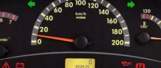
Instrument cluster VAZ-2114
It is equipped with an electronic speedometer, tachometer, fuel level and coolant temperature scales. The express diagnostic unit in the instrument panel 2114 has been simplified: instead of it, there are indicators of the health of the headlight bulbs and brake pads, as well as the “Check Engine” icon. The remaining warning lamps (oil pressure, battery charge, direction of rotation, side lights, low beam, high beam) are located in the lower corners of the device.
Instrument panels VAZ VDO (LED)
You can install a more beautiful and convenient panel with LED indicators, the so-called VDO panel. Here VDO is the panel manufacturer.
| Connecting VDO on a Kalina car | ||
| 1 | Pink-white | To electric power steering |
| 2 | Blue and white | To the hazard warning indicator |
| 3 | Gray-blue | To emergency oil pressure sensor |
| 4 | Brown blue | To the parking brake switch |
| 5 | Yellow-blue | To the immobilizer control unit |
| 6 | Black | To the airbag control unit |
| 7 | Yellow | To the outside light switch |
| 8 | Blue | To the right turn signal switch |
| 9 | Blue with black | To left turn signal switch |
| 10 | White-blue | TO ECU |
| 11 | . | To brake pad wear sensor |
| 12 | . | To seat belt sensor |
| 13 | Black | To the traction control control unit |
| 14 | Red-blue | “RESET” key on the steering column switch |
| 15 | Pink-blue | To brake fluid level sensor |
| 16 | Black | To ABS |
| 17 | Green | To the high beam switch |
| 18 | White | To the instrument cluster light control |
| 19 | Brown | Panel weight |
| 20 | White-red | Terminal “30” |
| 21 | Orange | Terminal “15” |
| 22 | Yellow-red | To fuel flow sensor |
| 23 | Orange-white | MK key “forward” |
| 24 | White black | MK key “back” |
| 25 | Black and white | Outside temperature sensor (-) |
| 26 | Yellow-green | Outside temperature sensor (+) |
| 27 | Pink | Fuel level sensor |
| 28 | Grey | Speed sensor |
| 29 | Green-white | Coolant temperature sensor |
| 30 | Brown-red | Tachometer (low voltage) |
| 31 | . | Official. Panel diagnostics. |
| 32 | Brown-white | Terminal “L” of the generator relay regulator |
Basic faults
Like any other technical device, the VAZ-2108 instrument panel may break down or display information incorrectly. This happens for 3 reasons:
- The lamp or scale has failed.
- The electrical circuit between the indicator and the signal source is damaged: the tracks in the instrument cluster board are burned out, the wire/cable of the mechanical speedometer is broken, poor contact at the terminal connections due to dirt or oxidation, the fuse has melted.
- The signal source is damaged. For example, the float in the gas tank is stuck in the upper position. Then the fuel level scale will show that there is enough fuel.
To find out on your own why the panel instruments in the VAZ-2108 do not work, you will need a multimeter and repair and operating instructions. It contains instructions for checking each element of the circuit
The instrument panel on the VAZ 2109 does not light up: do-it-yourself repairs, popular faults
- Types of panels
- Why doesn't it light up?
- Popular faults
When the instrument panel on a VAZ 2109 does not light up, this is one of the common malfunctions of this unit. To fix a problem, you first have to find the cause of its occurrence.
Tidying up nine
Types of panels
Instrument panels on the VAZ 2109 are of at least three types:
- Low panel;
- High panel;
- Electronic panel on nines with Europanel.
Europanel
On versions with a low panel, failure of the entire panel is extremely rare. This is due to the fact that here the speedometer and econometer are equipped with mechanical drives. Therefore, it is unlikely that they will fail along with the electrical component.
Dashboards with a high panel do not have an econometer, but the speedometer is also based on a mechanical cable drive.
Why doesn't it light up?
If suddenly electrical appliances and indicator lamps on the dashboard stop working, certain actions must be taken.
- First, remove the cover of the mounting block and make sure that the fuse is intact. The fuse markings are located on the inner surface of the cover. You should look for fuse F16 or F5, depending on the year of manufacture of your VAZ 2109.
- If the fuse is intact, be sure to check whether the contacts of the fuse you are looking for have not oxidized. It is not uncommon for shields to fail due to broken contact.
If none of the above actions yielded results, you will have to be disappointed. After all, now you need to remove the dashboard and check the condition of the wiring, contacts, and negative connections. Here it is better to trust a professional electrician or set aside a whole day to troubleshoot problems yourself. There is no need to rush here.
Where did the backlight go?
Popular faults
If we talk about the dashboard of VAZ 2109 cars, then they are characterized by certain problems. We will tell you about them, and also tell you how to act correctly in a given situation.
Gasoline level and temperature indicator does not work
In most percent of cases, this situation occurs due to breakdown of devices, sensors of these devices, or an open circuit of the power supply. Therefore, first check the circuit for continuity, make sure that the fuses have not blown. If this is not the case, check whether the gas level and temperature sensors are working. Only if none of the actions allowed you to get rid of the breakdown, you can begin to replace the devices themselves. No options, the problem lies in them
When the fuel tank is full, the arrow points to zero
If you have worked on the fuel level sensor, the fault most likely lies with you. When manipulating this device, the float limiter is often knocked down. Either the limiter is installed incorrectly or adjusted, causing the resistor winding to end. To resolve the problem, remove the sensor and then adjust the limiter again
The fuel gauge needle regularly jumps and ends up at zero
Here, most likely, the resistor has weak contact with the current collector. Another possible option is that there is a break in the resistor. To resolve this situation, we recommend replacing the hot level sensor with a new measuring device
The fuel level lamp is constantly on
If this lamp is constantly on, there is probably a short circuit in the fuel level sensor supply wiring to ground. Another option is that the sensor’s flexible bus is shorted to the fuel intake pipe. You will have to disassemble the device to align the bus and get rid of the resulting short circuit
Dashboard upgrade
Some car enthusiasts do not like the gray serial instrument panel of the VAZ-2108. Therefore, they strive to make it better and more unique. Many tuning methods have been invented: simple and cheap, expensive and complex.
Method No. 1. Repaint removable panel elements using spray paint: instrument cluster surrounds, heating deflectors, glove compartment lid.
Method No. 2. Cover the front part of the dashboard with stickers. It is not recommended to stick them on the top of the panel, as the stickers are glossy and reflect in the windshield. This makes it difficult to keep your eyes on the road.
Method No. 3. Install an overlay on the instrument panel of the VAZ-2108. Plastic overlays for the dashboard are available for sale, imitating wood or export equipment of the car. It is also possible to install a Euro panel with minor modifications.
Method No. 4. Installing a tablet computer in the central part of the panel instead of the on-board computer and radio. It will add the function of a GPS navigator and multimedia center to the car.
Dashboard modification options
The VAZ 2108 dashboard trim will help to radically change the interior decoration. You can choose any modification that suits your requirements and wishes. You can transform the interior by installing leather elements with inserts of bright colors instead of boring ones. Quite popular is a panel overlay that allows you to cover the “native” factory background images.
A car with such an insert will resemble a racing car, and you will need to spend a minimal amount of money. There are quite a few similar options for transforming the interior: from laconic snow-white inserts to bright and colorful ones, allowing the car to radically transform.
Drivers who spend a lot of time behind the wheel of their vehicle decide to change the entire VAZ 2108 dashboard or at least some part of it. A simple change of a light filter from green to another - blue, purple or yellow - adds uniqueness and enlivens the interior.
The VAZ dashboard trim and instrument dials, in which the standard font is modified, add newness to the long-familiar elements of the car. The trim on the VAZ dashboard may differ in appearance, and the instrument scales may have different divisions, for example, not 2-3-4, but 2-2.5-3-3.5-4. It is impossible to significantly change or move the location of the dials due to the design of the car, but modifications for stylization are possible.
The overlay on the instrument scale must be replaced with special care, since the probability of breaking thin arrows or knocking down the zero marks of indicators is very high. And it is very difficult to correct this situation, since arrows are rarely sold separately; they can only be found at disassembly. At the same time, they may differ from the factory ones, which cannot but be striking.
The neon trim on the VAZ dashboard looks stylish. In the evening and at night, it gives the feeling of participating in a race in the famous movie “Fast and Furious”. It seems that you just need to press the gas pedal and the accelerator will turn on, which will take you far forward in a matter of seconds. The design of the low panel of the VAZ 2108 does not provide for:
- minimum brake fluid level indicator unit;
- block thickness control unit;
- presence of lamp health indicator and many other functions.
Despite this, the popularity of cars from early years equipped with such an instrument panel does not decrease. Sometimes it’s even the other way around: the demand for a VAZ 2108 dashboard equipped with the first instrument panels is higher for modern cars that their owners are going to convert. A wide shelf, powerful air exchange, or simply a pursuit of retro elevate these instrument panels to the top of the popularity ratings.
Tuning the low panel of a VAZ is no less popular. In this case, there are no limits to the designer’s imagination. The factory location of the buttons and the niche for the car radio allow you to modify and build in, for example, a TV for a car, or change the location and functionality of the buttons depending on your wishes or needs.
Recently, the installation of a rear camera has been gaining popularity, which significantly increases the maneuverability of the car. Any dashboard allows you to build a screen for such a camera, but sometimes it is necessary to additionally connect some functions to free buttons. Manufacturers thought through the VAZ 2108 dashboard taking into account the wishes of not only the driver, but also the passengers. This explains the convenient location of the buttons, accessible exclusively to the driver in order to avoid emergency situations.
Peculiarities
Most of all, “chisels” liked the “low” panel due to one significant difference from the “high” one - the well-designed arrangement of air ducts. In 21083, the air forced by the fan from the heater core is lost somewhere inside it. As a result, the interior does not warm up well.
The second feature is the low quality of plastic and poor fit to body parts. At the slightest vibration or pressure, it begins to creak unpleasantly. And when driving on uneven roads, the noise from it is similar to a baby rattle.
Instrument panels with indexes 2108 and 21083 were installed on the first generation of front-wheel drive models; in addition to the cuts, they differ from each other only in the location of the equipment control buttons and differently combined control devices.