The main symbols that are found on the dashboard of absolutely any car of the VAZ family are: speedometer, fuel gauge, tachometer and sensors to indicate engine temperature.
Pinout of the dashboard of VAZ2105, 2106, 2107
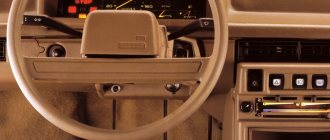
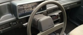
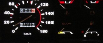
Old panel (with oil pressure gauge)
In addition to the presence of an oil pressure indicator, it is worth noting that this instrument panel does not have an air damper indicator lamp (choke), and the emergency oil pressure lamp is located next to the pressure indicator. Because of this, it contains lamps for low brake fluid levels and fog lamps.
White 6-terminal block X1:
- Gasoline level sensor
- Turn signal indicator lamp
- Battery charge sensor (voltmeter -)
- Gasoline level warning lamp
- Overall plus (+)
- Battery charge sensor (voltmeter +)
White 8 terminal block X2:
- Fog lamp warning lamp
- High beam warning lamp
- Dimensions indicator lamp
- Empty
- Battery charge indicator lamp
- Brake fluid level warning lamp
- Empty
- Parking brake warning lamp
Orange 6-terminal block X3:
- General minus (-)
- Tachometer VAZ
- Instrument lighting
- Oil pressure sensor
- Oil pressure warning lamp
- Coolant temperature sensor
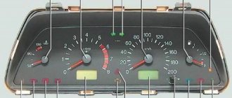
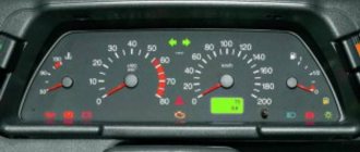
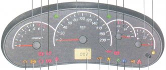
New instrument panel (with econometer)
Here, everything is the other way around - there is no oil pressure indicator (instead there is an econometer), instead of a brake fluid level lamp there is a suction lamp (or an engine management system lamp on injectors), and instead of a fog lamp lamp there is an oil pressure lamp.
White 6-terminal block X1:
- Gasoline level sensor
- Turn signal indicator lamp
- Battery charge sensor (voltmeter -)
- Gasoline level warning lamp
- Overall plus (+)
- Battery charge sensor (voltmeter +)
White 8 terminal block X2:
- Dimensions indicator lamp
- High beam warning lamp
- Oil pressure warning lamp
- Empty, but there is a terminal in the wiring that goes to the brake fluid level sensor
- Battery charge indicator lamp
- Indicator lamp for the air damper (choke) or engine control unit for injectors
- Empty
- Parking brake warning lamp (handbrake)
Orange 6-terminal block X3:
- General minus (-)
- Tachometer (if this contact is empty, then the tachometer is on pin #4)
- Instrument lighting
- Empty, and if not empty - to the tachometer
- Empty
- Coolant temperature sensor
Second connection diagram option
Tuning ideas
There are several tuning options for the dashboard of VAZ cars:
- Installation of a new, modernized dashboard. The range of such devices on the modern market is quite large - consumers are offered many different options for control panels, differing in price and characteristics. As a rule, these are digital devices. The difficulty of this method is that the car owner will have to redo the connectors for connecting the dashboard, and it is also possible that changes will have to be made to the firmware of the control unit.
- Using overlays. One of the most popular and simple types of tuning. In this case, the overlays are mounted on top of the existing instrument scale - instead of the standard scales of the speedometer, tachometer, temperature sensor, gasoline level, etc. Installing the trim involves dismantling the tidy, as well as removing the arrows from the scale. You can purchase such overlays without any problems on the Internet, and if necessary, you can even download them from the Internet.
- Using LEDs. This option is one of the simplest in terms of execution. Its essence lies in removing factory lamps and installing brighter and more beautiful LED light sources instead. Such a simple upgrade will significantly improve the appearance of the control panel, as well as increase its illumination. But you need to understand that there should be enough light, since bright tidy can distract the attention of the motorist. There should be no problems with replacing lamps; they are simply dismantled and new ones are installed in their place. But if you decide to use an LED strip, then you need to take into account that it will have to be soldered to the board, in this case you need to be more careful and attentive.
- Shield trim. This type of tuning can be classified as external, since it will only affect the appearance of the instrument shell. Its implementation is relevant if the shield is worn out or has damage.
Loading …
Pinout of the dashboard VAZ2108, 2109, 21099
Connection diagram of the instrument cluster before 1996.
1 – relay-interrupter for the parking brake warning lamp; 2 – tachometer with voltage stabilizer; 3 – instrument cluster lighting lamp; 4 – temperature indicator; 5 – BSK control unit; 6 – fuel level indicator; 7 – resistor 50 Ohm, 5 W; 8 – control lamp “CHECK ENGINE” for the toxicity reduction system; 9 – control lamp for high beam headlights; 10 – side light indicator lamp; 11 – backup warning lamp; 12 – warning lamp for unfastened seat belts; 13 – control lamp for left direction indicators; 14 – resistor 470 Ohm, 0.25 W; 15 – electronic voltmeter; 16 – control lamp for right direction indicators; 17 – warning lamp for emergency oil pressure; 18 – fuel reserve warning lamp; 19 – control lamp for the carburetor air damper; 20 – indicator lamp “CHECK ENGINE” for the fuel injection system; 21 – parking brake warning lamp.
Instrument cluster wiring diagram after 1996
1 – tachometer; 2 – instrument cluster lighting lamp; 3 – temperature indicator; 4 – BSK control unit; 5 – fuel level indicator; 6 – control lamp “CHECK ENGINE” for the toxicity reduction system; 7 – control lamp for high beam headlights; 8 – side light indicator lamp; 9 – backup warning lamp; 10 – warning lamp for unfastened seat belts; 11 – control lamp for left direction indicators; 12 – battery charge indicator lamp; 13 – control lamp for right direction indicators; 14 – warning lamp for emergency oil pressure; 15 – fuel reserve warning lamp; 16 – control lamp for the carburetor air damper; 17 – indicator lamp “CHECK ENGINE” for the fuel injection system; 18 – parking brake warning lamp; B1 – resistor 91 kOhm; B2 – resistor 50 Ohm, 5 W.
Pinout of the dashboard of VAZ2110, 2111, 2112
- fuel reserve warning lamp;
- dashboard lighting lamps;
- right repeater indicator lamp;
- left repeater indicator lamp;
- VAZ plug block;
- coolant temperature sensor;
- indicator lamp for external lighting;
- carburetor air damper warning lamp;
- oil pressure warning lamp;
- handbrake indicator lamp;
- battery charge indicator lamp;
- VAZ tachometer;
- indicator light “CHECK ENGINE”;
- speedometer dashboard;
- brake fluid level warning lamp;
- hazard warning lamp;
- high beam indicator lamp;
- fuel level indicator.
| White block (X1) | Red block (X2) | ||
| 1 | Housing (weight) | 1 | To terminal “W” of the fuel level indicator sensor |
| 2 | Tachometer (low voltage input from ECU) | 2 | Fuse F19 + 12V power supply |
| 3 | Tachometer (high voltage input from coil) | 3 | Housing (weight) |
| 4 | Const +12V from battery (via 6th fuse) | 4 | Instrument lighting switch |
| 5 | Coolant temperature sensor. | 5 | Turn signal RIGHT |
| 6 | Fuse F1 (side light) | 6 | Turn signal LEFT |
| 7 | Throttle valve (“choke”) | 7 | Brake fluid level |
| 8 | Check Engine Light | 8 | To the trip computer |
| 9 | Fuse F19 + 12V power supply | 9 | Speed sensor |
| 10 | Fuse F19 + 12V power supply | 10 | Terminal “T” fuel gauge |
| 11 | Parking brake, terminal “VK” | 11 | Fuse F3 (high beam) |
| 12 | Generator output “D” | 12 | Hazard switch |
| 13 | Oil pressure sensor | 13 | To terminal “50” of the ignition switch |
Pinout of the dashboard of VAZ2113, 2114, 2115
There are 26 contacts on the VAZ-2114 instrument panel, each of which is responsible for the operation of the indicators of this panel. If a plus is supplied to the panel, then each contact displays information about the state in which the car is currently located.
White block (X1)
Red block (X2)
- Housing (weight) - black
- To ambient temperature sensor - cyan-magenta
- Tachometer (low voltage input from ECU) - brown/purple
- Fuse F16 (to terminal 15 of the ignition switch) - orange
- Tachometer (high voltage input from coil) - yellow
- Housing (weight) - black
- To fuse F3 of the mounting block (+battery) - white-purple
- Instrument lighting control - white
- Coolant temperature sensor. - green-white
- Turn signal RIGHT - blue
- To fuse F10 of the mounting block - brown
- Turn signal LEFT - blue-black
- Brake fluid level - pink-blue
- Check Engine Light to ECU Controller - White-Purple
- To the trip computer - brown
- To the ECU controller - pink and black
- Speed sensor - gray and yellow
- To the fuel gauge sensor - orange
- To the fuel gauge sensor - pink
- To the parking brake switch - brown-blue
- Fuse F14 of the mounting block - green-black
- Alternator terminal "D" through fuse panel - brown and white
- Hazard switch
- Oil pressure sensor - blue
- To terminal “50” of the ignition switch - purple
In addition, special indicators and signal sensors are installed on the instrument panel, and the panel itself is controlled by a special electronic unit. Having disassembled the instrument panel, you can see that there are two pads inside it: red and white. And all inputs, outputs and fuses are connected to the plug. If the sensors fail, they will need to be replaced. It is also better to replace damaged or oxidized wires. Indicator lights, like any other, sometimes burn out. Undoubtedly, they need to be replaced with whole ones. Along with them, the lamp sensor often burns out.
VAZ 2114 instrument panel connection diagram
- rear window heating switch;
- rear fog lamp switch;
- switch for headlights and direction indicators;
- mounting block;
- wiper switch;
- fog light switch;
- on-board control system display unit;
- instrument panel harness block to additional harness;
- instrument cluster;
- instrument panel harness connector to the on-board computer harness;
- instrument panel harness connector to the ignition system harness;
- instrument panel harness connector to the side door harness;
- fuse 16 A;
- fuse 16 A;
- ignition switch;
- lighting switch;
- heater electric motor;
- additional resistance of the heater electric motor;
- ignition switch unloading relay;
- rear fog light relay;
- starter relay;
- socket for connecting a portable lamp;
- cigarette lighter;
- instrument panel harness connector to the glove compartment lamp wiring harness;
- illuminator;
- illuminator;
- illuminator;
- heater switch;
- instrument lighting regulator with rheostat;
- brake light switch;
- horn switch;
- hazard switch;
- heater control lamp;
- fuse 16 A;
- seat heating relay;
Useful: Pinout of contacts for car engine ECU connectors
Another variant of the connector pinout diagram
- checking the brake fluid level indicator. If you apply +, the brake light will light up. You can connect it to the red wire of the ignition switch, then, just like on 2110/2114, the lamp will be checked when the starter is turned on.
- Hazard warning lamp will light up when + is applied.
- high beam lamp, connect to the green-black wire.
- fuel level indicator, connect to the pink-red wire.
- to the speed sensor.
- speed signal output to the on-board computer. If there is one, then take the speed signal from this contact.
- Brake fluid level indicator, connect to the pink-blue wire near the lamp above the cigarette lighter. In the VAZ-2107, the lamp works the other way around: the sensor connects the lamp to ground and it lights up. You will have to either leave the lamp where it is, or in the new device, solder the lamp to + and swap the diodes (in this case, to check the lamp, pin 1 must be connected to ground, for example, to the parking brake lamp), or remove the black wire from the sensor on the tank, and connect instead the orange one from the EPHH unit, or the blue one from the ignition coil, while the diode in the wiring (between the beard and the glove compartment) must be disconnected; if this is not done, there will be a short circuit.
- left turn lamp, connect to the blue-black wire of the steering column switch block.
- Right turn lamp, connect to the blue wire of the steering column switch pad.
- instrument lighting, connect to the white wire.
- ground, connect to the black wire.
- power supply of devices, connect to the orange wire.
- if the device is simple (without microcircuits, etc.), then connect it to the blue-red wire (fuel reserve lamp), if there is a display under the tachometer, then connect it to the temperature sensor (take from a VAZ-2114, one contact to the device, the other to ground, place it either in the passenger compartment or in the engine compartment, but far from the engine and so that the wind does not blow).
- ground, connect to the white-black wire.
- low-voltage tachometer input (from the ECM), connect to the brown-blue wire.
- high-voltage tachometer input (from the coil), connect to the brown-blue wire.
- If there is a display under the speedometer, then connect it to the red and white wire at the brake light switch.
- coolant temperature gauge, connect to the green-white wire.
- outdoor lighting lamp, connect to the yellow wire.
- carburetor choke cover lamp, connect to the gray-orange wire.
- go to the ECM lamp. If the machine is injection, then connect one of the contacts to the orange wire, and the other to the remaining one.
- go to the ECM lamp. If the machine is injection, then connect one of the contacts to the orange wire, and the other to the remaining one.
- power supply of devices, connect to the orange-blue wire.
- handbrake lamp, connect to the brown wire.
- battery charge lamp, connect to the brown-white wire.
- low oil pressure lamp, connect to the gray-blue wire.
Instrument panels VAZ VDO (LED)
You can install a more beautiful and convenient panel with LED indicators, the so-called VDO panel. Here VDO is the panel manufacturer.
| Connecting VDO on a Kalina car | ||
| 1 | Pink-white | To electric power steering |
| 2 | Blue and white | To the hazard warning indicator |
| 3 | Gray-blue | To emergency oil pressure sensor |
| 4 | Brown blue | To the parking brake switch |
| 5 | Yellow-blue | To the immobilizer control unit |
| 6 | Black | To the airbag control unit |
| 7 | Yellow | To the outside light switch |
| 8 | Blue | To the right turn signal switch |
| 9 | Blue with black | To left turn signal switch |
| 10 | White-blue | TO ECU |
| 11 | . | To brake pad wear sensor |
| 12 | . | To seat belt sensor |
| 13 | Black | To the traction control control unit |
| 14 | Red-blue | “RESET” key on the steering column switch |
| 15 | Pink-blue | To brake fluid level sensor |
| 16 | Black | To ABS |
| 17 | Green | To the high beam switch |
| 18 | White | To the instrument cluster light control |
| 19 | Brown | Panel weight |
| 20 | White-red | Terminal “30” |
| 21 | Orange | Terminal “15” |
| 22 | Yellow-red | To fuel flow sensor |
| 23 | Orange-white | MK key “forward” |
| 24 | White black | MK key “back” |
| 25 | Black and white | Outside temperature sensor (-) |
| 26 | Yellow-green | Outside temperature sensor (+) |
| 27 | Pink | Fuel level sensor |
| 28 | Grey | Speed sensor |
| 29 | Green-white | Coolant temperature sensor |
| 30 | Brown-red | Tachometer (low voltage) |
| 31 | . | Official. Panel diagnostics. |
| 32 | Brown-white | Terminal “L” of the generator relay regulator |
Replacing the steering column switch VAZ 2107
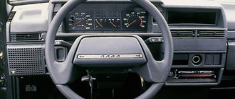
On the VAZ 2107, the steering column switch (also called tube) is a three-lever switch. With its help, the driver controls the turn signals, headlights, windshield wiper and headlight washers.
Reasons for replacing steering column switches may be:
- faulty contacts (turns, headlights do not work);
- mechanical wear of the horn contact;
- control lever failure.
Replacing the steering column switches is carried out as follows:
- Remove the negative terminal from the battery.
- Set the steering wheel to a straight position.
- Remove the decorative trim from the steering wheel.
Inside, we disconnect the eight-, six- and two-pin connectors of the voltage supply harness and remove them from the bottom of the dashboard.
After dismantling the old steering column switch, we install a new one. After putting the steering wheel on, tighten the fastening nut. If all levers and signal are functioning normally, the work can be considered complete.
The torpedo is the most important part of any car. Without indicators showing fuel level, speed, malfunctions in the vehicle, it is impossible to control it properly. If desired, the owner of a VAZ 2107 can replace the dashboard with a more beautiful, comfortable and ergonomic one. In addition, it is useful for every car enthusiast to know how to replace individual dashboard devices if they malfunction.
VAZ instrument panel indicators - explanation
- coolant temperature gauge.
- tachometer;
- left turn signal indicator lamp;
- right turn signal indicator lamp;
- speedometer;
- fuel level indicator;
- fuel reserve warning lamp;
- side light indicator lamp;
- service brake system warning lamp;
- high beam indicator lamp;
- reset button;
- mileage indicator;
- warning lamp for turning on the hazard warning lights;
- "check engine" warning light;
- time and temperature indicator;
- battery charge indicator lamp or battery lamp;
- parking brake warning lamp;
- oil pressure warning lamp;
- reserve.
VAZ dashboard indicators play an important role in informing the user about malfunctions. They help prevent errors in the system, so it is important to know which indicator means what. How does the panel work? If any problem occurs, the sensor immediately sends information to the panel, and the driver will see an orange signal light up.
The earlier version of the instrument panel had some other symbols, such as emergency oil pressure, handbrake engaged, Chek Engine light, and several others that indicate minor operating errors, but which are no longer used.
Broken ground contacts
This problem manifests itself on the panel by displaying incorrect information; the tachometer needle may drop below the current level. The needles of other instruments may also freeze , either permanently or for a short period of time. The panel backlight may also disappear, but the arrows will show the correct data.
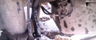
Bolt for fixing ground wires from all devices
Through trial and error, it was found that these glitches can occur due to the fact that the ground contact is broken . Under the dashboard, near the driver’s right foot (near the gas pedal), there is a special mount to which ground wires from all instruments are fixed.
To solve such a malfunction in the operation of the VDO dashboard, you simply need to improve the contact . Unscrew the bolt at “8”, disconnect and clean all contacts suitable for it. To be safe, it is advisable to treat them with “electronic contact cleaner”. After this, all that remains is to connect the wires and screw the bolt back.
When some of the hands work and some don’t work at all, the reason is most likely in their drive motors. Then the panel can only be repaired by replacing the pointer drive motors.
Bottom line of the route display
If you have stopped switching the parameters that are displayed in the bottom line of the route display (under the total or daily mileage), then the problem lies in the steering column switch.
It is responsible for switching between the following options:
- current time;
- outside air temperature;
The buttons on the switch work every once in a while
- travel time (valid from the last reset);
- average fuel consumption;
- instantaneous fuel consumption (changes as the vehicle moves);
- average speed since reset;
- residual power reserve with the remaining fuel in the tank;
- amount of gasoline consumed since reset.
Repair or replacement of the VAZ dashboard
If on a car on the instrument panel none of the indicators installed on it work (speedometer, odometer, tachometer, fuel level and coolant temperature indicators), then the first thing the driver will have to do is check the integrity of fuse F3, which is located in the mounting block . If it has burned out, then before replacing it, you need to find the reason why it burned out, otherwise the newly installed new fuse will have the same fate as the previous one. Most often, fuses burn as a result of a short circuit.
Even if the fuse is intact, then do not be lazy to take it out and check the condition of the contacts. There are cases when the contacts oxidize, and the electrical circuit in this place is interrupted. After making sure that the fuse is intact, the next step is to check the ignition relay, which is located inside the car to the left of the steering column. It is attached to a pin upside down. In the block where this relay is inserted, you can try to short-circuit the power wires using a jumper. If the instrument panel comes to life, the ignition relay will have to be replaced.
If the ignition relay is working properly, there are only two possible reasons for the instrument panel not working: the ignition switch and the mounting block. Before installation on the VAZ-2109 car, the ignition relay and lock contacts often burned out and had to be cleaned by disconnecting the contact group from the lock itself. After changes were made to the principle of supplying voltage to the ignition switch, its contacts began to burn very rarely, but the likelihood of this phenomenon still remained. On the mounting block, in its board, tracks may burn out; in order to see this, the mounting block will have to be removed from the car.
In addition to the reasons listed above, which can lead to failure of the instrument panel, it is also necessary to check the reliability of the fastening of the ground wire. Most common problems:
- burnout of incandescent lamps or failure of the LED group;
- oxidation of connectors;
- electrical wiring fault;
- failure of the fuse box;
- damage to the common contact board;
- no weight on the body (minus) or damage to the dimensions system.
To find a fault, you must use diagnostic equipment, a tester or a voltmeter. If a breakdown is found, you can begin repairs.
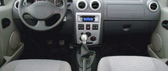
Torpedo VAZ 2107 - its description and purpose
The torpedo (or dashboard) is the front panel of the car, on which the instrument panel, various indicators and indicators, air ducts, etc. are located.
The VAZ 2107 torpedo consists of a large number of different elements:
- Ashtray body.
- Bracket for securing the glove box lid lock.
- Ashtray.
- Glove box lid lock.
- Decorative panel insert for radio receiver mounting.
- Radio receiver mounting panel.
- Insert for the bottom panel of the radio receiver.
- Covering the radio receiver mounting panel.
- Insert for the top panel of the radio receiver.
- Blank for the windshield heating symbol display.
- Dashboard.
- Loudspeaker cover.
- Dashboard.
- Instrument panel insert.
- Glove box body.
- Glove compartment lid.
- Glove box lid hinge link.
- Instrument panel shelf.
Removing the car dashboard
- Using a Phillips screwdriver, remove the three screws that secure the center console;
- remove the cover, the protrusion located at the bottom, remove the protrusion from the bracket;
- Using a nozzle, unscrew the five screws located in the console on the right and remove the screen;
- Disconnect the terminal with the (-) sign from the battery. If there is a radio receiver, you need to remove it, remove the plug from the shield;
- Disconnect the wires coming from the cigarette lighter, remove the cartridge;
- Using a narrow screwdriver, remove the handle from the levers;
- pull the handle towards the heating and fan switch;
- unscrew the two screws above the panel and the two located under it using a screwdriver;
- unscrew the screw located behind the panel;
- Also unscrew the two self-tapping screws securing the cover;
- disconnect the harness and wire connectors. To avoid confusion when installing the panels, you should mark the order in which they are connected;
- unscrew the fastening bolts;
- unscrew the two self-tapping screws, those that secure the bottom bracket using an 8 key;
- unscrew the self-tapping screw securing the light guide and remove it;
- Also unscrew the screws securing the heating unit;
- remove lamp sockets;
- after removing the external parts, remove the decorative insert;
- unscrew all nuts with a 21 key;
- hydrocorrector, remove its lamp;
- Unscrew the screws that are attached to the cross member on the left.
- Finally, the panel itself is removed. The panel is assembled accordingly in the reverse order.
In general, the repair work is quite doable even with your own hands, but before starting dismantling work, you need at least a pinout mapped on paper, otherwise it will be difficult: you will need to “trace” every wire and every connection that is on the “path” from devices to the power button.