Electrical diagram of instruments on the panel
In the VAZ 2109, electrical circuits are placed using a printed circuit board on a board, which is secured by springs with latches on the rear wall of the panel housing. Three groups of plugs can be divided into:
- BSK;
- lighting, dimensions;
- characteristics of the nodes.
The conditional numbering of the nests differs from the standard arrangement. The top plug is numbered 1, then the numbering continues down the right side, and the numbers continue at the top along the left side. BSK terminals have a horizontal position and are numbered from left to right, 2-5 top row, 6-9 bottom.
In instrument circuits with the European version of the torpedo and high, the connector blocks are located horizontally. If you look from the trunk, there are 13 lighting sockets at the top of the BSK, on the right, and operating indicators of the units on the left.
On-board control system
BSK was created on cars with a high modification of the torpedo and the Euro version. Helps monitor the condition of the brake pads and fluid levels in the components while driving. Level sensors are displayed on the panel:
- brake fluid;
- oils;
- coolant;
- washing.
In addition, there is a relay for monitoring the operating condition of the lamps and a sensor indicating the degree of wear of the linings on the brake pads. In normal condition, the indicators do not light up and do not attract attention.
All BSK lights come on when the ignition is turned on for a few seconds and go out. During movement, they begin to glow when the controlled element approaches a critical level, or rather the minimum level for the normal operation of a particular unit. Measures must be taken immediately, since there is no reserve for the signal from the dashboard lamp.
The on-board control system greatly simplifies vehicle maintenance, especially on long routes, and warns of a critical situation. But it does not exclude the need to check oil and brake fluid levels before leaving the garage, regular brake maintenance and changing the linings before they wear out.
Main indicators
The VAZ 2109 has an instrument panel, an electrical circuit on the board, and has different color connectors for the output plugs. Sensors that are most important for safe movement and normal operation of the car are connected to red. These are indicators such as:
- fuel level in the tank;
- parking brake condition;
- carburetor choke position;
- emergency pressure in the system;
- battery charge level;
- fuel injection;
- tachometer.
The right turn indicator lamp and resistors are also connected to this group of connectors. In older models before 1995, VAZ 2109, the electrical circuit does not have BSK connectors, so the distribution of lamps is somewhat different and includes some lamps for emergency and control lights, brake fluid level and hazard warning lights.
Lighting fixtures and dimensions
The white connector of the output plugs is connected mainly to sensors that signal the operation of lighting devices, these are lamps:
- outdoor lighting;
- fog lights;
- dimensions;
- emergency lighting;
- high beam;
- turning indicators;
- stops;
- reverse speed headlights;
- heated rear window.
This group of sockets also includes the connection of such indicators as seat belts not fastened and injection toxicity adjustment, indicators for turning left turns on at the moment of starting to move.
Practical advice
The operation of an injection power unit, and in particular the maintenance of its electronic components, is fundamentally different from carburetor engine systems.
Owners of converted cars must learn a few basic rules:
- Do not start the engine if the terminals of the wires on the battery have poor contact. Be sure to check how tightly they are tightened;
- Do not disconnect the battery while the vehicle engine is running. This is guaranteed to lead to failure of the ECU;
- Monitor the ECU temperature. It is not allowed to overheat (65°C when the car is running and above 80°C, for example when drying in a paint booth). If such a process is unavoidable, remove the ECU from the vehicle for the duration of the work;
- It is also necessary to remove the ECU or disconnect it from the vehicle’s on-board system when carrying out welding work on body parts.
Expert opinion
It-Technology, Electrical power and electronics specialist
Ask questions to the “Specialist for modernization of energy generation systems”
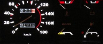
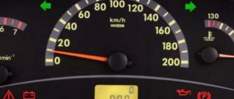
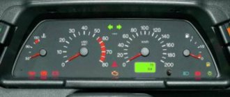
Wiring – VAZ 2109 – injector: features of control sensors and ECU unit Speedometer - shows at what speed the VAZ 2109 is moving, there is also a mechanical dial for daily and total mileage. Ask, I'm in touch!
Travel speed
The speedometer is one of the most important indicators. In addition to the speed of movement, it also shows the distance traveled. On models produced before 1995, this is mainly only the total mileage value. Later models have a daily trip counter and a button that allows you to reset it.
If malfunctions occur in the speedometer, you should check the fastenings and condition of the flexible shaft. Pay attention to bends, the radius of which should be more than 10 mm. Replace the drive cable; if this does not help, then installing a new speedometer is required. The price of services in the salon for this repair is small, so it is better to immediately contact specialists.
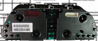
BSK connector
In addition to this connector, 2 tracks from the instrument panel board go to the BSK.
The instrument panel on VAZ 2109 models is equipped with multiple icons and indicators that indicate the status of various car systems. But the owners of “nines” do not always know how all these indicators are deciphered and what functions they perform. In this material we will tell you everything a 2109 car owner needs to know about the dashboard of his car.
Electrical circuit repair
The VAZ 2109 power supply circuit is based on general connection principles. Plus goes from the battery to all devices. The minus for each is indicated separately, from the unit whose operation is signaled by a specific light bulb. Most breakdowns can be fixed with your own hands.
Any video will tell you that if several indicators fail to work, you should start by checking the serviceability of the fuses. Having opened the hood, you will see on the right under it a black box with a diagram of the location of each specific breaker. Select the correct fuse and replace.
Before starting repairs, remember that the instructions for working with electrical circuits, regardless of voltage and current, require turning off the power and discharging the existing capacitors. You shouldn't risk your health. Moreover, you can accidentally short the contacts and completely burn the entire board.
If the control lamps fail, check the fastening in the sockets, clean the contacts and tighten them, which oxidize over time, replace the lamps. Use a tester to make sure there is no broken wire.
Most often, malfunctions occur in the operation of fuel level readings. You should check the setting of the float, which may be knocked down, and the resistor winding responsible for the deflection of the needle. To do this, you need to dismantle the sensor, ring the circuit, making sure it is in good condition and integrity. Then adjust the limiter. All this is done after checking the suitability of the fuses.
If the fuel level indicator arrow constantly changes its position abruptly, the contact between the current collector and the resistor has weakened. In this case, it is best to replace the sensor itself, since correcting this deviation will not be effective.
Panel tuning options
If you decide to tune your instrument panel, then most likely you will be interested in knowing what options exist for doing it. The tuning shield, as you know, pleases the driver’s eye, so this issue is relevant for many car owners.
Dismantling the shield
To tune the dashboard, you first need to remove the device itself.
To do this, you only need to disconnect eight fasteners; to do this, you can use a regular knife:
- First, the fastenings on the driver’s side are disconnected;
- then you need to release the latches located there, on top;
- after this you can disconnect the middle part of the tidy;
- the panel itself is dismantled (the author of the video is Artem Volivach).
Improvement and replacement of backlight
To perform backlight tuning on a VAZ 2109, the lighting sources must be replaced after removal; in this case, it is advisable to use diode bulbs, and if necessary, the scale itself can be modified.
The tuning procedure includes the following steps:
- First, dismantle the standard insert where the scales are located. Remove all the arrows and set them aside, then make corresponding holes for them in the new pads. To prevent the arrows from sticking when operating the instruments, the holes can be made wider.
- Next, you need to remove all the standard lighting sources - just dismantle the entire circuit and install diode devices instead of the old light bulbs. When installing new sources, observe the polarity, since if it is confused, this will lead to the inoperability of the device as a whole.
- Once the lamps are installed, you can begin to refine the scales. Take the new pads and, using fluorescent paint or a marker, paint the numbers on the scales. Such a marker or paint will be required so that when the instrument is illuminated with LEDs, the numbers glow more brightly and stand out.
- After the backlight tuning is completed, you will need to carefully install the circuit and install new overlays on top of it. When installing, be careful not to damage the panel elements.
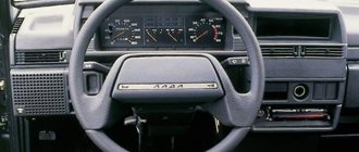
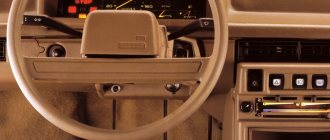
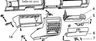
High instrument panel
According to the diagram presented below, the VAZ 2109 with a high panel has the following components.
High dashboard
Item number
What is this
Hazard switch
Windshield wiper and washer control lever
Central nozzles of the interior heating and ventilation system
On-board computer (not available on all trim levels)
Glove compartment lid (glove compartment)
Side nozzles of the interior heating and ventilation system
Speaker (loudspeaker) trim
Power window switches (available on certain trim levels)
Control panel for heating and interior ventilation system
Gearbox shift lever
Hand brake lever
Carburetor choke handle
Horn switch (horn)
Instrument panel light switch
Front seat heating switch (available as standard)
Rear fog light switch
Front fog lamp switch (not available on all trim levels)
Rear defogger switch
Hood lock drive lever
Turn signal and light control lever
Outdoor optics switch
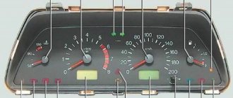
Pinout of the dashboard of VAZ2110, 2111, 2112
- fuel reserve warning lamp;
- dashboard lighting lamps;
- right repeater indicator lamp;
- left repeater indicator lamp;
- VAZ plug block;
- coolant temperature sensor;
- indicator lamp for external lighting;
- carburetor air damper warning lamp;
- oil pressure warning lamp;
- handbrake indicator lamp;
- battery charge indicator lamp;
- VAZ tachometer;
- indicator light “CHECK ENGINE”;
- speedometer dashboard;
- brake fluid level warning lamp;
- hazard warning lamp;
- high beam indicator lamp;
- fuel level indicator.
| White block (X1) | Red block (X2) | ||
| 1 | Housing (weight) | 1 | To terminal “W” of the fuel level indicator sensor |
| 2 | Tachometer (low voltage input from ECU) | 2 | Fuse F19 + 12V power supply |
| 3 | Tachometer (high voltage input from coil) | 3 | Housing (weight) |
| 4 | Const +12V from battery (via 6th fuse) | 4 | Instrument lighting switch |
| 5 | Coolant temperature sensor. | 5 | Turn signal RIGHT |
| 6 | Fuse F1 (side light) | 6 | Turn signal LEFT |
| 7 | Throttle valve (“choke”) | 7 | Brake fluid level |
| 8 | Check Engine Light | 8 | To the trip computer |
| 9 | Fuse F19 + 12V power supply | 9 | Speed sensor |
| 10 | Fuse F19 + 12V power supply | 10 | Terminal “T” fuel gauge |
| 11 | Parking brake, terminal “VK” | 11 | Fuse F3 (high beam) |
| 12 | Generator output “D” | 12 | Hazard switch |
| 13 | Oil pressure sensor | 13 | To terminal “50” of the ignition switch |
Removal
Having familiarized themselves with the diagram of the high instrument panel of the VAZ 2109, many will probably think about the issue of removing it.
There are more than enough reasons to dismantle the panel:
- Repair, modernization of the heating system;
- Body repair;
- Replacing the old panel with a new one;
- Car painting;
- Body sound insulation, etc.
Dismantling process
This is not to say that removing the panel is a difficult process. The main problem is the time that needs to be spent on the work. The task requires concentration and increased attention in order to dismantle all elements, devices, and linings.
The process looks like this.
- Remove the steering wheel itself, otherwise it will seriously interfere with you when dismantling the panel.
- Pull the carburetor choke towards you. Injection engines do not have such an element. Then remove the plastic handle from the drive rod.
- Next, the decorative trim of the console is removed. To do this, simply unscrew the two mounting screws on the sides.
- Dismantle the ashtray and remove the cigarette lighter from its seat.
- Remove the handle that controls the speed of the fan motor.
- Using a screwdriver, pry the levers of the interior heater drive, which will allow you to remove these decorative elements.
- Disconnect the block with wires from the heater fan mode switch.
- Remove the two power wires for the backlight of the stove control panel from the contacts.
- Now you will need to get rid of several decorative control knobs - headlight hydraulic adjustment, instrument lighting control.
- The next step is to dismantle the hydraulic corrector itself and the lighting regulator. You will need a socket wrench that matches the diameter of the mounting nuts you are using. After unscrewing, push them inside. A little later you will be able to take them out.
- The air deflectors for heating the side windows are removed on the left and right.
- Here, using a Phillips screwdriver, you need to unscrew one mounting screw on each side that holds the upper panel covers.
- Remove the exterior light switch from the dashboard. To do this, you need to carefully pry the switch with a flat screwdriver and pull it out. Do not pull too hard as the switch is limited by the length of the wires used. Disconnect the power supply with the wires from the switch and set it aside. The block can still be pushed inside the panel.
- If you have an audio system, remove the radio. Now remove the standard socket from the radio. Of course, if you still have it.
- Unscrew the central fastener from the panel trim.
- Let's start by removing the dashboard trim. Before doing this, be sure to unlatch the latches located under the dashboard. This is done with a pair of flathead screwdrivers. Insert the tools along the edges and press down. By performing upward movements, the panel rises and then is completely removed.
- The cover has been removed, but that's only half the battle. Next, you can easily disconnect the power supply from the cigarette lighter and the cigarette lighter lamp.
- Also, without much difficulty, the wires from the alarm signal and the hazard warning lights are disconnected.
- Be sure to remember to remove the decorative trim from the front speaker and the heated glass switch, plus the rear fog light switch trim. If you also have a speaker, you will need to remove it.
- Reach through the hole under the speaker to disconnect the wiring harness from the fog light and rear window defroster switch.
- The instrument cluster is held on the panel by two mounting screws, which must be unscrewed. Pull it towards you, unscrew the nut and remove the flexible drive cable from the speedometer.
- That's it, the block with wiring from the instrument cluster can be disconnected and put aside for now.
- Do the same with the ignition switch - disconnect the block with wires, remove the ignition relay ground wire from the connector.
- Here, in close proximity, you will see a wire from the air damper warning lamp. But only for the carburetor VAZ 2109. Injection versions are not equipped with this wire.
- On each side of the panel, unscrew one bottom mounting screw.
- Disconnect the power supply wiring for the glove compartment lighting.
- Unscrew the heater panel fasteners and move it down. This way the panel will not disturb you.
- Remove the fasteners for the interior heater guide rod.
- Unscrew all the remaining side top and center fasteners, after which the panel can finally be completely removed.
One of many screws
Your further actions directly depend on the reasons why you decided to go through this difficult path of dismantling the dashboard.
Removing the panel, as you can see, is not a difficult process, but it is troublesome. Lots of parts, elements, fasteners. The most important thing here is to strictly adhere to the instructions and not to forget that dismantling is only half the way. Some people encounter problems during the reassembly process.
How to remove a torpedo on a VAZ 2109 low
- Remove the three heater control knobs.
- Remove the heater fan switch handle by pulling it toward you.
- Remove two screws securing the instrument panel console trim on both sides of the console.
- Slide the cover towards you.
- Disconnect the block with wires from the rear fog lamp switch.
- Disconnect two connectors with wires and one wire from the heated rear window switch.
- Disconnect the block with wires from the hazard warning switch.
- Remove the wiring harness from the exterior light switch.
- Disconnect the connector with the cigarette lighter illumination wires.
- Disconnect the connector with the cigarette lighter wires and remove the console trim.
- Remove the four screws securing the heater control panel.
- Remove the two screws securing the instrument cluster visor.
- Remove the instrument cluster visor.
- Compress the spring clips.
- Remove the instrument cluster housing from the panel.
- Unscrew the fastening nut and disconnect the cable from the speedometer.
- Disconnect the white block with wires from the instrument cluster.
- Remove the hose from the econometric fitting.
- Remove the cotter pin.
- Disconnect the trip odometer reset cable from the speedometer.
- Disconnect the red connector from the instrument cluster.
- Remove the handles for the headlight hydraulic adjustment and the instrument cluster lighting switch by pulling them towards you.
- Unscrew the nut securing the instrument cluster lighting switch.
- Unscrew the nut securing the headlight hydraulic corrector socket.
- Remove the steering wheel and steering column switches.
- Turn the ignition key to position “1” to turn off the anti-theft device, and disconnect the ignition switch wiring harness.
- Remove the two bolts and two nuts securing the steering column pipe.
- Remove the steering column pipe along with the ignition switch.
- Pull the carburetor choke handle towards you until a draft appears, and remove the handle from the rod.
- Remove the two screws securing the air damper guide rod to the instrument panel.
- Remove the screw that secures the instrument panel on the left side.
- Unscrew the screw of the lower fastening of the instrument panel on the left side.
- Remove the screw on the side securing the instrument panel on the right side.
- Unscrew the screw of the lower fastening of the instrument panel on the right side.
- Unscrew the screw securing the instrument panel in the glove box.
- Unscrew one screw securing the instrument panel console on both sides and remove the instrument panel.
Full scheme
1 – block headlight; 2 – gear motor for headlight cleaner*; 3 – engine compartment lamp switch; 4 – sound signal; 5 – electric motor of the engine cooling system fan; 6 – fan motor activation sensor; 7 – generator; 8 – solenoid valve for turning on the headlight washers*; 9 – solenoid valve for turning on the rear window washer* (not installed on the VAZ-21099); 10 – solenoid valve for turning on the windshield washer; 11 – electric motor for glass washer; 12 – oil pressure warning lamp sensor; 13 – carburetor solenoid valve; 14 – carburetor limit switch; 15 – spark plugs; 16 – plug socket for a portable lamp; 17 – engine compartment lamp; 18 – ignition distributor sensor; 19 – carburetor solenoid valve control unit; 20 – windshield wiper gearmotor; 21 – switch; 22 – ignition coil; 23 – starter; 24 – top dead center sensor of the 1st cylinder**; 25 – diagnostic block**; 26 – starter activation relay; 27 – coolant temperature indicator sensor; 28 – reverse light switch; 29 – battery; 30 – brake fluid level sensor; 31 – mounting block; 32 – parking brake warning lamp switch; 33 – brake light switch; 34 – glove box lighting lamp; 35 – heater fan electric motor; 36 – additional resistor of the heater electric motor; 37 – heater fan switch; 38 – backlight lamp for heater levers; 39 – cigarette lighter; 40 – rear window heating switch; 41 – rear fog light switch; 42 – fog light circuit fuse; 43 – alarm switch; 44 – external lighting switch; 45 – ignition relay; 46 – ignition switch; 47 – steering column switch; 48 – instrument lighting switch; 49 – side direction indicator; 50 – lamp switch on the front door pillar; 51 – lamp switch on the rear door pillar (not installed on VAZ-2108 and VAZ-21083); 52 – lampshade; 53 – sockets for connecting individual interior lighting to the lampshade; 54 – switch for the carburetor air damper warning lamp; 55 – turn signal indicator lamp; 56 – indicator lamp for external lighting; 57 – rear fog light indicator lamp; 58 – backup warning lamp; 59 – control lamp for high beam headlights; 60 – indicator lamp for heated rear window; 61 – speedometer; 62 – instrument cluster; 63 – instrument cluster lighting lamps; 64 – coolant temperature indicator; 65 – voltmeter; 66 – fuel level indicator with reserve indicator lamp; 67 – econometrician; 68 – “STOP” indicator lamp; 69 – battery charge indicator lamp; 70 – control lamp for the carburetor air damper; 71 – hazard warning lamp; 72 – brake fluid level warning lamp; 73 – parking brake warning lamp; 74 – oil pressure warning lamp; 75 – rear light; 76 – sensor for level indicator and fuel reserve; 77 – pads for connecting to the rear window heating element; 78 – license plate lights; 79 – rear window wiper gear motor* (not installed on VAZ-21099)
The order of conditional numbering of plugs in blocks:
a – mounting block, instrument cluster, ignition switch and windshield wiper (for blocks with a different number of plugs, the numbering order is similar); b – ignition distributor sensor; c – switch and carburetor solenoid valve control unit; d – headlight units, headlight and rear window cleaners; g – interior lighting lamp; e – fuel level sensor; d – rear lights (pin numbering in order from top to bottom)
* Installed on parts of manufactured cars. ** Not installed since 1995.
Hello everyone, I have already agreed with Ritchi, at the end of the week they will send me a standard shield 2109.
Now let’s remember important things)
Pinout of connectors of the VAZ 2109 instrument cluster with on-board control system
Plug number - Address (purpose) of the plug
1 - Reserve output; 2 - Reserve output; 3 - To the seat belt relay; 4 - Fuse “5” for device protection (“+” for a voltmeter); 5 - To terminal “49aL” of the turn signal and hazard warning relay; 6 — —————–; 7 — —————–; 8 - To fuse “7” for protecting internal and external lighting lamps; 9 - To fuse “14” for high beam protection of the left headlight; 10 - Reserve output; 11 — To the fuel level sensor (output for the fuel level indicator); 12 - To terminal “61” of the generator; 13 - To the temperature indicator sensor.
1- —————– 2 — Fuse “5” for device protection (“+” for powering devices); 3 - To terminal “K” of the ignition coil; 4 - To the instrument lighting switch; 5 - To the fuel injection system control unit; 6 — —————–; 7 - To ground; 8 - To the parking brake switch; 9 - Reserve output; 10 - To the carburetor air damper warning lamp switch; 11 — To the fuel level sensor (output for the fuel reserve warning lamp); 12 - To the oil pressure warning lamp sensor; 13 - To terminal “49aR” of the turn signal and hazard warning relay interrupter.
BSK - 9-terminal connector:
1 — Fuse “5” for device protection (“+” power supply); 2 - To terminal “50” of the ignition switch; 3 - To ground; 4 - To the washer fluid level sensor; 5 - To the oil level sensor; 6 - To the coolant level sensor; 7 - To the brake fluid level sensor; 8 - To brake lining wear sensors; 9 - To terminal “3” of the lamp health monitoring relay.
Instrument panel wires for VAZ 21083, 21093, 21099 cars with a “high dashboard” after 1998. Fuse and relay mounting block 2114-3722010-60.
Diagram of connecting wires to connecting blocks
More articles on electrical VAZ 2108, 2109, 21099
Pinout of the dashboard of VAZ2105, 2106, 2107
Old panel (with oil pressure gauge)
In addition to the presence of an oil pressure indicator, it is worth noting that this instrument panel does not have an air damper indicator lamp (choke), and the emergency oil pressure lamp is located next to the pressure indicator. Because of this, it contains lamps for low brake fluid levels and fog lamps.
White 6-terminal block X1:
- Gasoline level sensor
- Turn signal indicator lamp
- Battery charge sensor (voltmeter -)
- Gasoline level warning lamp
- Overall plus (+)
- Battery charge sensor (voltmeter +)
White 8 terminal block X2:
- Fog lamp warning lamp
- High beam warning lamp
- Dimensions indicator lamp
- Empty
- Battery charge indicator lamp
- Brake fluid level warning lamp
- Empty
- Parking brake warning lamp
Orange 6-terminal block X3:
- General minus (-)
- Tachometer VAZ
- Instrument lighting
- Oil pressure sensor
- Oil pressure warning lamp
- Coolant temperature sensor
VDO instrument panel
Glowing VDO instrument panel from VAZ 2110
I missed the Latvian illuminated instrument cluster (CI) - I didn’t buy it in the summer of 1999, when it cost 600 rubles. And now the situation with them is quite tense, or more precisely, “... there is no delivery and is not expected.” They say that they are in Tolyatti, but for $80 with a speed sensor. Expensive…
However, in markets and stores there is an abundance of VDO instrument clusters for the VAZ 2110 car, model 2110-3801010-02, which is also installed on the 115 VAZ model. In relation to the “eighth” panel, it has disadvantages:
- Doesn’t fit very well; you’ll have to cut the torpedo visor, otherwise some of the lamps will not be completely visible;
- There is no built-in BSK (on-board control system);
- It is necessary to select a fuel level sensor with the appropriate resistance, otherwise the indicator may be “slightly misaligned”.
Otherwise there are only advantages
- All instruments are more accurate, especially noticeable in the fuel level and coolant temperature sensors;
- The speedometer and tachometer are located in the center, all arrows are controlled by stepper motors - the movement of the arrows is smooth;
- The fuel light doesn't blink like crazy, because... it is ignited by electronics, and not by a contact in the tank;
- The total and daily mileage are displayed on the LCD display - when the car is not started, the mileage is not visible on the instrument panel. Relevant for new cars.
- There is a self-diagnosis mode - you need to turn on the ignition while pressing the reset button for the daily mileage counter.
Another plus: the speedometer cable becomes unnecessary, which often makes various sounds - sometimes it clicks, sometimes it clicks... True, I also had to buy a DS (speed sensor, since I have a carburetor car). The sensor needs to be taken only with an iron pin and a connector identical to the connector of the Hall sensor - it is easier and much cheaper to buy a chip for it.
Connection
Three chips fit the standard CP: white (X1) and red (X2), also one smaller red one (for BSK). Before changing the wires, a bundle of wires from the red block was pulled through the window in the dashboard next to the wires of the white block. Otherwise, you won’t be able to remove the dashboard later—tangled wires won’t allow it.
Pinout of the dashboard of VAZ2113, 2114, 2115
There are 26 contacts on the VAZ-2114 instrument panel, each of which is responsible for the operation of the indicators of this panel. If a plus is supplied to the panel, then each contact displays information about the state in which the car is currently located.
White block (X1)
Red block (X2)
- Housing (weight) - black
- To ambient temperature sensor - cyan-magenta
- Tachometer (low voltage input from ECU) - brown/purple
- Fuse F16 (to terminal 15 of the ignition switch) - orange
- Tachometer (high voltage input from coil) - yellow
- Housing (weight) - black
- To fuse F3 of the mounting block (+battery) - white-purple
- Instrument lighting control - white
- Coolant temperature sensor. - green-white
- Turn signal RIGHT - blue
- To fuse F10 of the mounting block - brown
- Turn signal LEFT - blue-black
- Brake fluid level - pink-blue
- Check Engine Light to ECU Controller - White-Purple
- To the trip computer - brown
- To the ECU controller - pink and black
- Speed sensor - gray and yellow
- To the fuel gauge sensor - orange
- To the fuel gauge sensor - pink
- To the parking brake switch - brown-blue
- Fuse F14 of the mounting block - green-black
- Alternator terminal "D" through fuse panel - brown and white
- Hazard switch
- Oil pressure sensor - blue
- To terminal “50” of the ignition switch - purple