Greetings, dear friends, to our website! In today’s article I would like to tell you about such an important part of the car as the starter relay, or, more precisely, about its malfunctions and how to repair it yourself. We will look at the example of a popular domestic car - the Chevrolet Niva.
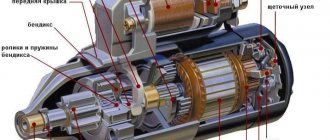
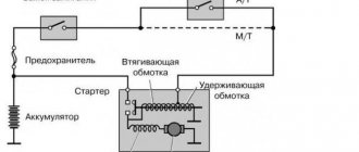
When the engine is started, during the ignition operation, power is supplied to all the windings that are located in the starter. These windings come in two types: retracting and holding. The starter is connected to the retractor winding, and the entire housing control circuit begins to work thanks to the holding winding. When current flows to the terminals, magnetic induction occurs, which creates a magnetic field. Thus, the armature presses on the return spring, and the bendix rotates. When the engine starts running, the power is turned off and the armature returns to its original position as the spring returns it. The contacts are disconnected.
A relay is a device that is constantly powered by electric current from a battery. It consists of a gear with teeth that engages the flywheel ring when the relay begins to operate. As a result, the engine crankshaft rotates and the car starts. During operation, the relay connects the flywheel and bendix gears. The starter will run empty if the relay does not advance the gear.
If the starter relay works well, then the power is at 8 V and the temperature does not exceed 25 ° C. In the case when the power is above this mark, then you need to look for faults in the starter and its relay.
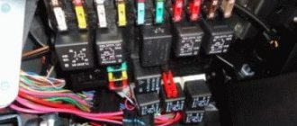
Main block with fuses and relays
This block is located to the left of the steering column and is closed from below with a lid. To get to it, you need to tighten 2 screws, then press the top edge of the cover and gradually free it from all fasteners.
The block that appears will be held on a special bracket. The fuse diagram itself and the number of elements on it may vary depending on the configuration and year of manufacture.
photo of the fuse box in a Chevrolet Niva
For cars manufactured before 2009
Scheme - option 1
Scheme - option 2
Explanation of fuses
F1 (5 A) - license plate lamps, instrument panel lamps, indicator light on the dashboard, engine compartment lamp, additional brake light lamp, left side lamps.
If any of the listed lamps do not work, check this fuse and the lamps themselves, their connectors and wiring.
F3 (10 A) - high beam in the left headlight, indicator lamp for turning on the high beam headlights on the dashboard . Similar to relay K5.
F4 (10 A) - backup fuse.
F5 (30 A) - front door electric windows and their relays . If, when operating the power window, the window goes down but not up (or vice versa), check the button on the door. When lowering and raising, the polarity and direction of rotation of the motor are different. It could also be a problem with the window lift mechanism. To get to it, you need to remove the door trim. Check that the mechanism does not bite anywhere and that the gears are intact, without broken teeth. If there are problems, you can replace the entire power window drive with a new one.
F6 (15 A) - door lock control unit . If one or more doors stop opening, check this fuse. The issue may be in the central locking, control unit, as well as the mechanisms themselves, rods and door locks. If you have no experience, it is better to contact a car service.
F7 (20 A) - sound signal and its relay, cigarette lighter . If the horn does not work, check this fuse, the steering column contacts and the wiring; the contacts may have oxidized and the wiring may have become frayed. Also check the horn itself, you can replace it with another one, for example, a two-tone one from Volga. If the cigarette lighter does not work, check the wiring and its contacts. The white wire is responsible for the backlight, the red and black wires go to the cigarette lighter contacts. Do not insert non-standard connectors into the cigarette lighter, they may cause a short circuit. If the connector in the cigarette lighter moves to the sides, it is better to use a splitter and insert this connector there.
F8 (20 A) - rear window heating element and relay (contacts) . Similar to relay K7.
F9 (20 A) - rear window heating relay coil, additional relay, rear window wiper motor, wiper and washer switch.
F10 (20 A) - backup fuse.
F11 (5 A) - right side lamps.
F12 (7.5 A) - low beam in the right headlight, gear motors for headlight range control . Similar to relay K4.
F13 (10 A) - high beam in the right headlight . Similar to relay K5.
F14 (10 A) - backup fuse. F15 (20 A) - backup fuse.
F16 (10 A) - turn signal and hazard warning light switch (in emergency mode) . Similar to relay K3.
F17 (7.5 A) - interior lighting, individual backlight lamp, brake light lamps, engine control system malfunction warning lamp . If the brake lights do not work, check this fuse, the lamps themselves, their connectors, usually the problem is bad or oxidized contacts. Also check the operation of the brake light switch located near the brake pedal.
F18 (25 A) - heater electric motor and its switch . If the stove blows cold air, the problem may be in the hot air damper, the cable to which comes from the regulator under the casing not far from the gas pedal. The coolant level must be within acceptable limits. If the heater doesn't work or blow at all, it could be the heater motor. Also check the heater switch and its contacts.
F19 (10 A) - turn signal and hazard warning light switch (in turning mode), indicator light in the light switch, turn signal lamps, turn signal indicator lamps on the dashboard, differential indicator lamp . If the turn signals or hazard lights do not work, read the information about relay K3.
F20 (7.5 A) - reserve.
Relay decoding
- Not used
- Windshield wiper motor relay
- Relay-breaker for direction indicators and hazard warning lights
- Low beam relay
- High beam relay
- Auxiliary relay (Tailgate defroster relay coil, heater fan, windshield wiper and washer, tailgate wiper and washer)
- Tailgate glass heated relay
- Reserve
Additional remote relays
They are located slightly below the main block.
- Power window relay;
- Fog lamp relay;
- Relay for horn or heated seats;,
- Exterior mirror drive relay (optional).
For cars manufactured since 2009
Fuse description table
Photo where the Niva Chevrolet starter relay is located
12.5.2 Replacing ball joints
12.5.1. Replacing ball joints
Before proceeding to replacing the ball joint, it must be carefully checked (see subsection 12.5.4).
When carrying out work to replace the hinge, unscrew the drive shaft nut. Since the weight of the car should not rest on a loose wheel bearing, the nut must be unscrewed after installing the car on supports.
The review talks about the Chevrolet Niva starter relay where the photo is located, compiled from the opinion and experience of car owners.
To replace the hinge, perform the following operations:
— loosen the wheel nuts and raise the car slightly;
— loosen the 12-sided nut of the drive shaft and separate the shaft from the wheel hub (see section 8);
This is interesting: How often should you change spark plugs?
— disconnect the bolts securing the drive shaft flange from the gearbox and remove the shaft;
— mark the initial position of the heads of the three indicated in Fig. 262 bolts and remove the bolts;
When installing a new ball joint, do the following:
— insert the ball joint into the steering knuckle;
- Screw on the new nut and tighten it. Along with this, you need to pay attention to the following.
You can find exciting news about the Chevrolet Niva starter relay where the photo is located on our website very soon.
Due to the fact that it is impossible to install a socket with a torque wrench between the ball joint and the steering knuckle, the nut will need to be tightened with a ring wrench to a torque of 35 Nm. The tightening torque will have to be determined approximately. In addition, the ball head bolt can turn at one time.
— remove the wood block and press to set the shock absorber strut to the correct position. At the same time, engage the axle shaft with the wheel hub and at once connect it to the gearbox flange;
- screw in the three shown in Fig. 262 bolts and tighten them by hand. Later move the wishbone until the marked bolt heads are in their previous positions again. Tighten the bolts in this position to a torque of 35 Nm;
— move the drive shaft on the inside to the required position and tighten its bolts to a torque of 45 Nm;
— tighten according to the instructions in section. 8 nut and lower the car to the ground. Tighten the wheel nuts to a torque of 110 Nm.
An exciting and interesting video from YouTube about the Niva Chevrolet starter relay where the photo is located, viewers’ comments and the best moments only with us.
Checking the mechanism: step-by-step instructions
To understand what the fuse means and whether the relay is functioning, it is recommended to pay attention to the following signals:
- a whirring sound coming from under the hood with the engine running but not turning over;
- starter operation without a running engine;
- Starter clicking sounds (won't start).
If such signs are present, the relay should be replaced. Before this, a check is carried out. The device is removed. The contacts on the back wall are closed. To close the circuit, you need to attach a piece of metal or wire. If after this the starter starts working without failures, then the main problem lies in the relay of this element. When the starter starts to operate and the relay starts, then it is the starter that will need to be repaired or replaced.
Guides
- Car manuals, instructions, repair and operation manuals for cars 24 views
- BMW error codes 22 views
- Mercedes error codes 19 views
- Ford car repair and operation manual 15 views
- Fuse and relay box Nissan Primera P12 from 2002 to 2007 14 views
- Repair and operation manual for VW cars 13 views
- Fuse and relay box in Opel Vectra B from 1995 - 2000 12 views
- Honda self-diagnosis 11 views
- Location of diagnostic OBD connector for Citroen 11 views
- BMW car repair and operation manual 11 views
Fuse and relay block Chevrolet Niva from 2002 to 2014
The fuse and relay box is located in the vehicle interior, to the left of the steering column.
Layout of fuses and relays in the Chevrolet Niva block.
Decoding for cars from 2009
Mounting block fuses in the Chevrolet Niva interior
Relay of the mounting block in the car interior
Relays are located at the bottom of the mounting block
- fog lamp relay;
- power window relay;
- seat heating relay;
- horn relay;
- starter relay
Location of relays and fuses in the Chevrolet Niva block
- additional relay (turns on the right electric fan through an additional resistor at low rotation speed);
- fuse (50A) protecting the power circuits of the additional relay and the right electric fan relay;
- fuel pump (fuel pump) fuse (15A), protecting the power circuits of the electric fuel pump relay;
- fuse (15A) protecting the constant power supply circuit of the controller;
- right electric fan relay;
- left electric fan relay;
- electric fuel pump relay;
- main relay;
- fuse (50A) protecting the left electric fan circuit;
- fuse (15A) protecting power circuits switched on by the main relay;
- controller
Principle of operation
The blocking device is responsible for turning on the device strictly at a certain moment. After turning on the ignition, a signal is sent to the starter and the bendix is activated, the armature of the electric motor engages with the flywheel and begins to rotate. An additional relay involves cutting off power to the motor after it has been successfully started.
The starter turns off after the engine starts running, which would be impossible if there was no blocking. The protective insert also prevents overloads and fires in the car.
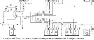
Fuses and relays for Niva Chevrolet
Fuse and relay mounting block Most of the vehicle's electrical power supply circuits are protected by fuses.
The battery charging circuit, engine starting circuit, and generator are not protected by fuses.
Rice. 1
Rice. 1. Mounting block
Rice. 2
Rice. 3. Connection diagram of the mounting block (the outer number in the designation of the wire tip is the block number, and the inner number is the conventional number of the plug)
Rice. 3
Fuses and relays are installed in a block (Fig. 1), which is located in the car interior under the instrument panel on the left side of the steering column. The diagram of the internal connections of the mounting block is shown in Fig. 3.
Protected circuits of the mounting block in the car interior
Designation
Current (A)
Protected elements
License plate lights, side light bulbs in the left headlight and left rear light,
engine compartment lamp, side light indicator lamp
Low beam lamp (left headlight)
High beam lamp (left headlight), high beam indicator lamp
Left fog lamp
Power window relay, front power windows
Horn Relay, Horn, Trunk Lamp
Tailgate heated glass element, Tailgate heated glass relay,
heated exterior mirrors
Heated tailgate glass switch, windshield wiper relay,
windshield wiper motor, windshield washer pump,
right steering column switch, glove compartment lamp, reverse lamps
Remote control unit for electrical accessories (door locking)
Side light lamps in the right headlight and right rear lamp, instrument lighting brightness control
Low beam lamp (right headlight), gear motors for headlight beam control
High beam lamp (right headlight)
Right fog lamp
Outside mirror control unit, electric outside rear view mirrors, heated seat control unit
Relay-breaker for direction indicators and hazard warning lights (in hazard warning mode)
Interior lamps, anti-theft system status warning lamp, brake lights, additional brake light
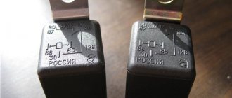
Replacement: step-by-step instructions
Proper replacement of the starter requires a number of measures. There are no difficulties in the work, but you need to follow a certain sequence of actions.
For vehicles on sale before 2009
Replacing the Chevrolet Niva starter relay is performed as follows:
- the terminals from the car battery are disconnected (if this action is neglected, a short circuit may occur, which will also lead to the replacement of the electrical wiring);
- the fuse box located on the left side below the instrument panel opens;
- The starter is being replaced.
To work, you will need a set of tools and hand protection.
For those released after 2009
The main stages of producing a relay replacement will be similar. Pay attention to the fuses, since the circuit is different.
Location and electrical diagram
To protect electrical circuits on cars, fuses are used, located in a special mounting block. On a Chevrolet Niva VAZ 2123, this block is located inside the instrument panel, to the left of the plastic steering column cover. In addition to the main unit, the Chevrolet Niva has an additional unit that is responsible for the operation of the car’s engine. This safety element is located in the passenger compartment and is located on the right side of the instrument panel behind the glove box. The placement of blocks in the cabin is the same for cars of all years of manufacture.
The main blocks of machines are divided into two types - before 2009 and after. These devices are not interchangeable. The blocks behind the glove box are identical in design. On a 2005 car, you can easily install a block from a 2011 car. The designation of the fuse rating is marked on the body; on the assembly itself there is a number of the fuse link and a pictogram of the purpose. There are no fuse markings on the main unit cover.
This is interesting: Why is vehicle diagnostics needed and how often should it be carried out?
For cars manufactured before 2009
2006 Chevy Niva block (diagram inverted)
Explanation of fuses
The block contains fuses for low-load vehicle circuits. For example, it is there that a 25-amp fuse for the heater fan is installed (position F18) and a 20-amp motor insert for driving the wiper blades (number F9).
Assignment of fuses for Niva Chevrolet 2007
Relay description
The main unit contains relays responsible for the operation of the following electrical equipment:
Optional relay for monitoring the integrity of machine lamps. On most machines, jumpers are installed instead from the factory.
Several more relays are installed to the bottom of the main unit.
In cars produced in 2008, this relay is:
- turning on fog lights front and rear;
- starting the window motors;
- activation of a warning signal;
- starting the starter.
Depending on the configuration, there may be more or less.
For cars manufactured since 2009
Block Chevrolet Niva 2010
Description of fuses
The purpose of the fuses on the new units has changed.
Assignment of fuses for Niva Chevrolet 2012
Relay decoding
A part has been added to the additional relay block to turn on the heated seat system.
Engine control system fuse box
The connectors of this KSUD unit can accommodate five relays and five fuses, including a 15-amp protective insert for the fuel pump. The fuel supply pump itself is controlled by a separate relay installed in the same device. The block contains many important elements for protecting the vehicle's electrical circuits. For example, if the fan relay fails, the cooling system will not be able to fully cool the engine.
Power sensor
If various elements in the car do not work, then first of all we begin to look for the fuse that is responsible for this device. This can be easily done if you rely on the information provided above, and take it out of its seat; this can be done with tweezers.
After removal, we carry out a visual inspection of the appearance; if there are no external defects, then we resort to using a tester, switch it to the prozvana mode, and the probes should be placed on the ends of the fuse. If the element is faulty there will be silence, if it is normal, the tester will start making sounds. Once a faulty fuse is found, it should be replaced with a new one designed for the required current value. As you can see, the procedure for detecting and replacing burnt-out elements is not a complicated procedure, and you can do it yourself.
There are two types of car blocks - for those produced before and after 2009. Unfortunately, parts from cars before and after restyling are not interchangeable. But the blocks located behind the glove box have virtually no structural differences. that is why when replacing them, the year of manufacture of the car will not matter.
The protective device may fail due to long periods of use, so if any consumer stops working, the first thing to check is its fuse.
They are held in their nests by sliding contacts. In order to remove the element, simply pull it out of the socket. To make this more convenient, modern mounting blocks are equipped with plastic tweezers.
A faulty fuse can be determined by visual inspection or using an ohmmeter. Since the housings are made of transparent plastic, the integrity of the conductor is easy to determine with the naked eye. In addition, conductor burnout is accompanied by an increase in temperature. Traces of heat exposure remain on the plastic case. Having selected an element suitable for its nominal value, it is inserted into the socket in place of the failed one.
If a fuse burns out on the road, you can replace it with an identical one that protects the circuit of the consumer that is not currently in use.
More information about Chevrolet Niva electronics can be found here.
The ignition relay is located in the passenger compartment fuse box; it can be found on the driver's side of the instrument panel, opposite the seat. On the diagram it is usually designated K6 and in the technical description it is sometimes called an addition relay.
It is responsible for turning on the fuel pump and supplying voltage to other elements. Triggered when the ignition key is turned. At this moment, you can hear a click behind the instrument panel. This electric coil built into the relay receives voltage and closes the contacts of a certain circuit. If there is no characteristic sound when turning the key, this may indicate its failure.
This element is marked K3 in the diagram. It is responsible not only for the turn lamps, but is also activated when the hazard lights are turned on. It has a slightly different structure, unlike K4 and K5, since it has a built-in timer that turns on and off the circuit at a given interval. Thanks to this, it ensures that the lamps flicker.
But if everything is in order with the relay, and the devices do not work, then there may be a problem elsewhere - the mass attachment point. The negative wire coming out of the battery is connected to the car body and goes to some of the main energy consumers in the form of wires. This is sometimes the difficulty when calling an electrician.
The architecture of the circuit can be described as follows: a wiring harness comes out of the negative terminal, connecting devices operating from one ground point, then wires connecting other ground points are connected to them using a crimp sleeve. As a result, finding a specific mass attachment point is quite difficult.
For example, the mass of the mirror control unit is located behind the trunk trim. But with the engine everything is a little simpler. Since it is connected to the frame and body through pads, which are essentially a dielectric, it has its own wiring harness. The terminals are located on the left side of the engine, below the ignition module. They are responsible for the operation of the ECU and ECM sensors.
If, after checking all of the above, you find the reason why the radiator fan does not turn on, you only have to check one wire - the radiator sensor wire. To do this, you must remove the switch as it does not allow access to the fuse box plugs. This means we remove the plug from the fuse block and check the radiator sensor wire for a break.
We check as follows: connect the wire to the “ ” terminal of the battery, install the second end into the connector of the chip. Next, remove the plug from the sensor and connect the light bulb. If there is no light bulb, make a “teal” to ground. If there is no voltage, most likely this wire is broken.
If the fan does not turn on, the reason may be completely unexpected, for example, a burnt gasket under the head. Switching on does not occur for the reason that the coolant does not enter the cylinder, while gases from the cylinder penetrate into the coolant, creating an effect known as an air lock.
WHAT TO DO IF THE RADIATOR COOLING FAN DOES NOT WORK
Problems with the electric motor. If the electric motor fails, its rotor will not spin, and accordingly, the impeller will not rotate. You can check the performance of the electric motor by connecting it directly to the battery. To do this, you will need to take two wires, connect them to two battery terminals and two electric motor terminals.
If the fan does not spin when connected directly to the battery, we can conclude that the electric motor needs to be replaced; Problems with the sensor. If the sensor is unable to detect the coolant temperature and transmit a signal to turn on the electric motor, it will need to be replaced. To make sure that it is not working, you need to disconnect two wires from it and short them together.
If the electric motor starts to spin the impeller, this will indicate that the sensor is faulty and needs to be replaced; There is no tension. The third and most common reason for a non-working radiator cooling fan is the lack of voltage in its power supply circuit. If there is a break in the wires or a fuse fails, the circuit will be de-energized.
RADIATOR COOLING FAN IS NOT WORKING: HOW TO USE THE CAR
Also interesting: Niva generator transfer bracket drawing
Try turning on forced operation of the fan from the battery; If the fan is not forced, you should drive at a constant speed of about 60 kilometers per hour or higher so that the oncoming air flow cools the fluid on the radiator without the help of a fan. It is also recommended to turn on the heating system in the car interior so that some of the heat from the coolant escapes into the cabin.
Technical parameters of Chevrolet Niva (2123) 1.7 / Chevrolet Niva (2123) in a 5-door body. SUV with an 80 hp engine, 5 manual transmission, produced from 2002 to 2009.
The designers of the Chevrolet Niva used a dual fan unit in the cooling system. This slightly complicated the connection diagram, but sharply increased the efficiency of radiator airflow. The fans are driven by 12-volt DC synchronous motors with a permanent magnet inductor. Electric motors have a closed, non-demountable design and do not require maintenance.
The power of each electric motor is 110 W. The fan assembly draws 18 amps.
The fans are turned on one by one using an electromagnetic relay controlled by the on-board computer. When the coolant heats up above 99 degrees, the electric fan located closer to the engine air intake starts. The switch-on temperature of the second impeller is 101 degrees. The fan connection diagram is shown below.
- Voltage is applied to the control terminals.
- Current passes through the inductor, resulting in an electromagnetic field.
- The steel contacts attract and close.
- The current passing through the relay drives the electric motor.
- Disconnect all wires
- Removing the upper pipe
- Removing the bumper
- If there is an air conditioner, bend the tubes (this must be done carefully, as they may burst) or drain the freon (filling it back will not be cheap), then remove the air conditioner radiator.
- You need to loosen the nuts on the radiator casing
- Tilt the radiator so that you can remove the fan unit
- Unscrew the bolts that secure the block and remove it
How to change fuses?
To change the fuse links in the Niva Chevrolet fuse box, you need to understand the electrical circuit of the car. A failed fuse can be identified visually or using a tester. To do this, turn on the device in the closed circuit sound test mode and install the probe tips on the fuse contacts.
Test procedure and tweezers
The replacement itself, for example, a windshield wiper fuse with a rating of 20 A (position F9 on both blocks), is carried out as follows:
- Open the block cover.
- Find the failed insert.
- Take it with tweezers and pull it out of the nest.
- A fuse of the same rating must be installed instead. The use of inserts of a higher rating can lead to burnout of the unit and electrical wiring, as well as to a vehicle fire. Using parts with a lower rating will also not protect the circuit, since such an insert will immediately burn out.
- Turn on the circuit in which the insert was replaced. If re-burnout occurs, then the problem is in the elements of this circuit.
- Place the tweezers in their original place and close the lid.
The process of replacing one of the fuses is shown in the video from the Remgar channel.
Starter and breakdowns
What kind of damage does the starter have? Chevrolet Niva, like any other car, is used quite intensively. This leads to node failure. To begin repairs, you first need to identify the cause of the breakdown. This is the only way to return this important unit to its functionality. If you carry out repair work yourself, you can get by with minimal costs. For example, if the starter on a Chevrolet Niva car does not turn, then often the reason lies not in a breakdown of the unit, but in a discharged battery.
In order for the car engine to start properly again, it is enough to charge the battery. But the battery may be good. Then experts recommend checking the wires - their terminals and contacts may have oxidized.
The process of removing and replacing the block
During operation of the car, the Chevrolet Niva fuse box may become damaged, to correct which it must be removed for repair. If the block cannot be restored, then it should be replaced with a new one. If a part has become unusable on a car, for example, 2004, you can only install an old-style unit on it. When installing a new device, you must ensure that the fuse markings correspond to the electrical diagram.
Preparation
Removing and disassembling the main unit is not a difficult task and will only require two screwdrivers (Phillips and flathead) and 10–15 minutes. The second block will take a little longer to remove.
Stages of work
The sequence of dismantling the unit from a 2007 Niva for maintenance and repair:
- Open the decorative cover of the block.
- Use a Phillips screwdriver to unscrew the self-tapping screw in the upper part, which serves to secure the block in the panel.
- Remove the side clamps of the element from the guides of the metal bracket.
- Disassemble the additional relays with blocks and the main assembly. To do this, carefully pry them up with a flat screwdriver and remove them from the guides.
- Disconnect the electrical wiring connectors from the unit.
- Installation of the part is carried out in the reverse order.
Removing the fuse box for engine management systems
This operation is more labor-intensive, since it requires removing some of the car's interior elements. To do this, you will need a Phillips screwdriver and a 10 mm wrench.
The process of removing the block from a 2013 car:
- Open the glove box lid and unfasten the two safety cords.
- Unscrew the screws securing the glove box lining on the side on the right and two self-tapping screws for fastening it inside the box.
- Unscrew two screws at the bottom (indicated in the photo with blue arrows) and seven more inside the box (red arrows).
- Remove the drawer and disconnect the connector from the backlight.
- In the depths of the instrument panel you will see the control unit and the fuse box, covered with a protective casing. Unscrew the 10 mm nut securing the casing (the type and purpose of the elements are indicated on it).
- Unscrew the three 10 mm nuts securing the fuse box.
- Replace the inserts or the block itself (when replacing fuses, parts of similar ratings should be used).
- Reassemble.
General view of the glove box with the lid open (only the screws indicated by the blue and red arrows should be unscrewed; the screws marked by the yellow arrows should be left in place)
Features of cars with air conditioning
On such Niva Chevrolet, a separate relay and a fuse with a rating of 10 A are used, which protect the power supply to the compressor clutch. The compressor itself ensures the operation of the air cooling system in the cabin.
Replacing such parts on a 2014 car looks like this:
- Using a Phillips screwdriver, unscrew the two screws securing the left console cover.
- Unscrew the 10 mm nut used to secure the relay module and fuse.
- Replace the fuse with a similar one.
- Reassemble the parts in reverse order.