What is it needed for?
Engines do not actually draw fuel from the carburetor. They all have a diffuser, which is a narrowing of the air neck. When air passes through this constriction, a drop in pressure (rarefaction) occurs there. A small hole is installed in this place to supply fuel. Atmospheric pressure, acting on the fuel, squeezes it out of the carburetor's float chamber through this hole into the neck, from where the fuel enters the intake manifold and then into the engine cylinders.
Main details
Float chamber
The float system maintains a constant fuel level in the carburetor float chamber. It works as follows. When the fuel level drops, the float lowers, opens the needle valve and allows fuel to flow into the float chamber. By keeping the fuel level within a certain range, the air/fuel ratio in the mixture is more accurately maintained.
Air damper
The choke system allows you to start a cold engine by enriching the air-fuel mixture. The air damper cuts off the air supply to the carburetor and, accordingly, more fuel enters the engine, and the idle speed decreases. Therefore, a system for increasing idle speed is added to the throttle drive system to increase it when the engine warms up.
Idle system
The idle system provides the fuel required to operate the engine at low speeds when the main metering system is not operating. Adjustment screws allow you to change the air/fuel ratio at idle. Many mechanics believe that this adjustment changes the mixture composition throughout the entire rpm range, but this is not the case.
Acceleration pump
The accelerator pump provides injection of additional fuel when the throttle valve is opened sharply to prevent engine stalling and interruptions in its operation when accelerating the vehicle. If you look inside the carburetor neck and quickly move the throttle linkages, fuel should spray out of the accelerator pump outlets.
Transition system
The transition system provides a transition mode between idle and operation of the main dosing system. Many carburetors have passages or adapter holes near the throttle plates that supply fuel when they open when the throttle valves open.
Main dosing system
It meters the fuel supply to the engine when the car is moving at average speeds. It consists of the main fuel jets, the main distributor and the diffuser. The main fuel jet is located in the channel between the carburetor float chamber and the main sprayer. The main sprayer usually consists of a tube with small air holes. The air here mixes with the fuel to form an atomized fuel-air “fog.” The main fuel jet determines how much fuel will be mixed with a given amount of air.
Mechanics use different sizes of main fuel jets to calibrate the carburetor for different operating modes. By using larger jets the mixture is richer. Conversely, installing smaller jets leans the mixture.
Economizer
The most common are diaphragm type economizers, gauge rods, bypass jets, or economizer valve. When the vacuum in the intake manifold reaches a certain level, the valve opens, allowing additional fuel to flow to the engine.
Economizer valves are selected in accordance with the opening pressure, measured in millimeters of Hg. Art. The economizer valve can be selected according to the operating mode. Engines that typically produce low vacuum should be equipped with economizers that open at low vacuum levels. The metering rods move in and out in calibrated holes according to intake manifold vacuum. When the engine is under load and the vacuum is reduced, the rods extend from the main fuel jets to increase fuel flow.
What carburetor is installed on the ZIL-130 car engine and how is it designed?
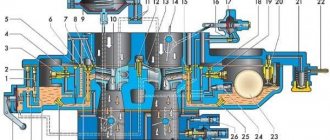
The engine of the ZIL-130 car is equipped with a two-chamber balanced carburetor K-88AE with a falling flow of the combustible mixture. Both chambers operate in parallel in all modes and each feeds four cylinders with a combustible mixture.
The carburetor (Fig. 63) consists of a float chamber 1 with a float 2 and a needle valve 4, resting on the float lever, which is acted upon by a spring 3, trying to hold the needle valve in the closed position, which prevents the float chamber from overflowing when the car is moving on a bumpy road. Fuel is supplied to the float chamber from the fuel pump through the fuel supply fitting 5 through a strainer 6. In addition, in the upper part there is an air pipe 13 with an air damper 15 and an automatic valve 16. The air chamber communicates with the float chamber through channel 14, ensuring balancing. An air filter is installed on pipe 13.
Rice. 63 Carburetor K-88AE
In the middle part of the carburetor there are two mixing chambers 29, each of which contains a small 11 and a large 12 diffuser. An atomizer 10 is installed in the annular slot of the neck of the small diffuser, in which a full power nozzle 8 is installed. Moreover, the throughput of this nozzle is greater than the main fuel nozzle 27. The air into the atomizer passes through the air nozzle 9.
The main fuel jet 27, the full power jet 8, the air jet 9 and the diffusers 11 and 12 form the main metering system of the carburetor.
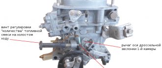
The idle system includes a jet 7, two outlets 33 and 32 and a channel connecting the nozzle to the outlets. The quality of the combustible mixture is adjusted with screws 31.
In the middle part there is an economizer ball valve 19, loaded with a spring 26, which tends to keep it closed. At given moments, the valve pusher is affected by a rod 20, a bar 21 connected to a rod 23, which is connected by an earring to a lever 28, rigidly mounted on the axis of the throttle valves 30. When the economizer valve is open, the fuel enters channel 35 of the full power jet 8. In the middle part also there is a piston 24 with a rod 22 of the accelerator pump, placed in a well, in the lower part of which an inlet ball valve 25 is installed. The well is connected through a channel to the spray nozzle 17. A discharge needle valve 18 is installed in the channel, which prevents fuel from being sucked in when the carburetor is operating at medium loads. Flange 34 attaches the carburetor to the engine intake manifold.
Purpose, main structural elements
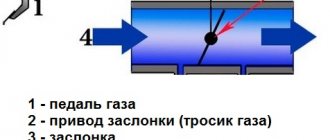
Despite the fact that the entire system “manages” the air supply, it is structurally very simple and its main element is the throttle assembly (many people call it the throttle valve in the old fashioned way). And even this element has a simple design.
The principle of operation of the throttle valve has remained identical since the days of carburetor engines. It blocks the main air channel, due to which the amount of air supplied to the cylinders is regulated. But if this damper was previously part of the carburetor design, then in injection engines it is a completely separate unit.
In addition to the main task - air dosage for the normal functioning of the power unit in any mode, this damper is also responsible for maintaining the required crankshaft speed at idle (idle), and with different loads on the engine. It also participates in the functioning of the brake booster.
The throttle valve design is very simple. Its main structural components are:
- Frame
- Damper with axle
- Drive mechanism
Mechanical throttle assembly
Different types of throttles may also include a number of additional elements - sensors, bypass channels, heating channels, etc. We will consider the design features of throttle valves used on cars in more detail below.
A throttle valve is installed in the air duct between the filter element and the engine manifold. Access to this unit is not difficult in any way, so when carrying out maintenance work or replacement, it is not difficult to get to it and remove it from the car.
Diffuser capacity
The diffuser is one of the main elements of the carburetor.
The defining parameters of a diffuser include its diameter. The choice of diameter strictly depends on the requirements for the engine. The numerical values of the diffuser diameter and other important parameters are initially determined based on engineering practice and experience in designing various motorcycles and engines for them. The final selection of diameter is carried out during testing on the engine. For example, small-capacity two-stroke engines used on mopeds and scooters are equipped with carburetors with a diffuser diameter of 12 to 14 mm. 125 cc sports engines use diffusers with a diameter of 36 to 40 mm. On racing engines with spool valve timing, you can find carburetors with an even larger diffuser. This trend is due to the fact that the diameter of the diffuser determines the maximum throughput of the main air channel, i.e. — maximum filling of the cylinder. The more power it is expected to develop, the larger the diffuser should be, since it will provide less resistance to the flow of the mixture.
However, the large diameter of the diffuser makes the engine less responsive, as it impairs fuel atomization in low and medium load modes. For engines operating over a wide rpm range, throttle response is more important than maximum power. In this case, carburetors with a diffuser of small cross-section are used, which improves the flow of fuel due to greater vacuum.
To increase the throughput without changing the diameter of the diffuser, special inserts are used to eliminate stepwise changes in the cross-section along the air flow path, thereby reducing parasitic turbulence.
Throttle device
The throttle consists of the following elements:
- case - a metal structure that combines all elements of the mechanism;
- the valve itself is a round valve that rotates in one plane on a special axis;
- the axis is a kind of valve, a metal elongated cylinder on which the valve rotates;
- valve sensor - a device that transmits information about the position of the valve to the control unit;
- Idle speed regulator - an additional tube laid to bypass the valve, providing the cylinder group with air during idle.
Setting up the float chamber
This type of work allows you to adjust the optimal amount of gasoline in the float chamber. An incorrect level causes a decrease in power, uneven engine operation, and excessive fuel consumption.
- set of wrenches;
- thin probe (diameter 1 mm);
- pliers.
1. Remove the air filter and unscrew the carburetor cover.
2. Carefully remove the float chamber cover.
3. Check the condition and position of the floats. They should be parallel to the imprints of the side walls of the float bath on the gasket.
4. If they are displaced, we align them by bringing them together or spreading them apart.
5. Next, lay the lid horizontally with the floats up and use a feeler gauge to measure the distance from the bottom of the float to the gasket. It should be equal to 1 mm. If it is higher or lower, we continue further adjustment after installing the carburetor on the engine.
6. When fuel is pumped into the float chamber, its level should coincide with the red lines, as shown in the photo.
7. If the floats are set incorrectly, this level will be lower or higher. Simple adjustment is carried out by bending or bending the tongue of the floats, then closing the carburetor cover and pumping fuel.
For details on setting up the float chamber, see here
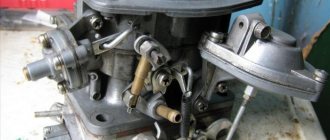
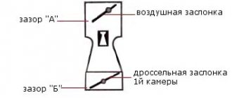
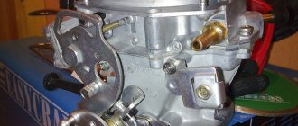
Air damper location
The carburetor consists of an air valve and two small throttle valves. The first is responsible for supplying air to the car engine (indicated by the red arrow in the photo below), and the second is needed to supply additional air-fuel mixture there. They are located at the very bottom of the carburetor; unfortunately, they cannot be seen in the photo. You will find them by shining a flashlight into one of the chambers. These valves also need adjustment; you can learn more about this by reading the article: “Adjusting the throttle valves on a car.”
Adjusting the carburetor with your own hands.
There is nothing scary, much less complicated, about adjusting the carburetor with your own hands. Since all procedures are performed with conventional tools. Unlike the injector, where computer diagnostics are required. So, let's start by adjusting the fuel level.
Adjusting the float mechanism.
The float mechanism is adjusted after washing, before assembly. For this procedure we will need to visually inspect the entire mechanism. Because if the bracket is bent, the system will not work correctly. This will cause the floats to skew and touch the walls of the chamber. But this problem can be corrected manually. We just bend the bracket. And finally, we lower the float to the lower position, thereby opening the fuel valve. Then we measure the distance. There should be 15mm between the float and the valve.
Idle speed adjustment.
Idle speed adjustment is performed with two screws. The screw is “quality”, and the second is “quantity”. First, let's figure out “who is who.” Tighten both screws until they stop. Then back three turns and start the engine. If everything works out, the revs will start to jump. The engine will not run smoothly. If the car does not start, then unscrew both screws one more turn. Then we begin to tighten one of the screws smoothly and slowly. If the engine speed begins to increase, then this is a “quality” propeller. If you tighten the “quantity” screw, the engine will start to stall.
So let's start adjusting. This work is carried out only on a warm engine. We unscrew both screws, find the “quality” from them and begin to tighten them slowly. The engine speed will begin to rise and become more even. At the same time, we also begin to slowly tighten the “quantity” screw, thereby lowering the engine speed. As a result, we need to achieve 800 - 900 rpm and stable operation. And at the end we tighten the “quality” screw a little until the operation becomes unstable. And back one turn. Carburetor adjusted!
Selecting an electric actuator for servicing the air valve and damper
An air ventilation valve is an integral component of the ventilation system, which provides regulation and control of air flows, which allows you to fully serve premises (both office and industrial) with fresh air and significantly increase the level of fire safety.
Externally, the air valve is a device with a metal body. Inside it there is a special blade, which is attached to an axis. The valve is always made individually to the dimensions of the air duct.
The intensity and speed of air flows are adjusted using a manual or automatic electric drive. Thus, choosing a suitable electric drive allows you to solve a number of important problems that are responsible for the efficiency and safety of all ventilation systems.
What should you pay attention to when choosing an electric drive?
In order to select the appropriate actuator for a particular type of valve, the user must consider a number of factors, namely:
- First you need to find out exactly how the actuator is connected to the operating valve? This is done directly or using a lever device. If the actuator is connected directly, then the dimensions of the rod and the original dimensions of the device must be taken into account.
- It is necessary to decide on the type of actuator, what will it be? Manual, electric, pneumatic.
- Functional reference. What functions is the valve purchased for?
How does a carburetor work?
The principle of operation of the carburetor is extremely simple. It pumps air from the atmosphere and, mixing it with gasoline, feeds it into the combustion chamber. From the school course we know that combustion is possible only in the presence of oxygen. A special air filter is used to clean the air entering the combustion chamber. Air injection is ensured throughout engine operation. Gasoline is supplied to the carburetor using a gasoline pump driven by the engine crankshaft or camshaft through a gear system.
The crankshaft speed is controlled using the accelerator drive. It is installed on the carburetor and has a connection to the gas pedal, which goes into the passenger compartment. The actuator opens or closes the valve, which increases or decreases the flow of fuel to the carburetor.
In simple words, a carburetor is a mixer that supplies air mixed with gasoline into the combustion chamber of the engine.
Classification of electric actuators of air valves
Electric drives can be divided into several main types, each of which is focused on performing specific tasks. Thus, manufacturers of electric drives today offer the following types of equipment:
By spring return
- without return spring;
- with return spring.
By management
- Two-position;
- 2- and 3-three-position;
- Modulating.
By torque
- from 2Nm to 40Nm.
By voltage
- 24V;
- 230V.
By auxiliary switches
- without additional switches;
- with additional switches.
Manufacturers focus on two main divisions of electric drives, which in all cases have fundamental differences.
Electronic damper
The last type, electronic, is being introduced into cars more and more. Its main feature is the absence of direct interaction between the accelerator pedal and the damper axis. The control mechanism in this design is already completely electric. It uses the same electric motor with a gearbox connected to the axle and controlled by the ECU. But the control unit “manages” the opening of the damper in all modes. Another sensor was additionally added to the design - the position of the accelerator pedal.
Electronic throttle elements
During operation, the control unit uses information not only from the throttle position sensors and the accelerator pedal. Signals coming from tracking devices of automatic transmissions, braking systems, climate control equipment, and cruise control are also taken into account.
All incoming information from the sensors is processed by the unit and, based on it, the optimal opening angle of the damper is established. That is, the electronic system completely controls the operation of the intake system. This made it possible to eliminate errors in mixture formation. In any mode of operation of the power plant, the exact amount of air will be supplied to the cylinders.
But this system is not without its drawbacks. Moreover, there are slightly more of them than in the other two types. The first of these is that the damper is opened by an electric motor. Any, even minor, malfunctions of the drive components lead to disruption of the unit, which affects the functioning of the engine. There is no such problem with cable control mechanisms.
The second drawback is more significant, but it mostly concerns budget cars. And it comes down to the fact that due to not very well-developed software, the throttle may work late. That is, after pressing the accelerator pedal, the ECU takes some time to collect and process information, after which it sends a signal to the electric motor of the throttle control mechanism.
The main reason for the delay from pressing the electronic gas pedal to the engine response is cheaper electronic components and unoptimized software.
Under normal conditions, this drawback is not particularly noticeable, but under certain conditions such work can lead to unpleasant consequences. For example, when starting to move on a slippery section of the road, sometimes there is a need to quickly change the engine operating mode (“play with the pedal”), that is, in such conditions a quick “response” of the engine to the driver’s actions is needed. The existing delay in throttle response can lead to complications in driving, since the driver does not “feel” the engine.
Another feature of the electronic throttle of some car models, which for many is a disadvantage, is special factory settings for the throttle operation. The ECU contains an installation that eliminates the possibility of wheel slipping at start-up. This is achieved by the fact that when starting to move, the unit does not specifically open the throttle to obtain maximum power; in fact, the ECU “strangles” the engine with the throttle. In some cases, this function has a negative effect.
On premium cars there are no problems with the “response” of the intake system due to normal software development. Also, on such cars it is often possible to set the operating mode of the power plant according to preferences. For example, in the “sport” mode, the operation of the intake system is reconfigured, and in this case the ECU no longer “strangles” the engine at the start, which allows the car to “briskly” start moving.
Spring return actuator
The equipment is designed to work in heating, air conditioning, and ventilation systems. The device primarily performs protective functions. When the air damper of the valve moves to the operating position, a spring is activated in the electric drive, which starts the action mechanism. When the current supply is stopped, the spring still returns the damper to its original position. The basic principle of operation of the return spring is that simultaneously with the rotation of the air damper to its normal position, the spring itself is activated. In the event of a power outage, the damper automatically returns to its initial (protective) position.
Actuator without return spring
This equipment is designed to work correctly with air dampers in air exchange systems. Directly in the drives of this type, the spring, when the power supply is cut off, retains its original position.
The choice of electric drive according to the type of control is of fundamental importance. Speed, convenience and efficiency - all these characteristics are of fundamental importance when it comes to choosing ventilation equipment.
- Two-position control - represents the specificity of control: turning on or off the power supply. Turning on the power supply activates the drive into operating condition. Turning off the power allows the actuator spring to freely return the choke to its standard position.
- Three-point control - with this type of control, the position of the rod does not depend in any way on the specific voltage. The actuator receives an opening or closing signal. The magnitude of the main signal is constant, but it arrives through different channels. When one contact is closed, the actuator assumes an open position (or closed); when the second contact is closed, the actuator operates exactly the opposite. If the power supply is completely absent, the drive stops. Thus, by applying a sequence of electrical pulses to the appropriate contacts, the actuator can be moved to absolutely any position.
- Analog control - with this type of control, the position of the electric drive directly depends on the magnitude of the electrical voltage in the range from 0 to 10V. So, for example, if the controller detects that a valve controlled by an electric drive should be opened halfway, then it sends a signal with a nominal value of 5 Volts. If the valve needs to be fully opened, then the control signal should be 10V. This equipment works exactly on this principle.
Having decided on the type of control, you can proceed to selecting the torque for the electric drive of the air valve. It depends on a number of factors, namely:
- The larger the total area of the air damper, the higher the drive torque must be.
- Swing-leaf valves require less torque than parallel-leaf valves.
- Equipment that is highly sealed requires more torque than dampers without enhanced sealing.
- Ventilation system pressure and specific air flow velocity additionally influence valve torque characteristics.
Important:
The position of the damper and actuator also influences the choice of torque. These factors should also be taken into account. Prefer a valve actuator with a torque rating that is greater than the required damper torque.
Models of carburetors that were installed on the UAZ-452
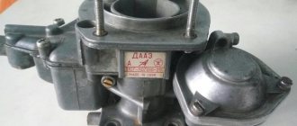
“Loaves” from the first day of their production were equipped with carburetors of the K-126, K-129 types and their modifications. This continued until 1985, when the car was completely modernized. Simultaneously with the new, more powerful engines, the UAZ-452 began to be equipped with K-131 and K-151 carburetors, as well as their numerous improved versions.
But the simplest, most reliable and repairable of them turned out to be the K-126 carburetor, which, among other things, was the most economical. If an engine with K-131 and K-151 consumed an average of 15–17 liters of gasoline per hundred kilometers, then the K-126 allowed saving 3–4 liters. All latest models of UAZ-452 carburetors are interchangeable, except that the K-126 requires an additional gasket between its “fifth” and the intake pipe.
The K-126 line is a generation of carburetors produced (Leningrad), which later became the famous “Pekar”. The first models of two-chamber K-126 were manufactured in 1964 for the new ZMZ-53 engine, which replaced the obsolete GAZ-51.
K-126G carburetors are reliable and economical
Operating principle of the throttle valve
In most models of inexpensive and mid-priced cars, the principle of operation of the mechanism has not changed since the days of carburetor engines.
The air supply to the cylinders is controlled by the driver by pressing the gas pedal. With the help of a drive, the axis on which the damper is located turns it. As a result, the clearance inside the mechanism body (in other words, the opening angle) becomes wider or narrower, and the air supply increases or decreases, respectively.
The level of air supply to the cylinders is recorded by a sensor. It sends the collected information to the electronic control unit of the car. It processes the data and determines how much fuel needs to be supplied to the cylinders.
Mechanical damper, operating principle
This is the simplest and most primitive type, which is still used in some cars.
Mechanical throttle device
The operating principle is as follows:
- The gas pedal is connected to the throttle valve by a cable and swing arms. By pressing the pedal, the driver directly acts on the rotary disk of the damper and it opens to the desired angle;
- The opening angle is recorded by a position sensor, which transmits information to the engine control unit. Accordingly, it is indirectly responsible for the volume of fuel supplied to the injectors.
Throttle position sensors can be of two types:
- Potentiometric (angular displacement sensor). Its design features are a rheostat with a spiral and a sliding contact, which is connected to the throttle valve rotation axis; The device of a potentiometric angular displacement sensor on the throttle valve
- Magnetoresistive . It consists of a slider connected to the damper axis and resistive tracks over which the slider moves. Due to the lack of direct contact between the elements, this sensor is more durable than a potentiometric one.
Diagram of a magnetoresistive angular displacement sensor on the throttle valve
At idle, the throttle is completely closed, so that to operate the engine, air bypasses through the idle speed control - a separate bypass channel where the solenoid valve is located. And for additional air supply (for example, if the driver turns on the air conditioner or other electrical equipment while idling), another channel is provided, which also bypasses the intake manifold.
Modern mechanical sensors are equipped with a heating system for the idle air passages to prevent icing during the cold season. Coolant from the engine is supplied to special pipes, which performs the heating function.
Electromechanical throttle valve
Electromechanical throttle valve device
Its design is almost the same as that of a mechanical one, but with a small addition: it has an electric drive for idling, which is controlled by the ECU. In essence, this drive performs the work of the idle air regulator: it allows air to flow into the engine, even if the driver does not “accelerate”. The remaining elements remained the same: cable connection system, damper position sensor.
Electric (electronic) damper, operating principle
Electronic throttle
Everything here is “grown-up”: no cables or levers, only smart and fast electronics. This system is installed on modern cars, which have the ability to select a driving mode.
Electronic throttle control systems include:
- Gas pedal position sensors. Depending on how hard the driver accelerates, the sensor readings transmitted to the ECU change;
- Throttle position sensor;
- Electric damper drive with gearbox and return mechanism.
Typical operation of an electronic throttle valve
The electronic damper is controlled by the ECU in all modes. In addition, it makes it possible to switch modes: in quiet city driving it will not allow you to pull away too sharply, and in the “drive” mode, on the contrary, it will speed up the engine at the start.
Do-it-yourself carburetor flushing.
Washing with your own hands is quite a jewelry job. Since there are a large number of small parts. Purchase a repair kit first. Since this kit contains all the gaskets, and in some I also saw jets. Regarding the liquid in bolognese, you can also buy it. But I always washed with solvent. Of course, many are against this washing, but I’m not complaining. If you dry it well, there will definitely be no problems.
So, let's get to the point. To wash it, we need to completely disassemble it. That is, unscrew everything that is there. As a result, freeing all the channels for cleaning. We begin to wash away all the dirt and sand, thereby achieving sterility. We also use a tire inflation pump to blow out all the channels. I recommend doing this procedure on a clean and illuminated surface. As a result, after washing, it is necessary to dry the carburetor. Then assemble in reverse order. Carefully placing everything in its place.
Damage to the carburetor air damper
For the carburetor to function properly, the choke valve must operate without any malfunctions. Any jamming of the carburetor air damper leads to increased fuel consumption and difficulty starting a cold engine.
One of the reasons for the damper sticking is the incorrect operation of the return mechanism; in such a situation, it does not return to its position. In addition, the lever or damper axis may be the reason for the choke to not work properly. In this situation, you should check the correct operation of the damper in the engine compartment of the car and eliminate any detected problems.
Another failure of the damper is hidden in the damage to the cable. Often the cable breaks, as a result of which there is no reaction to changing the position of the handle. In this situation, you should replace the damaged cable with a new one. The cable could also stretch, as a result of which the damper will also not respond to the movement of the handle. To solve this problem, unscrew the bolt on the handle that clamps the cable. Then pull the cable to the required length and tighten the fastener. Then check the correct operation of the damper.
When automatically controlling the air damper, the spring most often fails. There is only one solution in this case - replacing the spring. It is also necessary to check the serviceability of the damper axis and control lever.
Carburetor VAZ 2106
The VAZ “six” was produced by the Volzhsky Automobile Plant for 30 years, from 1976 to 2006. The car was equipped with carburetor engines with a volume of 1.3 liters to 1.6 liters. Various carburetors were used as part of the fuel system, but the most common was Ozone.
What is it for?
For any carburetor engine, an integral component is the carburetor, which is designed to prepare the optimal composition of the fuel-air mixture by mixing air and fuel, as well as to supply this mixture to the cylinders of the power unit. For more efficient fuel combustion, mixing with air must occur in certain proportions, usually 14.7:1 (air/gasoline). Depending on the engine operating mode, the ratio may vary.
Economizer
The main metering system of the carburetor is adjusted so that at medium loads the engine runs on an economical mixture. At maximum load conditions, an enriched mixture must be supplied to the engine cylinders. Enrichment of the mixture is provided by an additional carburetor device - an economizer.
The economizer valve 7 is pressed against the seat by a spring 9 and opens under the pressure of a rod 5, which has a piston 3 at the upper end. The piston is placed in a cylinder 4, the lower cavity of which is connected to the air pipe, and the upper cavity is connected to channel 8 with a mixing chamber behind the throttle valve.
The piston with the rod, under the action of spring 2, tends to occupy the lower position. When the throttle valve is opened slightly, a large vacuum is created behind it, which is transmitted through channel 8 to the upper cavity of the economizer cylinder. Under the influence of vacuum, the piston compresses spring 2 and takes the upper position. Valve 7 closes the inlet.
With an increase in the opening of the throttle valve, the vacuum in the air pipe decreases so much that under the action of spring 2, piston 3 will go down, rod 5 will press on valve 7, which will open the inlet hole, and an additional amount of gasoline will begin to flow from the float chamber through nozzle 10 into sprayer 1 - the mixture enriches itself.
Acceleration pump
The accelerator pump is designed to briefly enrich the combustible mixture when the throttle valve is opened sharply.
Rice. Diagram of an economizer with a pneumatic drive: 1 - sprayer; 2 - spring; 3 - piston; 4 - cylinder; 5 - rod; 6 - main jet; 7 — economizer valve; 8 - channel; 9 — valve spring; 10 — economizer jet
In the carburetor body there is a cylinder 8 in which the piston 7 of the pump is placed. The cylinder is connected to the float chamber by a channel, at the beginning of which there is a check valve 9. The outlet channel has a needle valve 10.
The piston is driven by the throttle valve drive mechanism through lever 13, driver 12, rod 11 and pressure plate 4, which acts on the piston through spring 5. When the throttle valve is smoothly opened, the pump piston slowly lowers and gradually squeezes gasoline from the cylinder into the float chamber through the open check valve 9.
When the throttle valve is opened sharply, the piston quickly lowers and squeezes gasoline out of the cylinder. In this case, gasoline lifts the check valve, which closes the inlet, preventing gasoline from escaping back into the float chamber. Gasoline, lifting the needle valve 10, is injected through the nozzle 3 into the carburetor mixing chamber and enriches the combustible mixture.
Carburetor type K-82
Rice. Carburetor type K-82: 1 - flange; 2—emulsion channel; 3 - gasket; 4 — accelerator pump channel; 5 — accelerator pump valve; 6 — accelerator pump nozzle; 7 — small diffuser; 8 - annular slot; 9 — air pipe housing; 10 — air damper; 11 - safety valve; 12 — idle jet; 13 — economizer valve seat with pneumatic drive; 14 — economizer valve needle; 15 - hole through which the float chamber is connected to the air pipe; 16 — screw for adjusting the idle mixture quality; 17 — piston of the pneumatic drive of the economizer; 18 — pressure plate; 19 — economizer valve pusher with mechanical drive; 20 — accelerator pump piston rod; 21 - spring; 22 — filter plug; 23 - mesh filter; 24 - locking needle; 25 - gasket; 26 — float chamber body; 27 — float: 28 — accelerator pump piston; 29 - check valve; 30 — accelerator pump piston drive rod; 31 — rod driver; 32— economizer valve ball; 33 — accelerator pump drive lever; 34 — economizer valve spring; 35 — economizer valve seat; 36 - sealing ring; 37 — economizer piston spring; 38 — main jet; 39 - channel; 40 - plug; 41 — full power jet; 42 — throttle valve; 43 - emulsion tube; 44 — air jet; 45 - outlet
The K-82 type carburetor is a double-diffuser carburetor. It is installed on the engines of ZIL-164A and ZIL-164 cars.
The main metering device, operating on the principle of emulsifying fuel in a sprayer, consists of two fuel jets 38 and 41, an air jet 44 and a sprayer in the form of an annular slot 8 in a small diffuser. An emulsion tube 43 with holes is placed in the well of the main dosing device.
The idle system consists of an idle jet 12, channel 2 and an outlet 45 in the form of a slot. The quality of the combustible mixture at idle is regulated by screw 16, and its quantity by opening the throttle valve.
A piston-type accelerator pump with a mechanical drive from the throttle valve supplies fuel through channel 4 to nozzle 6.
The carburetor has two economizer valves. The mechanically actuated valve consists of a seat 35, a ball 32 and a spring 34, which presses the ball against the seat. A pneumatically actuated valve consists of a seat 13 and a needle 14, which is connected to a piston 17 of the pneumatic actuator. The piston, with the help of spring 37, occupies the upper position when the engine is not running. The space under the piston is connected by channel 39 to the mixing chamber behind the throttle valve.
When the engine is idling, the throttle valve is closed. The vacuum behind the throttle valve spreads through outlet 45 along channel 2 to idle jet 12. As a result, gasoline from the well of the main metering device flows to the idle jet. At the same time, air enters the nozzle. The mixture of gasoline and air, passing through the idle jet, enters the outlet.
Engine operation at medium speed. As the throttle valve opening increases, the air flow passing through the small diffuser increases, as a result of which the vacuum in the diffuser is sufficient for the main metering system to come into operation.
Gasoline from the float chamber flows through jets 38 and 41 into the well. Air also enters here through the nozzle 44 and holes in the emulsion tube 43. The mixture of gasoline and air exits through the annular slot 8 in the small diffuser.
The cross-sections of the fuel and air jets are selected so that a lean mixture is prepared at small and medium throttle openings. In these cases, both economizer valves are closed. The economizer valve with a mechanical drive is closed under the action of spring 34. The valve with a pneumatic drive is closed due to the vacuum in the cylinder under the piston 17. Under the influence of the vacuum transmitted from the mixing chamber, the piston occupies the lower position, compressing the spring 37. Together with the piston, it is in the lower position needle 14, which with its lower end is pressed against seat 13 and closes the fuel channel.
To prevent the vacuum from being transferred to the float chamber, piston 17 in this position sits on the sealing ring 36.
As the throttle valve opening increases, the vacuum under the piston of the pneumatic economizer decreases and the piston rises under the action of spring 37. When the vacuum behind the throttle valve decreases to a certain value (125 mm Hg), the piston and with it the needle 14 will rise so much that the needle opens the inlet hole of the nozzle and an additional amount of gasoline from the float chamber will begin to flow to the full power nozzle 41. The combustible mixture is slightly enriched, which is necessary during unsteady vehicle movement (for example, during acceleration, when the vehicle is moving on dirt roads and terrain).
The mechanically actuated economizer valve opens when the throttle valve is almost fully open.
When the throttle valve is opened, the rod 30 is lowered; when the valve is almost completely open, the plate 18 on the rod 30 presses on the pusher 19, which, when lowered, will open the ball valve. Benzene from the float chamber is additionally supplied to the full power jet 41, the cross-section of which is designed for preparing an enriched mixture.
When the throttle valve is opened sharply, the mixture is enriched by the accelerator pump. In this case, the piston drops sharply and gasoline is squeezed out from under the piston. Check valve 29 is pressed against the seat and closes the channel leading into the float chamber. Gasoline is supplied through channel 4 to jet 6 and flows out of it in a thin stream, enriching the combustible mixture. Enrichment of the combustible mixture when starting a cold engine is carried out by closing the air damper. The air and throttle valves are connected by drive rods so that when the air valve is completely closed, the throttle valve is slightly open. This enriches the mixture sufficiently and ensures reliable engine starting.