Tightening torques for threaded connections VAZ 2106
Home • VAZ • 2106 • Engine
Key points for tightening connections on the VAZ 2106
| Detail | Thread | Tightening torque, N.m (kgf.m) |
| Main bearing cap bolt | M1×1.25 | 68,31–84,38 (6,97–8,61) |
| Oil sump bolt | M6 | 5,10–8,20 (0,50–0,85) |
| Breather cover mounting stud | M8 | 12,7–20,6 (1,3–2,1) |
| Breather cover nut | M8 | 12,7–20,6 (1,3–2,1) |
| Cylinder head bolt: | ||
| M12×1.25 | 33,3–41,16 (3,4–4,2) |
| M12×1.25 | 95,94–118,38 (9,79–12,08) |
| Cylinder head bolt | M8 | 36,67–39,1 (3,13–3,99) |
| Nut securing inlet and outlet pipelines | M8 | 20,87–25,77 (2,13–2,6) |
| Connecting rod cap bolt nut | M9×1 | 43,32–53,51 (4,42–5,4) |
| Flywheel bolt | M10×1.25 | 60,96–87,42 (6,22–8,92) |
| Chain tensioner shoe bolt | M10×1.25 | 41,2–51,0 (4,2–5,2) |
| Camshaft bearing housing stud nut | M8 | 18,33–22,6 (1,87–2,3) |
| Camshaft sprocket bolt | M10×1.25 | 41,2–51,0 (4,2–5,2) |
| Oil pump drive shaft sprocket bolt | M10×1.25 | 41,2–51,0 (4,2–5,2) |
| Valve adjusting bolt nut | M12×1.25 | 43,3–53,5 (4,42–5,46) |
| Valve adjusting bolt bushing | M18×1.5 | 83,3–102,9 (8,5–10,5) |
| Spark plug | M14×1.25 | 30,67–39,0 (3,13–3.99) |
| Coolant pump mounting bolt | M8 | 21,66–26,75 (2,21–2,73) |
| Nut of the stud securing the exhaust pipe of the cooling jacket | M8 | 15,97–22,64 (1,63–2,31) |
| Crankshaft ratchet | M20×1.5 | 101,3–125,6 (10,3–12,8) |
| Generator bracket mounting bolt | M10x1.25 | 44,1–64,7 (4,5–6,6) |
| Generator mounting bracket nut | M10x1.25 | 28,63–45,27 (2,86–4,62) |
| Nut of the bolt securing the generator to the bracket | M12x1.25 | 58,3–72,0(5,95–7,35) |
| Nut securing the mounting plate to the generator | M10×1.25 | 28,08–45,3 (2,86–4,62) |
| Nut securing the cushion to the front support bracket | M10x1.25 | 21,6–35,0 (2,21–3,57) |
| Nut securing the front engine mount to the cross member | M10x1.25 | 27,4–34,0 (2,8–3,46) |
| Nut securing the plate to the pillow | M6 | 5,7–9,2 (0,58–0,94) |
| Nut securing the rear engine mount to the body | M8 | 15,0–18,6 (1,53–1,9) |
| Nut securing the rear support to the gearbox | M8 | 23,3–28,8 (2,38–2,94) |
| Nut of the bolt securing the rear support to the cross member | M8 | 15,9–25,7 (1,62–2,62) |
| Electric fan sensor | M22×1.5 | 40,0–49,4 (4,08–5,04) |
| Clutch bolt | M8 | 19,1–30,9 (1,95–3,15) |
| Clutch and brake pedal mounting bolt nut | M12×1.25 | 12,7–20,6 (1,3–2,1) |
| Clutch and brake master cylinder nuts | M8 | 9,8–15,7 (1,0–1,6) |
| Connection of hydraulic brake pipes | M10 | 14,7–18,6 (1,5–1,9) |
| Connection of hydraulic clutch tubes | M12 | 24,5–31,4 (2,5–3,2) |
| Reversing light switch | M14×1.5 | 28,4–45,1 (2,9–4,6) |
| Bolts securing the clutch housing to the engine | M12×1.25 | 53,9–87,2 (5,5–8,9) |
| Nut securing the clutch housing to the gearbox | M10×1.25 | 31,8–51,4 (3,25–5,25) |
| Nut securing the clutch housing to the gearbox | M8 | 15,7–25,5 (1,6–2,6) |
| Bolt securing the rod clamp cover | M8 | 15,7–25,5 (1,6–2,6) |
| Rear cover fastening nut | M8 | 15,7–25,5 (1,6–2,6) |
| Nut of the rear end of the driven shaft | M20×1 | 66,6–82,3 (6,8–8,4) |
| Intermediate Shaft Bearing Clamp Washer Bolt | M12×1.25 | 79,4–98,0 (8,1–10,0) |
| Bolt securing the fork to the gearshift rod | M6 | 11,7–18,6 (1,2–1,9) |
| Front propeller shaft fork nut | M16×1.5 | 79,4–98,0 (8,1–10,0) |
| Nuts of bolts securing the elastic coupling | M12×1.25 | 57,8–71,5 (55,9–7,3) |
| Nut of the bolt securing the propeller shaft flange to the gearbox flange | M8 | 27,4–34,3 (2,8–3,5) |
| Gearbox mounting bolt | M8 | 35,0–43,2 (3,57–4,41) |
| Differential bearing cover bolt | M10×1.25 | 43,3–53,5 (4,42–5,46) |
| Driven gear bolt | M10×1.25 | 83,3–102,9 (8,5–10,5) |
| Nut for the mounting plate of the axle shaft bearing and brake shield | M10×1.25 | 41,6–51,4 (4,25–5.25) |
| Steering housing mounting bolt nut | M10×1.25 | 33,3–41,2 (3,4–4,2) |
| Nut of a bolt of fastening of a bracket of the pendulum arm | M10×1.25 | 33,3–41,2 (3,4–4,2) |
| Steering linkage ball pin nut | M14×1.5 | 42,1–53,0 (4,3–5,4) |
| Bolt securing the steering shaft to the worm shaft | M8 | 22,5–27,4 (2,3–2,8) |
| Steering wheel nut | M16×1.5 | 31,4–51,0 (3,2–5,2) |
| Nut securing the steering shaft bracket and ignition switch | M8 | 15,0–18,6 (1,53–1,9) |
| Bipod fastening nut | M20×1.5 | 199,9–247,0 (20,4–25,2) |
| Pendulum arm axle nut | M14×1.5 | 63,7–102,9 (6,5–10,5) |
| Bolt securing the cross member to the body side member | M12×1.25 | 78,4–98,0 (8,0–10,0) |
| Nut of the lower bolts securing the cross member to the body side member | M12×1.25 | 66,6–82,3 (6,8–8,4) |
| Nut of the lower arm axle mounting bolt | M12×1.25 | 66,6–82,3 (6,8–8,4) |
| Lower arm axle nut | M14×1.5 | 63,7–102,9 (6,5–10,5) |
| Upper arm axle nut | M14×1.5 | 57,3–92,1 (5,85–9,4) |
| Nut securing the upper end of the shock absorber | M10×1.25 | 27,4–34,0 (2,8–3,46) |
| Nut securing the lower end of the shock absorber | M10×1.25 | 50,0–61,7 (5,1–6,3) |
| Front wheel hub bearing nut | M18×1.5 | |
| Bolt securing the caliper to the bracket | M10×1.25 | 29,1–36,0 (2,97–3,67) |
| Anti-roll bar mounting nut | M8 | 15,0–18,6 (1,53–1,9) |
| Nut securing ball pins to steering knuckle | M14×1.5 | 83,3–102,9 (8,5–10,5) |
| Wheel bolt | M12×1.25 | 58,8–72,0 (6,0–7,35) |
| Steering knuckle bolt nut | M10×1.25 | 50,0–61,7 (5,1–6,3) |
| Shock absorber mounting nuts | M12×1.25 | 38,2–61,7 (3,9–6,3) |
| Nuts of bolts for fastening transverse and longitudinal rods | M12×1.25 | 66.6–82,3 (6,8–8,4) |
New comment
Repair of VAZ 2106 (Zhiguli): Tightening torques for threaded connections
| Thread | Tightening torque, N.m (kgf.m) | |
| ENGINE | ||
| Main bearing cap bolt | M1×1.25 | 68,31–84,38 (6,97–8,61) |
| Oil sump bolt | M6 | 5,10–8,20 (0,50–0,85) |
| Breather cover mounting stud | M8 | 12,7–20,6 (1,3–2,1) |
| Breather cover nut | M8 | 12,7–20,6 (1,3–2,1) |
| Cylinder head bolt: | ||
| M12×1.25 | 33,3–41,16 (3,4–4,2) |
| M12×1.25 | 95,94–118,38 (9,79–12,08) |
| Cylinder head bolt | M8 | 36,67–39,1 (3,13–3,99) |
| Nut securing inlet and outlet pipelines | M8 | 20,87–25,77 (2,13–2,6) |
| Connecting rod cap bolt nut | M9×1 | 43,32–53,51 (4,42–5,4) |
| Flywheel bolt | M10×1.25 | 60,96–87,42 (6,22–8,92) |
| Chain tensioner shoe bolt | M10×1.25 | 41,2–51,0 (4,2–5,2) |
| Camshaft bearing housing stud nut | M8 | 18,33–22,6 (1,87–2,3) |
| Camshaft sprocket bolt | M10×1.25 | 41,2–51,0 (4,2–5,2) |
| Oil pump drive shaft sprocket bolt | M10×1.25 | 41,2–51,0 (4,2–5,2) |
| Valve adjusting bolt nut | M12×1.25 | 43,3–53,5 (4,42–5,46) |
| Valve adjusting bolt bushing | M18×1.5 | 83,3–102,9 (8,5–10,5) |
| Spark plug | M14×1.25 | 30,67–39,0 (3,13–3.99) |
| Coolant pump mounting bolt | M8 | 21,66–26,75 (2,21–2,73) |
| Nut of the stud securing the exhaust pipe of the cooling jacket | M8 | 15,97–22,64 (1,63–2,31) |
| Crankshaft ratchet | M20×1.5 | 101,3–125,6 (10,3–12,8) |
| Generator bracket mounting bolt | M10x1.25 | 44,1–64,7 (4,5–6,6) |
| Generator mounting bracket nut | M10x1.25 | 28,63–45,27 (2,86–4,62) |
| Nut of the bolt securing the generator to the bracket | M12x1.25 | 58,3–72,0(5,95–7,35) |
| Nut securing the mounting plate to the generator | M10×1.25 | 28,08–45,3 (2,86–4,62) |
| Nut securing the cushion to the front support bracket | M10x1.25 | 21,6–35,0 (2,21–3,57) |
| Nut securing the front engine mount to the cross member | M10x1.25 | 27,4–34,0 (2,8–3,46) |
| Nut securing the plate to the pillow | M6 | 5,7–9,2 (0,58–0,94) |
| Nut securing the rear engine mount to the body | M8 | 15,0–18,6 (1,53–1,9) |
| Nut securing the rear support to the gearbox | M8 | 23,3–28,8 (2,38–2,94) |
| Nut of the bolt securing the rear support to the cross member | M8 | 15,9–25,7 (1,62–2,62) |
| Electric fan sensor | M22×1.5 | 40,0–49,4 (4,08–5,04) |
| CLUTCH | ||
| Clutch bolt | M8 | 19,1–30,9 (1,95–3,15) |
| Clutch and brake pedal mounting bolt nut | M12×1.25 | 12,7–20,6 (1,3–2,1) |
| Clutch and brake master cylinder nuts | M8 | 9,8–15,7 (1,0–1,6) |
| Connection of hydraulic brake pipes | M10 | 14,7–18,6 (1,5–1,9) |
| Connection of hydraulic clutch tubes | M12 | 24,5–31,4 (2,5–3,2) |
| TRANSMISSION | ||
| Reversing light switch | M14×1.5 | 28,4–45,1 (2,9–4,6) |
| Bolts securing the clutch housing to the engine | M12×1.25 | 53,9–87,2 (5,5–8,9) |
| Nut securing the clutch housing to the gearbox | M10×1.25 | 31,8–51,4 (3,25–5,25) |
| Nut securing the clutch housing to the gearbox | M8 | 15,7–25,5 (1,6–2,6) |
| Bolt securing the rod clamp cover | M8 | 15,7–25,5 (1,6–2,6) |
| Rear cover fastening nut | M8 | 15,7–25,5 (1,6–2,6) |
| Nut of the rear end of the driven shaft | M20×1 | 66,6–82,3 (6,8–8,4) |
| Intermediate Shaft Bearing Clamp Washer Bolt | M12×1.25 | 79,4–98,0 (8,1–10,0) |
| Bolt securing the fork to the gearshift rod | M6 | 11,7–18,6 (1,2–1,9) |
| CARDAN TRANSMISSION | ||
| Front propeller shaft fork nut | M16×1.5 | 79,4–98,0 (8,1–10,0) |
| Nuts of bolts securing the elastic coupling | M12×1.25 | 57,8–71,5 (55,9–7,3) |
| Nut of the bolt securing the propeller shaft flange to the gearbox flange | M8 | 27,4–34,3 (2,8–3,5) |
| REAR AXLE | ||
| Gearbox mounting bolt | M8 | 35,0–43,2 (3,57–4,41) |
| Differential bearing cover bolt | M10×1.25 | 43,3–53,5 (4,42–5,46) |
| Driven gear bolt | M10×1.25 | 83,3–102,9 (8,5–10,5) |
| Nut securing the flange to the drive gear | see rear axle | |
| Nut for the mounting plate of the axle shaft bearing and brake shield | M10×1.25 | 41,6–51,4 (4,25–5.25) |
| STEERING | ||
| Steering housing mounting bolt nut | M10×1.25 | 33,3–41,2 (3,4–4,2) |
| Nut of a bolt of fastening of a bracket of the pendulum arm | M10×1.25 | 33,3–41,2 (3,4–4,2) |
| Steering linkage ball pin nut | M14×1.5 | 42,1–53,0 (4,3–5,4) |
| Bolt securing the steering shaft to the worm shaft | M8 | 22,5–27,4 (2,3–2,8) |
| Steering wheel nut | M16×1.5 | 31,4–51,0 (3,2–5,2) |
| Nut securing the steering shaft bracket and ignition switch | M8 | 15,0–18,6 (1,53–1,9) |
| Bipod fastening nut | M20×1.5 | 199,9–247,0 (20,4–25,2) |
| Pendulum arm axle nut | M14×1.5 | 63,7–102,9 (6,5–10,5) |
| FRONT SUSPENSION | ||
| Bolt securing the cross member to the body side member | M12×1.25 | 78,4–98,0 (8,0–10,0) |
| Nut of the lower bolts securing the cross member to the body side member | M12×1.25 | 66,6–82,3 (6,8–8,4) |
| Nut of the lower arm axle mounting bolt | M12×1.25 | 66,6–82,3 (6,8–8,4) |
| Lower arm axle nut | M14×1.5 | 63,7–102,9 (6,5–10,5) |
| Upper arm axle nut | M14×1.5 | 57,3–92,1 (5,85–9,4) |
| Nut securing the upper end of the shock absorber | M10×1.25 | 27,4–34,0 (2,8–3,46) |
| Nut securing the lower end of the shock absorber | M10×1.25 | 50,0–61,7 (5,1–6,3) |
| Front wheel hub bearing nut | M18×1.5 | see Front suspension |
| Bolt securing the caliper to the bracket | M10×1.25 | 29,1–36,0 (2,97–3,67) |
| Anti-roll bar mounting nut | M8 | 15,0–18,6 (1,53–1,9) |
| Nut securing ball pins to steering knuckle | M14×1.5 | 83,3–102,9 (8,5–10,5) |
| Wheel bolt | M12×1.25 | 58,8–72,0 (6,0–7,35) |
| Steering knuckle bolt nut | M10×1.25 | 50,0–61,7 (5,1–6,3) |
| REAR SUSPENSION | ||
| Shock absorber mounting nuts | M12×1.25 | 38,2–61,7 (3,9–6,3) |
| Nuts of bolts for fastening transverse and longitudinal rods | M12×1.25 | 66.6–82,3 (6,8–8,4) |
| Detail | Thread | Tightening torque, N.m (kgf.m) |
| ENGINE | ||
| Main bearing cap bolt | M1×1.25 | 68,31–84,38 (6,97–8,61) |
| Oil sump bolt | M6 | 5,10–8,20 (0,50–0,85) |
| Breather cover mounting stud | M8 | 12,7–20,6 (1,3–2,1) |
| Breather cover nut | M8 | 12,7–20,6 (1,3–2,1) |
| Cylinder head bolt: | ||
| M12×1.25 | 33,3–41,16 (3,4–4,2) |
| M12×1.25 | 95,94–118,38 (9,79–12,08) |
| Cylinder head bolt | M8 | 36,67–39,1 (3,13–3,99) |
| Nut securing inlet and outlet pipelines | M8 | 20,87–25,77 (2,13–2,6) |
| Connecting rod cap bolt nut | M9×1 | 43,32–53,51 (4,42–5,4) |
| Flywheel bolt | M10×1.25 | 60,96–87,42 (6,22–8,92) |
| Chain tensioner shoe bolt | M10×1.25 | 41,2–51,0 (4,2–5,2) |
| Camshaft bearing housing stud nut | M8 | 18,33–22,6 (1,87–2,3) |
| Camshaft sprocket bolt | M10×1.25 | 41,2–51,0 (4,2–5,2) |
| Oil pump drive shaft sprocket bolt | M10×1.25 | 41,2–51,0 (4,2–5,2) |
| Valve adjusting bolt nut | M12×1.25 | 43,3–53,5 (4,42–5,46) |
| Valve adjusting bolt bushing | M18×1.5 | 83,3–102,9 (8,5–10,5) |
| Spark plug | M14×1.25 | 30,67–39,0 (3,13–3.99) |
| Coolant pump mounting bolt | M8 | 21,66–26,75 (2,21–2,73) |
| Nut of the stud securing the exhaust pipe of the cooling jacket | M8 | 15,97–22,64 (1,63–2,31) |
| Crankshaft ratchet | M20×1.5 | 101,3–125,6 (10,3–12,8) |
| Generator bracket mounting bolt | M10x1.25 | 44,1–64,7 (4,5–6,6) |
| Generator mounting bracket nut | M10x1.25 | 28,63–45,27 (2,86–4,62) |
| Nut of the bolt securing the generator to the bracket | M12x1.25 | 58,3–72,0(5,95–7,35) |
| Nut securing the mounting plate to the generator | M10×1.25 | 28,08–45,3 (2,86–4,62) |
| Nut securing the cushion to the front support bracket | M10x1.25 | 21,6–35,0 (2,21–3,57) |
| Nut securing the front engine mount to the cross member | M10x1.25 | 27,4–34,0 (2,8–3,46) |
| Nut securing the plate to the pillow | M6 | 5,7–9,2 (0,58–0,94) |
| Nut securing the rear engine mount to the body | M8 | 15,0–18,6 (1,53–1,9) |
| Nut securing the rear support to the gearbox | M8 | 23,3–28,8 (2,38–2,94) |
| Nut of the bolt securing the rear support to the cross member | M8 | 15,9–25,7 (1,62–2,62) |
| Electric fan sensor | M22×1.5 | 40,0–49,4 (4,08–5,04) |
| CLUTCH | ||
| Clutch bolt | M8 | 19,1–30,9 (1,95–3,15) |
| Clutch and brake pedal mounting bolt nut | M12×1.25 | 12,7–20,6 (1,3–2,1) |
| Clutch and brake master cylinder nuts | M8 | 9,8–15,7 (1,0–1,6) |
| Connection of hydraulic brake pipes | M10 | 14,7–18,6 (1,5–1,9) |
| Connection of hydraulic clutch tubes | M12 | 24,5–31,4 (2,5–3,2) |
| TRANSMISSION | ||
| Reversing light switch | M14×1.5 | 28,4–45,1 (2,9–4,6) |
| Bolts securing the clutch housing to the engine | M12×1.25 | 53,9–87,2 (5,5–8,9) |
| Nut securing the clutch housing to the gearbox | M10×1.25 | 31,8–51,4 (3,25–5,25) |
| Nut securing the clutch housing to the gearbox | M8 | 15,7–25,5 (1,6–2,6) |
| Bolt securing the rod clamp cover | M8 | 15,7–25,5 (1,6–2,6) |
| Rear cover fastening nut | M8 | 15,7–25,5 (1,6–2,6) |
| Nut of the rear end of the driven shaft | M20×1 | 66,6–82,3 (6,8–8,4) |
| Intermediate Shaft Bearing Clamp Washer Bolt | M12×1.25 | 79,4–98,0 (8,1–10,0) |
| Bolt securing the fork to the gearshift rod | M6 | 11,7–18,6 (1,2–1,9) |
| CARDAN TRANSMISSION | ||
| Front propeller shaft fork nut | M16×1.5 | 79,4–98,0 (8,1–10,0) |
| Nuts of bolts securing the elastic coupling | M12×1.25 | 57,8–71,5 (55,9–7,3) |
| Nut of the bolt securing the propeller shaft flange to the gearbox flange | M8 | 27,4–34,3 (2,8–3,5) |
| REAR AXLE | ||
| Gearbox mounting bolt | M8 | 35,0–43,2 (3,57–4,41) |
| Differential bearing cover bolt | M10×1.25 | 43,3–53,5 (4,42–5,46) |
| Driven gear bolt | M10×1.25 | 83,3–102,9 (8,5–10,5) |
| Nut securing the flange to the drive gear | see rear axle | |
| Nut for the mounting plate of the axle shaft bearing and brake shield | M10×1.25 | 41,6–51,4 (4,25–5.25) |
| Steering | ||
| Steering housing mounting bolt nut | M10×1.25 | 33,3–41,2 (3,4–4,2) |
| Nut of a bolt of fastening of a bracket of the pendulum arm | M10×1.25 | 33,3–41,2 (3,4–4,2) |
| Steering linkage ball pin nut | M14×1.5 | 42,1–53,0 (4,3–5,4) |
| Bolt securing the steering shaft to the worm shaft | M8 | 22,5–27,4 (2,3–2,8) |
| Steering wheel nut | M16×1.5 | 31,4–51,0 (3,2–5,2) |
| Nut securing the steering shaft bracket and ignition switch | M8 | 15,0–18,6 (1,53–1,9) |
| Bipod fastening nut | M20×1.5 | 199,9–247,0 (20,4–25,2) |
| Pendulum arm axle nut | M14×1.5 | 63,7–102,9 (6,5–10,5) |
| FRONT SUSPENSION | ||
| Bolt securing the cross member to the body side member | M12×1.25 | 78,4–98,0 (8,0–10,0) |
| Nut of the lower bolts securing the cross member to the body side member | M12×1.25 | 66,6–82,3 (6,8–8,4) |
| Nut of the lower arm axle mounting bolt | M12×1.25 | 66,6–82,3 (6,8–8,4) |
| Lower arm axle nut | M14×1.5 | 63,7–102,9 (6,5–10,5) |
| Upper arm axle nut | M14×1.5 | 57,3–92,1 (5,85–9,4) |
| Nut securing the upper end of the shock absorber | M10×1.25 | 27,4–34,0 (2,8–3,46) |
| Nut securing the lower end of the shock absorber | M10×1.25 | 50,0–61,7 (5,1–6,3) |
| Front wheel hub bearing nut | M18×1.5 | see Front suspension |
| Bolt securing the caliper to the bracket | M10×1.25 | 29,1–36,0 (2,97–3,67) |
| Anti-roll bar mounting nut | M8 | 15,0–18,6 (1,53–1,9) |
| Nut securing ball pins to steering knuckle | M14×1.5 | 83,3–102,9 (8,5–10,5) |
| Wheel bolt | M12×1.25 | 58,8–72,0 (6,0–7,35) |
| Steering knuckle bolt nut | M10×1.25 | 50,0–61,7 (5,1–6,3) |
| REAR SUSPENSION | ||
| Shock absorber mounting nuts | M12×1.25 | 38,2–61,7 (3,9–6,3) |
| Nuts of bolts for fastening transverse and longitudinal rods | M12×1.25 | 66.6–82,3 (6,8–8,4) |
1. General information 1.0 General information 1.1 Safety precautions
2. Diagnostics of faults 2.0 Diagnostics of faults 2.1 diagnostics of faults of the engine and its systems 2.2 Diagnostics of faults of the clutch 2.3 diagnostics of faults of the gearbox 2.4 Diagnostics of faults of the cardan drive, rear axle, chassis, steering and braking system 2.5 Diagnosis of faults of the body 2.6. Diagnosis of electrical equipment faults
3. Engine 3.0 Engine 3.1 Cylinder head and timing mechanism 3.2 Lubrication system 3.3 Oil change 3.4 Replacing the camshaft drive chain guide 3.5 Replacing the camshaft and valve levers 3.6 Replacing the valve stem seals 3.7 Replacing the intake and exhaust manifold gaskets 3.8 Replacing cylinder head masonry 3.9 Disassembling the cylinder head, lapping valves
4. Engine power system 4.0 Engine power system 4.1 Replacing the air filter element 4.2 Replacing the fuel pump 4.3 Repairing the fuel pump 4.4 Replacing the fuel tank and its hatch cover
5. Carburetor 5.0 General information about the carburetor 5.1 Cleaning the fuel filter 5.2 Replacing the idle air system solenoid valve 5.3. Adjusting the carburetor 5.4 Replacing the carburetor 5.5. Carburetor repair
6. Engine cooling system 6.0 Engine cooling system 6.1 Replacing the coolant 6.2 Replacing the coolant pump 6.3. Replacing the thermostat 6.4 Replacing the engine radiator
7. Exhaust system 7.0 Exhaust system 7.1 Replacement of exhaust system parts
8. Clutch 8.0 Clutch 8.1 Replacing fluid and bleeding the clutch hydraulic drive 8.2 Adjusting the drive 8.3 Replacing the clutch master cylinder 8.4 Repairing the clutch master cylinder 8.5 Replacing the clutch slave cylinder 8.6 Replacing the pressure plate assembly and clutch release bearing
9. Gearbox 9.0 Gearbox 9.1 Checking the level and changing the oil in the gearbox 9.2 Replacing the reverse light switch 9.3 Replacing the secondary shaft cuff 9.4 Replacing the gearbox 9.5 Repairing the gearbox 9.6 Replacing the speedometer drive 9.7 Features of repairing a five-speed gearbox
10. Cardan transmission 10.0 Cardan transmission 10.1. Maintenance 10.2. Replacing the driveshaft
11. Rear axle 11.0 Rear axle 11.1 Checking the serviceability of the rear axle 11.2 Changing the oil 11.3 Replacing the axle shaft and its cuff 11.4 Removing and installing the rear axle 11.5 Replacing the cuff of the drive gear 11.6 Replacing the gearbox 11.7 Repairing the gearbox
12. Front suspension 12.0 Front suspension 12.1. Maintenance 12.2 Replacing the bearings and hub cuff 12.3 Replacing the cushions and stabilizer bar 12.4 Replacing the ball joints 12.5 Replacing the shock absorbers 12.6 Replacing the springs 12.7 Replacing the upper arms and their rubber-metal hinges 12.8 Replacing the rubber-metal joints of the lower arms on a car 12.9 Replacing the lower arms 12.12 . Adjusting wheel alignment angles
13. Rear suspension 13.0 Rear suspension 13.1 Checking technical condition 13.2. Replacement of rear suspension parts
14. Steering 14.0 Steering 14.1 Adding oil 14.2 Checking the condition of the steering 14.3 Adjusting the gear engagement 14.4 Replacing steering rods 14.5 Replacing and repairing the pendulum arm 14.6 Removing and installing the steering wheel 14.7 Removing and installing the steering shaft 14.8 Removing and installing the steering mechanism 14.9 Removing the bipod
15. Brake system 15.0 Brake system 15.1 Verification of the hydraulic drive 15.2 Checking the vacuum brake amplifier 15.3 Checking the operability of the pressure regulator 15.4 Brake fluid replacement and pumping brake systems 15.5 Front wheel brake pads 15.6 replacement of the rear wheels 15.7 Replacement of the front wheel brake 15.8 Bracket replacement of brakes front wheel cylinders 15.9 Repair of front wheel brake cylinders
16. General information 16.0 General information 16.1. Checking electrical circuits 16.2 Fuse blocks 16.3 Replacing fuses 16.4 Replacing the main and additional fuse blocks 16.5. Replacing the relay 16.6 Replacing the ignition switch 16.7 Replacing the contact part of the ignition switch 16.8 Battery 16.9. Generator 16.10. Starter 11/16. Ignition system 16.12. Lighting, light and sound alarms 16.13. Windshield cleaner and washer 16.14. Repair of the electric heater motor 16.15. Control devices
17. Body 17.0 Body 17.1 Replacing the front bumper 17.2 Replacing the radiator grille 17.3 Replacing the hood latch 17.4 Replacing the hood 17.5 Replacing the windshield 17.6 Replacing the interior rear view mirror 17.7 Replacing the sun visor 17.8 Replacing the ceiling lining 17.9 Replacing the ceiling handrail
18. Heating and ventilation system 18.0 Heating and ventilation system 18.1 Replacing the electric heater fan 18.2 Replacing the heater radiator 18.3 Replacing the radiator casing 18.4 Replacing the heater valve
19. Car body care 19.0 Car body care 19.1 Car washing 19.2 Preservation and protection of paintwork
20. Applications 20.0 Applications 20.1 Tools used in addition to the standard set 20.2 Electrical diagram of VAZ-2106, VAZ-21061, VAZ-21063 cars produced in 1976–1987. 20.4 Tightening torques for threaded connections 20.5 Basic data for adjustments and control 20.6 Characteristics of spark plugs 20.7 Fuel, lubricants and operating fluids used 20.8 Lamps used on the vehicle 20.9 Lip seals (oil seals)
Symptoms of a problem
If you repair the crankshaft yourself, you can save a lot on car service costs. Therefore, it is worth understanding its diagnosis, repair and installation. If repairs are not carried out in a timely manner, the engine may seize, and this can lead to more serious repairs. The following are signs that serve to identify malfunctions:
- when the engine is running, the oil level control light does not go out, which indicates a decrease in oil pressure in the system;
- at medium and high speeds a metallic knock is heard in the engine, which increases with increasing speed;
- engine jams.
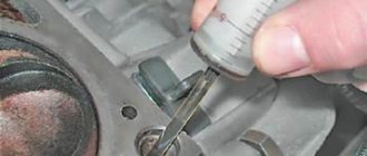
The cause of the first two malfunctions is the wear of the main and connecting rod journals. In this case, the distance between the neck and the liner increases, which leads to a decrease in oil pressure. If the distance is too large, the shaft may run out, causing metallic sounds in the engine. If the engine jams, it is better to replace the crankshaft. To diagnose the serviceability of the crankshaft, it should be dismantled and cleaned. It is better to remove the part together with the engine.
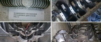
After removal, you need to perform a visual inspection of the necks and cheeks, according to which a decision is made on the need for grinding or replacement. No special instruments are needed for inspection; you can tell by touch. If scratches and burrs are found on the journals, the part is sent for boring. Boring can be done 4 times. Each boring increases the dimensions of the liners by 0.25 mm. After dismantling the crankshaft, you need to evaluate the size of the liners and whether they will allow boring. If grinding has never been performed, then the liners have an icon without any numbers.
If cracks are found, the crankshaft must be replaced. You can send it for welding, but usually restored parts last no more than 50 thousand kilometers. After boring, you need to polish the journals. Then the journals and crankshaft need to be washed with gasoline. The oil passages should also be thoroughly cleaned to prevent contamination from entering the bearings. After washing with gasoline, you need to blow out the oil channels using compressed air.